


Load-adaptive shape sensing and control of a tendon-driven continuum robot actuated by SMA springs
 0
0 Abstract
In this paper, a load-adaptive continuum robot with accurate shape sensing and control capabilities through tendon tension modulation is presented. First, three shape memory alloy (SMA) springs actuate the bioinspired continuum robot to achieve 3D deformation. Second, the bending shape can be accurately estimated in real time using the tensions of the SMA springs based on the forward kinematics of a modified Cosserat model that considers friction between the tendons and disks. For a desired position, the required tensions of the SMA springs can be obtained using the inverse kinematics of the proposed model. Finally, a closed-loop control method is implemented to test the continuum robot’s shape control performance. Experiments demonstrate that the robot exhibits accurate tracking results for different complex trajectories, both with and without an external load at the end effector, based on the proposed model’s forward and inverse kinematics. In conclusion, SMA actuation combined with tension feedback control enables accurate load-bearing capacity, shape sensing, and position tracking, representing a promising approach for developing future design guidelines for continuum robots.
Keywords
INTRODUCTION
Many slender organs and animals, such as a monkey’s tail, snakes, and an elephant’s trunk, as shown in Figure 1A, demonstrate excellent perception and response to complex environmental factors (such as an object’s weight and position), allowing them to carry out sophisticated manipulation tasks[1-4]. Continuum robots, inspired by biological manipulators in nature, are a new type of bionic robot based on a continuous backbone without joints. In contrast to discrete mechanisms with rigid links and joints[5], continuum robots are inherently compliant and flexible due to their ability to elastically deform. However, their low stiffness makes it challenging for such robots to achieve accurate bending shape sensing and control - capabilities that are crucial for practical applications such as navigation or search and rescue operations in complex, congested environments[6-10].
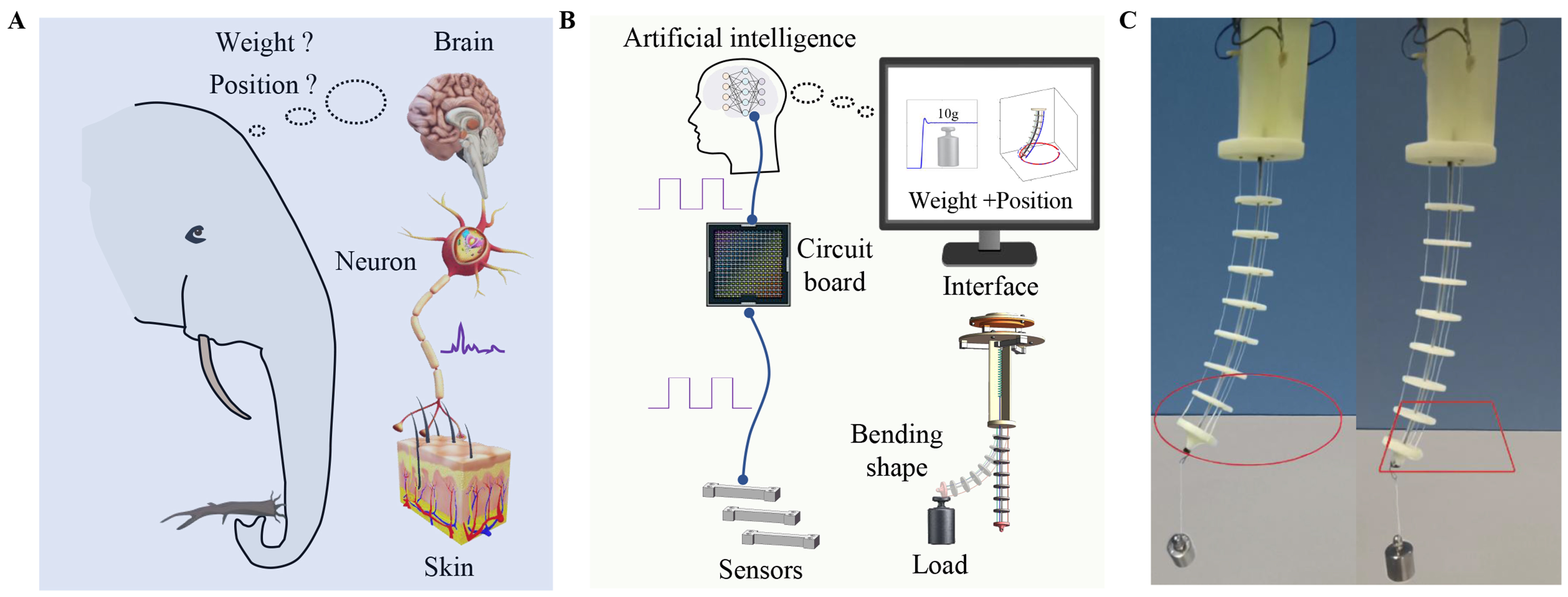
Figure 1. (A) The load and shape perception mechanism of elephants; (B) Load and shape perception mechanism of continuum robots; (C) Experiment on load trajectory control of robots.
Traditionally, embedded strain sensors have been widely used to estimate the shape of continuum robots based on parametric curve assumptions, such as constant curvature (CC) and piecewise constant curvature (PCC), without adequately considering material properties or actuation methods[11-13]. Flexible strain sensors made of elastomeric materials, such as liquid metal[14,15], carbon nanotubes[16,17], and conductive ink embedded in silicone[18,19], can detect CC deformation by converting mechanical stimuli into electrical signals[20]. These sensors offer advantages such as low cost, small size, light weight, high sensitivity, and rapid response speed. Furthermore, they can enable compatible and inherently safe shape sensing when integrated into soft robots. Nevertheless, such flexible strain sensors are typically limited to detecting deformation within a two-dimensional (2D) plane and require a substrate for integration.
Sensing approaches based on vision, electromagnetic fields (EMF), fiber Bragg gratings (FBG), and dual-color layered structure (DCLS) sensors are also used to estimate the three-dimensional (3D) shapes of continuum robots[21]. However, cameras require sufficient space for hardware installation. Embedded cameras increase the weight and volume of the continuum robot, while external cameras cannot obtain shape data when it is obstructed by obstacles[22]. Compared with cameras, electromagnetic sensors have a miniature size, are easier to mount in continuum robots, and can directly provide positional and directional information[23]. However, electromagnetic tracking suffers from inaccuracy due to sparse pose information from distributed sensors, as well as interference from magnetic and metallic conductive objects. FBG sensors offer advantages such as small size, light weight, simple structure, high sensitivity, and fast response speed. They can measure continuum deformation along the length of the robot, are immune to magnetic fields, and thus have excellent anti-electromagnetic interference properties[24,25]. However, FBG sensors are fragile and easily damaged, making them unsuitable for soft structures undergoing large deformations with low stiffness. DCLS sensors can effectively monitor the bending angles and directions of joints of different sizes without requiring additional calibration; however, external environmental temperature significantly impacts their accuracy[26]. Additionally, they require expensive specialized hardware equipment. In summary, shape sensing using strain, vision, EMF, FBG, and DCLS sensors may produce significant errors based on CC and PCC assumptions under external loads or forces.
To achieve accurate shape sensing, methods considering factors such as weight, material, and stiffness have been widely applied in the static and dynamic modeling of continuum robots based on the finite element method (FEM) and Cosserat rod theory, as these approaches accurately represent large deformations[27,28]. FEM has proven effective in simulating continuum robot behavior and is suitable for modeling irregular and nonlinear deformations. However, FEM typically requires substantial computation, making it difficult to meet the efficiency demands of real-time kinematics applications[29]. Methods based on Cosserat rod theory also face limitations: (1) motor-driven actuation systems introduce noise and increase robot weight; and (2) although cameras can provide feedback for position tracking in some robots, shape sensing and control capabilities under unknown payloads remain inadequate. As shown in Figure 1B and C, this paper presents a novel shape memory alloy (SMA)-actuated continuum robot capable of accurate object manipulation in confined spaces. SMA possesses the ability to “remember” and recover its original shape after deformation. Compared to motors and pumps, SMA actuators offer advantages including a high power-to-weight ratio, compact size, and silent operation[30,31] [Supplementary Table 1]. The primary contribution of this work is a continuum robot system capable of autonomous load weight estimation, precise shape sensing, and accurate end-effector tracking, even for objects of unknown weight. This paper is organized as follows: Section “Introduction” describes the continuum robot’s design and fabrication; Section “Experimental” presents the shape sensing method based on forward and inverse kinematics; Section “Results and Discussion” details bending shape sensing and control experiments; Section “Conclusions” concludes the article.
EXPERIMENTAL
Fabrication of the continuum robot
As shown in Figure 2A, the robot is actuated by three SMA springs, enabling bending deformation in 3D space. When no current is applied to the SMA springs, the bent robot returns to its original configuration due to the elastic potential energy stored in superelastic SMA wires. Superelastic SMA exhibits a very high failure strain and large recoverable elastic strain. Three tension sensors measure the tension in the SMA springs, which is used to calculate the bending torque. Many continuum robots face challenges related to low manipulation precision, particularly with unknown payloads. The proposed robot addresses this by measuring object weight, enabling the establishment of an accurate bending model based on Cosserat rod theory.
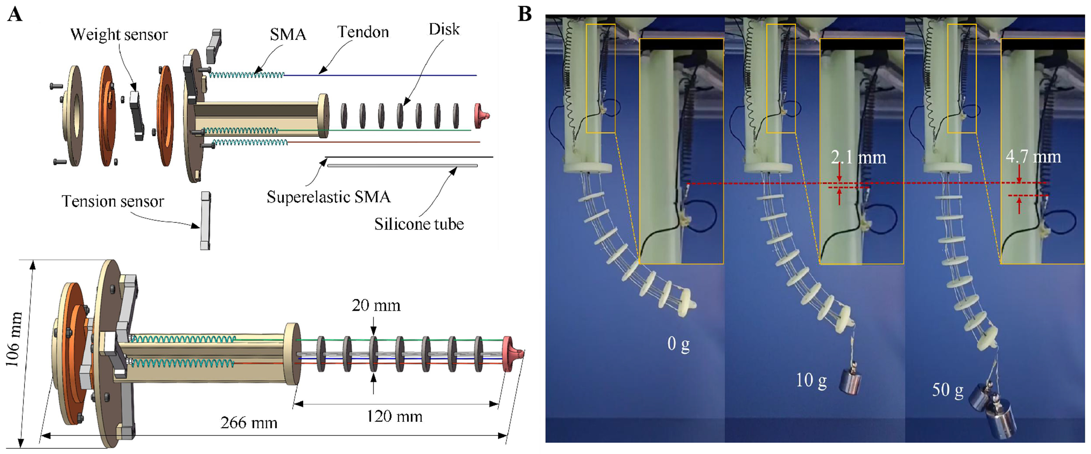
Figure 2. (A) 3D model of the continuum robot; (B) Adaptivity experiment with SMA. 3D: Three-dimensional; SMA: shape memory alloy.
Because the maximum elongation of the SMA springs is 100 mm and the maximum bending angle of the continuum robot is approximately 90°, the dimensions of the robot can be determined accordingly. The prototype robot has dimensions of 266 × 106 × 106 mm (length × width × height), and the detailed information is listed in Table 1.
Mechanical parameters of the robot
| Superelastic SMA | Young’s modulus | 56 GPa |
| Length | 120 mm | |
| Diameter | 0.8 mm | |
| SMA springs | Diameter | 3 mm |
| Length | 15 mm | |
| Maximum output displacement | 85 mm | |
| Maximum output force | 7 N | |
| SMA wire diameter | 0.6 mm | |
| Tension sensor | Rated voltage | 5-10 VDC |
| Range | 0-500 g | |
| Weight | 4.9 g |
The phase transformation of SMA can be stress-induced, enabling the output displacement of SMA actuators to adaptively adjust to the task while maintaining a constant heating voltage[32]. For example, as shown in Figure 2B, the SMA spring extends by approximately 4.7 mm when the suspended weight increases from 0 to 50 g under a constant 5 V heating voltage. Unlike actuators such as motors, which maintain a fixed tendon length under constant input, SMA springs offer greater flexibility to prevent robot damage. In summary, the prototype robot demonstrates excellent adaptability to unstructured environments and complex tasks.
Shape sensing based on tension and Cosserat rod theory
Cosserat rod theory
The CC model, due to the approximation of circular curves, cannot accurately be used to derive a robot model with the assumption of no gravity or no external loads. Here, we use Cosserat rod theory to model the bending shape of a soft finger, which is affected by its body weight[33,34]. Figure 3A shows a Frenet–Serret coordinate frame of a soft finger, which is a one-dimensional rod. In this figure, O–XYZ is a global frame, which is stationary with respect to the base; o–xyz is a local frame located at any point in the rod. Each point of the rod can be parameterized by its unstretched length, here represented by the variable s. The position of any point s in the global frame can be expressed as p(s), while the infinitesimal element in the local frame can be expressed as pl(s). In accordance with Cosserat rod theory, a rod can be parameterized by its centerline curve in space with a three-element vector p(s) ∈ R3 to represent the location of a point on the rod and a matrix R(s) ∈ SO(3) to specify the orientation of a local frame with respect to the global coordinate frame.
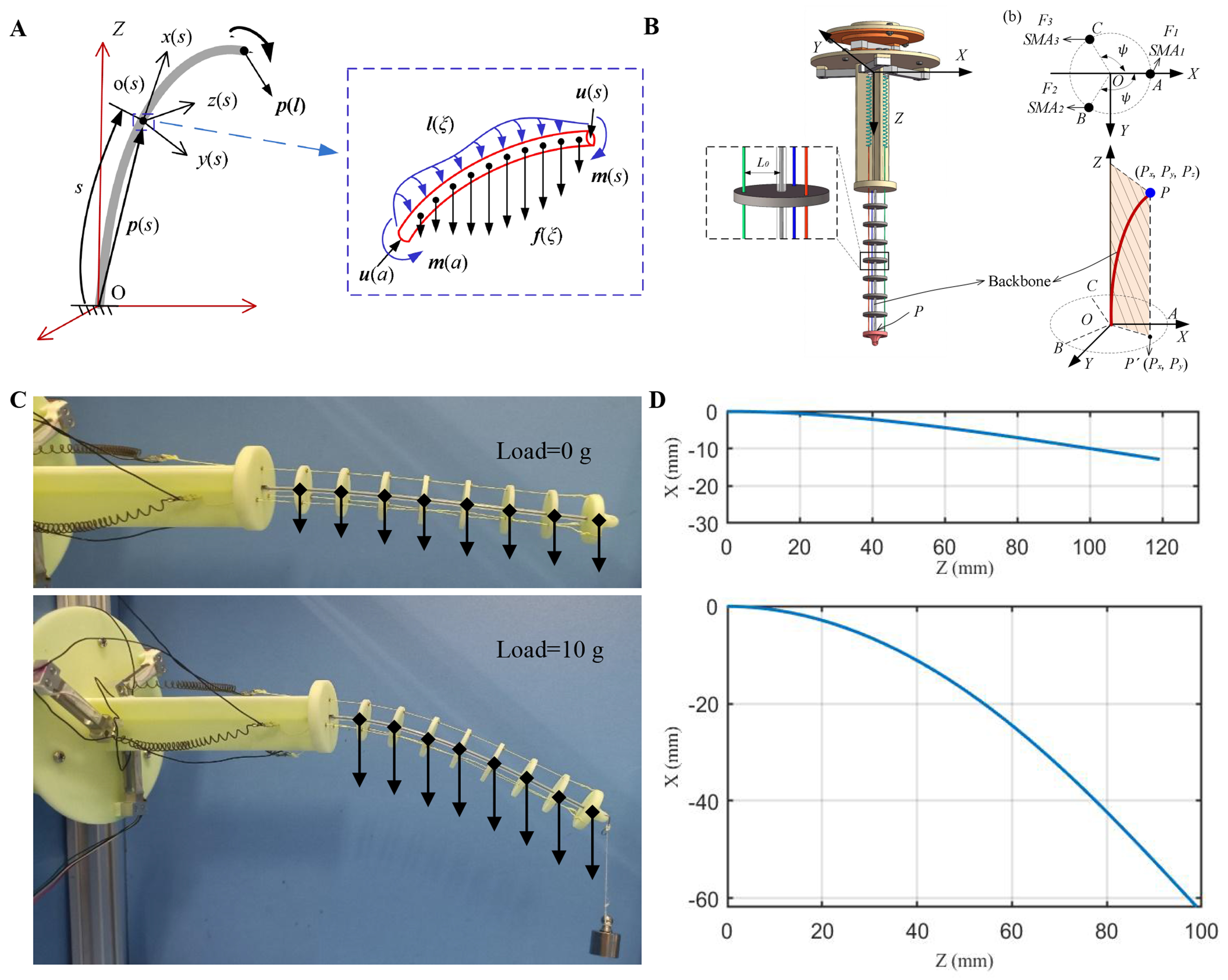
Figure 3. (A) Theoretical scheme based on the Cosserat model; (B) SMA actuation method based on inverse kinematics; (C) Continuous Robot Parameter Recognition Experiment; (D) Simulation of Continuous Robot Parameter Recognition. SMA: Shape memory alloy.
The variables vl(s) represent the linear rates of change of the rod’s position with respect to s in the local frame, defined by vl(s) = dpl/ds, in the global frame,
where the dot · denotes a derivative with respect to s. In a similar manner, the angular rates of change in the rod’s orientation with respect to s in the global frame are given by
where ^ indicates the conversion of the angular variables ul(s) into a skew-symmetric matrix.
The distributed external forces and moments applied to the arbitrary section of the rod are specified by f and l, respectively, and the internal or point forces and the moments in the global frame coordinates are denoted by n and m, respectively. In addition, ξ is the position variable in the local frame ranging from position s to a. Therefore, the force and torque equations of static equilibrium can be expressed as
The initial linear and angular variables in the local frame are specified by v*(s) and u*(s) for the undeformed reference configuration, and the constitutive equations are thus written as
where Er is the modulus of elasticity, G is the shear modulus, Ir(Irx, Iry) is the second moment of area, J is the polar moment of inertia, and Ar is the cross-sectional area of the rod.
In this study, the stretch and compression of the continuum robot is neglected. The distributed force acting on the robot is its weight, which is expressed as f(ξ) = ρAgeg, where ρ and A are the equivalent density and cross-sectional area of the robot, respectively, and g is the gravitational acceleration, defined herein as eg = [0, 0, 1]T. The boundary conditions for a rod that is clamped at s = 0 and subjected to an applied force T and moment M at s = l are R(0) = R0, p(0) = p0, m(l) = T, and n(l) = M.
Forward kinematics
As shown in Figure 3A, for the forward kinematics, the unknown parameters are the position p(l) and pose R(l) at end point, which can be calculated according to the shooting method using MATLAB’s “fsolve” solver[28]. Specifically, the input values are the position R(0) and rotation matrix p(0) at s = 0 and the applied force T and moment M at s = l. p(l) and R(l) at s = l can be solved iteratively by guessing the unknown initial applied force T0guss and moment M0guss. The estimated p(l) and R(l) can be obtained if the error Δe < ε. The fourth-/fifth-order Dormand–Prince adaptive step size solver implemented in MATLAB’s “ode45’’ routine is used to achieve highly accurate steady-state solutions. The pseudocode of forward kinematics computation is given in Algorithm 1.
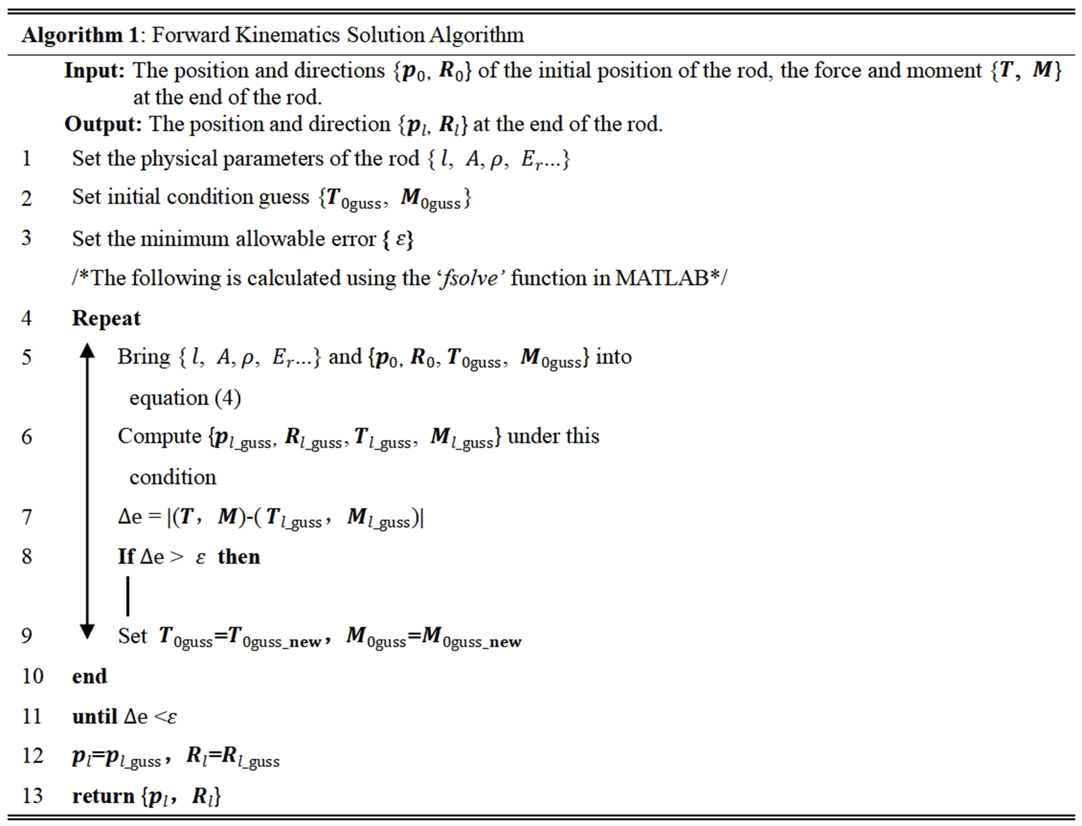
Algorithm 1.
Inverse kinematics
Forward kinematics are used to estimate the bending shape of the continuum robot based on the measured force T and moment M. To achieve control of a continuum robot, a fast and reliable inverse kinematics solution is a critical factor for position tracking. Unlike forward kinematics, the input values in inverse kinematics are the position p(0) and rotation matrix R(0) at s = 0 and the applied force T and position p(l) at s = l, while the moment M at the end of the rod can be solved by the shooting method. The pseudocode of inverse kinematics computation is given in Algorithm 2.
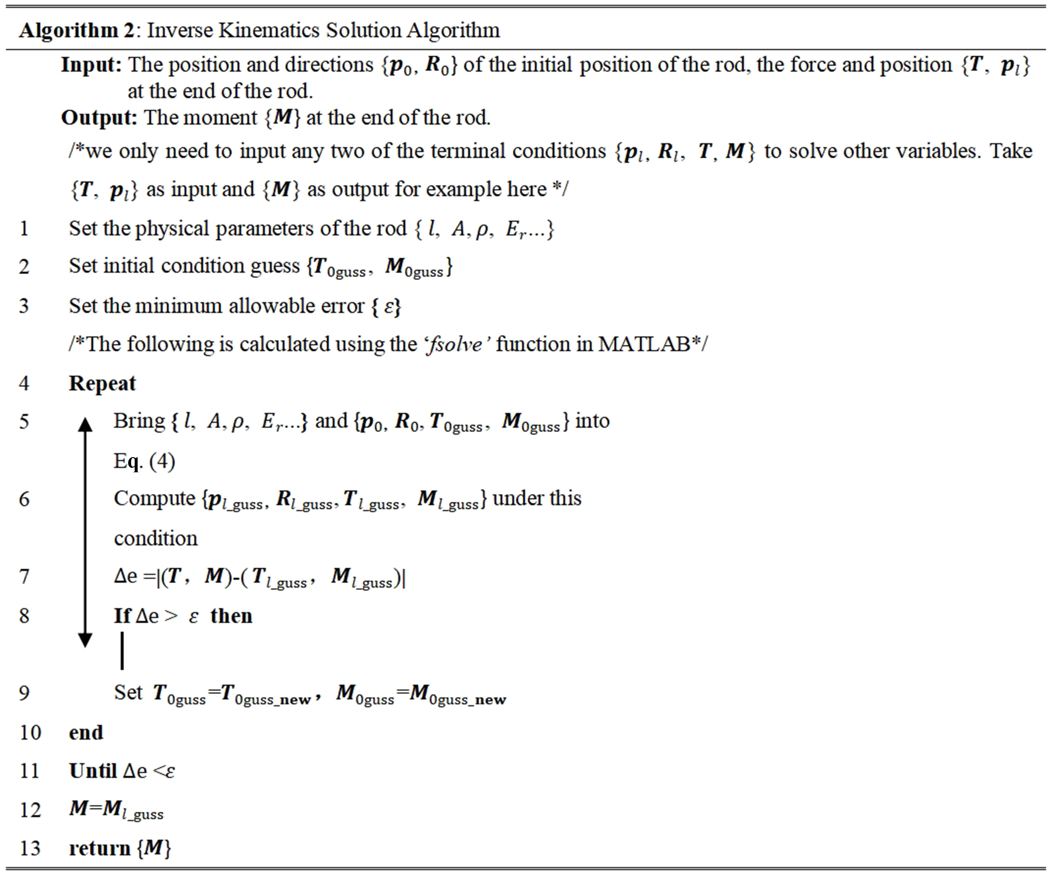
Algorithm 2.
As shown in Figure 3B, the moment M can be expressed as
where F1, F2, and F3 are the output forces of the SMA springs and L0 is the lever arm. Mx and My are the moments along the X and Y directions, respectively. Although three SMA springs can be actuated at the same time, for a given point P in the workspace of a continuum robot, only one or two SMA springs need to be actuated. Then, Equation (7) can be simplified by using the projected position of point P on the XOY plane when the projected area is divided into three sections by boundary lines OA, OB and OC. For example, SMA1 and SMA3 need to be actuated when the position of point P′ (the planar projected point of P) is in the area
Parameter identification
To test the accuracy of the forward kinematics model, several parameters need to be identified. First, the distributed force of the robot needs to be calculated. The equivalent density can be expressed as
where md and mb are the masses of the disks and backbone, respectively, and vr is the volume of the backbone. The cross-sectional area can be defined as A = πr2, where r is the radius of the backbone. Detailed information is listed in Table 2.
Parameters for simulation and experiments
| Parameter | Value | Parameter | Value |
| md | 5.04 g | mb | 0.6 g |
| l | 120 mm | r | 0.4 mm |
| vr | 6.03 × 10⁻⁸ m3 | A | 5.03 × 10⁻⁷ m2 |
| ρ | 9.35 × 10⁴ kg/m3 | Er | 77.59 GPa |
| L0 | 8 mm | ψ | 120° |
As shown in Figure 3C and D, the continuum robot without tendon tension is positioned horizontally, which demonstrates a bent shape due to the weight of the robot and external load. The average error ΔE of point P (PX, PY, PZ) between the simulation and experimental result is expressed as
where (Px, Py, Pz) is the simulated result of the tip position; Δex, Δey and Δez are the absolute errors between the simulation and experiment on the X, Y and Z axes, respectively. The simulation accurately predicts the deflection with a variety of known external loading conditions at the tip. The average error ΔE increases from 0.92 to 1.42 mm as the load increases from 0 to 30 g. Detailed information is listed in Table 3.
Tip error between simulation and experiment
| Load | Real | Simulated | (Δex, Δey, Δez) | ΔE |
| 0 g | (-12, 0, 119) | (-12.9, 0, 119.2) | (0.9, 0, 0.2) | 0.92 |
| 10 g | (-42, 0, 111) | (-42.9, 0, 110.4) | (0.9, 0, 0.6) | 1.08 |
| 20 g | (-62, 0, 100) | (-61.8, 0, 98.9) | (0.2, 0, 1.1) | 1.12 |
| 30 g | (-74, 0, 91) | (-73.1, 0, 88.9) | (0.9, 0, 1.1) | 1.42 |
The SMA springs contract and expand the tendons to bend the continuum robot. However, the actual bending moment applied to the continuum robot is less than the moment calculated using Equation (7) due to the friction between the tendons and disks. As shown in Figure 4A, the modified force can be expressed as
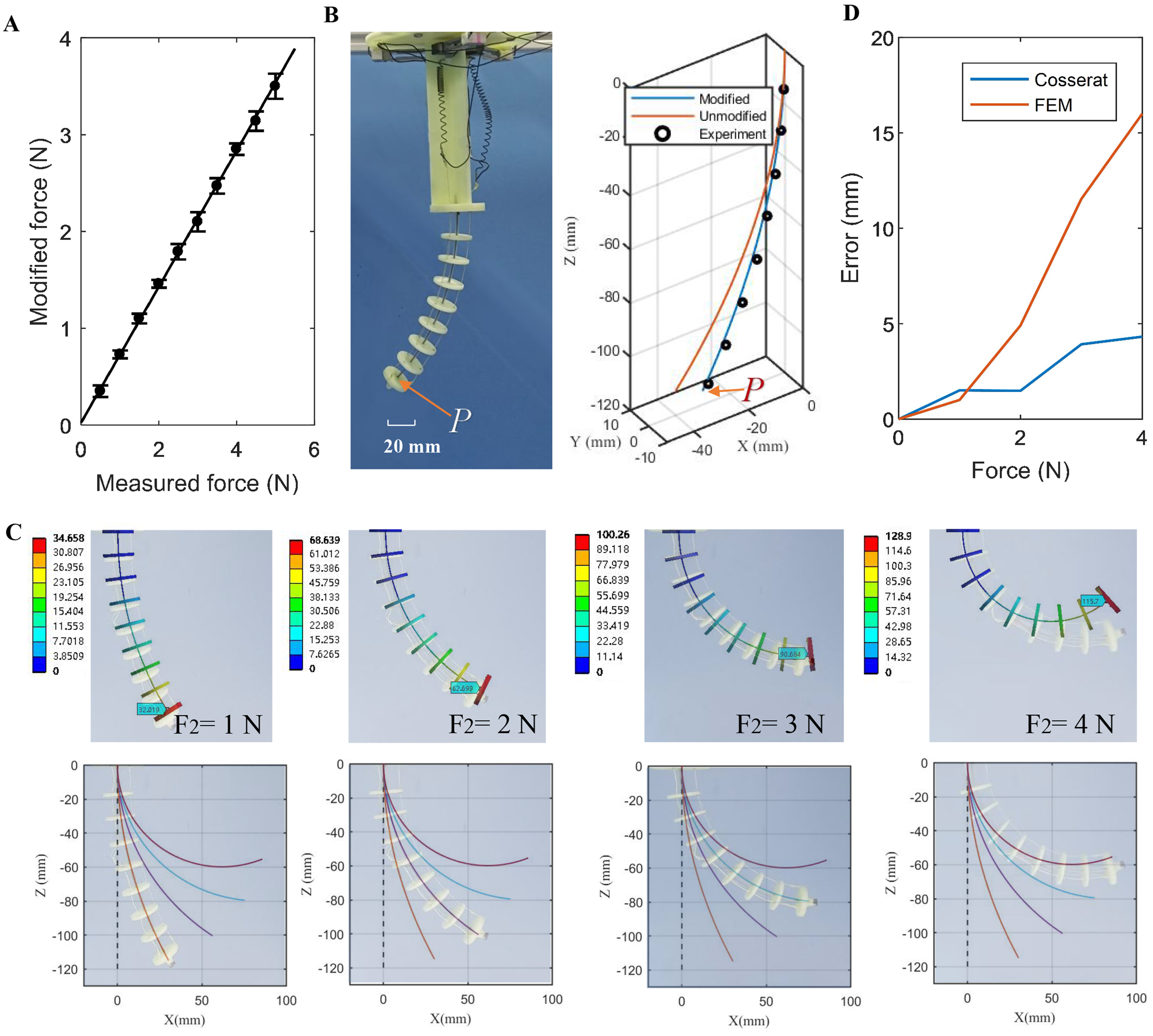
Figure 4. (A) Tension modification of the continuum robot; (B) Shape estimation of the continuum robot based on tension (F1 = 0, F2 =
where FL is the force measured by the load cell.
As shown in Figure 4B, the actual bending shape (black dots) of the robot was reconstructed from displacement data measured at eight connection points between disks along the backbone. The modeled bending shape (blue line) from Equation (10) demonstrates significantly higher accuracy using the modified tension-based forward kinematics model compared to the unmodified approach. For instance, the average positional errors (ΔE) for point P were 3.34 mm with tension modification vs. 11.65 mm without modification.
As shown in Figure 4C, a 3D FEM model was developed to predict the continuum robot’s bending shape, with disk material modeled as plastic and backbone material as superelastic SMA. The robot’s bending in the XOZ plane was simulated with SMA2 actuated by input forces ranging from 0 to 4 N. These FEM results were compared against the proposed forward kinematics model. Both models show close agreement with experimental data when accounting for weight and material factors. For quantitative comparison, the average positional errors (ΔE) at point P between simulations and experiments were calculated. Figure 4D illustrates that ∆E increases with input force from 0 to 4 N, reaching maximum values of 16 mm for FEM vs. 4.3 mm for the proposed model. Consequently, the proposed model demonstrates superior shape prediction accuracy. This performance difference primarily stems from the FEM model’s inability to account for tendon-disk friction. Additionally, FEM required 30 min per simulation case and cannot provide inverse kinematics solutions, whereas the proposed method computes both forward and inverse kinematics in approximately 100 ms. In summary, the proposed method offers greater suitability for continuum robot shape sensing and control compared to FEM.
Shape sensing based on forward kinematics and experimental verification
As mentioned above, the shapes of the continuum robot can be predicted using the Cosserat model based on the tensions of three tendons. To further verify the model, various experiments were conducted using a continuum robot prototype with different tensions and external loading conditions. As shown in Figure 5A, the real shapes are compared with the simulation results when the continuum robot bends into different shapes in the XOZ plane. The error increases gradually as the tension of the SMA1 spring increases from 0.5 to 5 N. The average error ΔE of point P for each tension increases from 2.11 (1.76% of the length) to
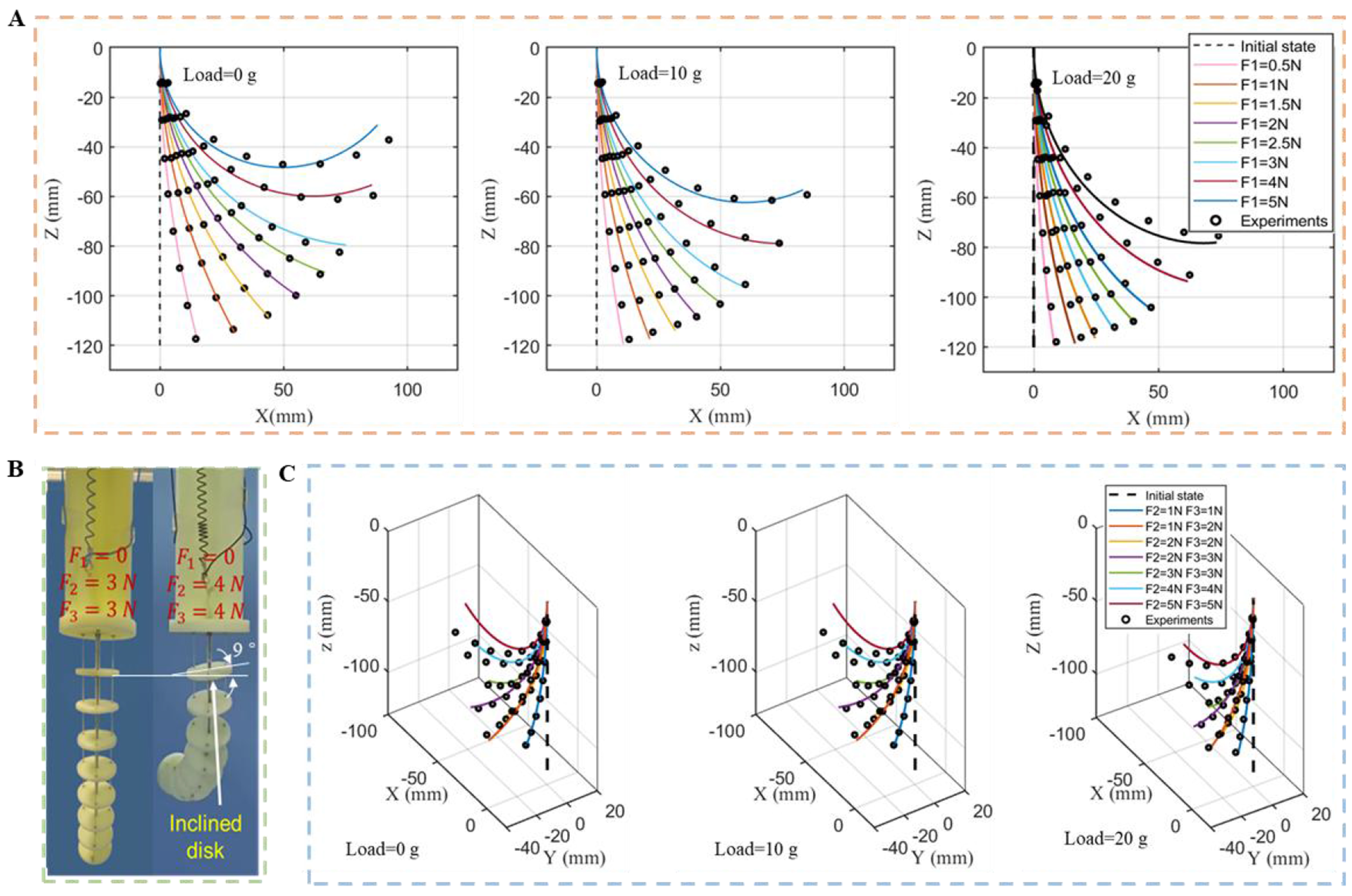
Figure 5. Shape sensing results based on the proposed model when only one or two SMA springs are actuated. (A) Bending in the XOZ plane; (B) Twisting deformation as the tension increases; (C) Bending in three-dimensional space. SMA: Shape memory alloy.
To evaluate the robot’s performance for complex 3D shapes, we experimentally tested the forward kinematics model predictions. To minimize the weight of the robotic arm, the disks were 3D-printed using lightweight plastic. Since the Cosserat model requires continuous curvature deformation, excessive disk thickness reduces the accuracy of the deformation model, necessitating minimal thickness. As shown in Figure 5B, experiments showed that with a 2 mm disk thickness, two SMA actuators applying 3 N of force produced virtually no tilt, while increasing the force to 4 N resulted in approximately 9° of tilt; when the thickness was reduced to 1 mm, only 3 N of force caused about 6° of tilt; with an increased thickness of
Shape sensing and control
To accurately sense and regulate the bending shape of the continuum robot, a control method based on Cosserat rod theory is applied to trajectory planning and tracking experiments. To increase the position tracking accuracy and robustness of SMA, many schemes based on hysteresis models of SMA have been proposed. Because SMA is very sensitive to temperature, it is difficult to obtain an accurate hysteresis model. Therefore, many model-free schemes, such as proportional integral derivative (PID) controllers and artificial neural networks, have been developed to increase the position tracking accuracy and robustness of SMA. Here, a closed-loop control method based on a radial basis function (RBF) is applied to compensate for the disturbance (hysteresis effect and unknown dynamics of the SMA actuator) and to achieve accurate bending shape control of a continuum robot. As shown in Figure 6, the block diagram of the control scheme implemented to control the robot can be divided into three parts. Part 1 corresponds to the method of calculating the tension in accordance with the inverse kinematics, which can be expressed as Equation (7) and Algorithm 2. Part 2 represents the tension control strategy based on RBF compensation. Part 3 represents the method of shape sensing in accordance with the forward kinematics, which is given in Algorithm 1.
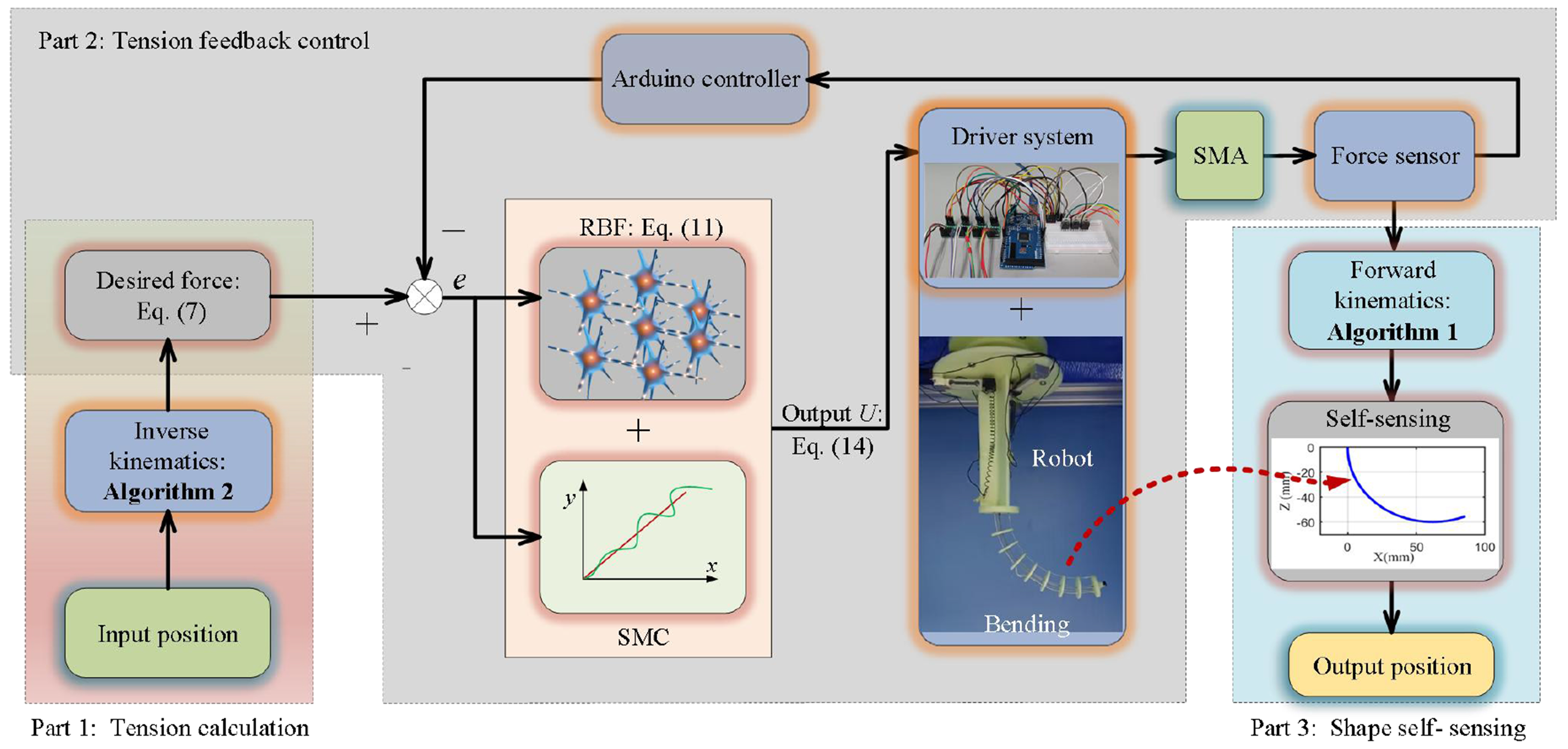
Figure 6. Block diagram of shape sensing and control for the continuum robot.
To accurately regulate the desired force, a proper prediction of the input signal based on RBF is used to calculate the output voltage to heat SMA springs. uRBF is the output of the RBF neural network, which can also be given as
Here, WT(k)H(k) is the linear output layer, n is the number of hidden-layer neurons, wn(k) is a hidden-layer-to-output interconnection weight, and hn(k) is the hidden layer with the RBF activation function, which can be expressed as
where X(k) is a vector of the input layer for the network. ||·|| denotes the Euclidean norm, Dn(k) is a vector of the center, and σn(k) is the width. For simplicity, the centers and widths are predefined and fixed. Therefore, Dn = [-1, 0.5, 2, 3.5, 5; -0.5, -0.25, 0, 0.25, 0.5], and σ1 = σ2, …, = σn = 35.
Here, the input layer X(k) can be expressed as
where e(k) = x(k) - xd(k) and
where s(k) = ce(k) +
where α = 0.05 is the learning rate. Detailed information about the RBR and SMC methods can be obtained from our previous research[35].
Then, after calculation using MATLAB (2018), the Arduino sends pulse width modulation (PWM) values to control the Metal-Oxide-Semiconductor Field-Effect Transistor (MOSFET) to amplify the input current of the SMA springs. The output force of the SMA springs measured by the tension sensors is used as the feedback of the control method. Finally, the shape of the continuum robot can be predicted according to the forward kinematics model.
RESULTS AND DISCUSSION
Before position control and shape sensing were simultaneously tested, part 2 was first examined alone to verify the effectiveness of the tension control strategy. Figure 7 shows the tracking results for a sinusoidal command 1.5 + sin(2πfx) with different frequencies f. As shown in Figure 7A, the maximum and mean errors of the proposed method with f = 1/27.6 Hz during the tracking period from 0 s to 200 s are 0.75 and 0.36 N, respectively. Figure 7B and C shows that at lower frequencies of f = 1/55.2 Hz and f = 1/82.8 Hz, the respective maximum errors are 0.3 and 0.13 N, and the respective mean errors are 0.09 and 0.04 N. These findings clearly demonstrate that the tension control strategy based on RBF compensation can lead to more precise tracking performance at low frequencies. The main reason is that the SMA springs cannot achieve a fast phase transformation from austenite to martensite due to the slow cooling speed. Since the tracking performance of the SMA springs at high frequencies is worse, it is necessary to test the position tracking performance at low frequencies in the following tests.
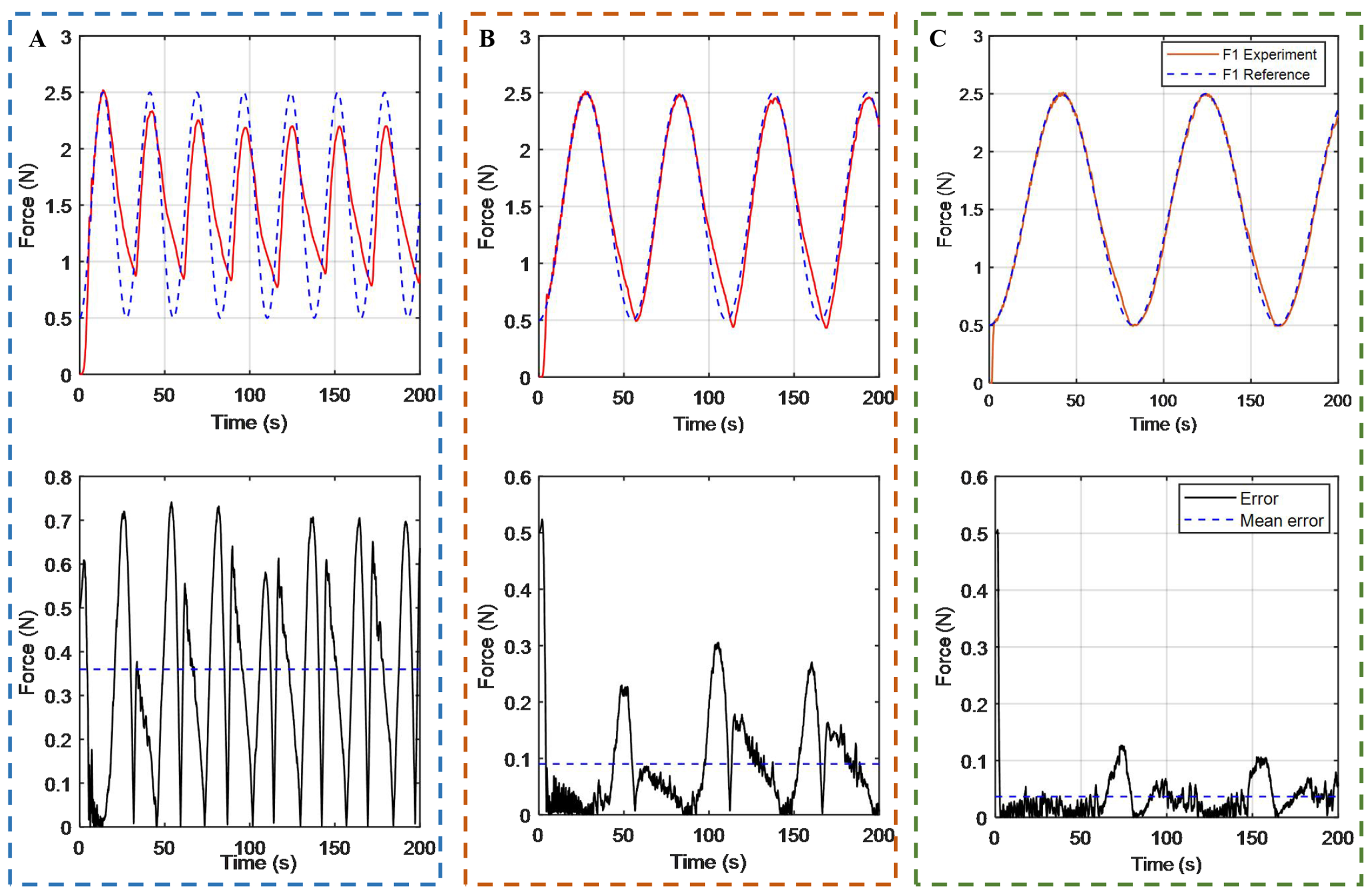
Figure 7. Tension tracking performance and errors at different frequencies. (A) Frequency f = 1/27.6 Hz; (B) Frequency f = 1/55.2 Hz; (C) Frequency f = 1/82.8 Hz.
To verify the proposed control method, several different experiments are conducted to track complex trajectories for the continuum robot. Figure 8A shows the method of obtaining the “heart” trajectory in the workspace. The “heart” trajectory is drawn in the XOY plane (Z = 0) first, followed by obtaining the “heart” trajectory projection consisting of a sequence of points in the workspace (curved surface consisting of discrete points) of the continuum robot. Then, these points (approximately 1,742 in total) can be used as input reference positions for trajectory tracking control. As shown in Figure 8B-D, the continuum robot can achieve accurate position tracking results for the “heart” trajectory. The maximum ratio of the position error to the robot’s length is 3.1% at 61 s, and the average value is 0.72%. The maximum error is primarily attributed to the tension coupling effects among multiple SMA driving units during trajectory abrupt-change phases. When the target configuration undergoes rapid switching, the thermomechanical response hysteresis of individual actuators introduces phase differences in tension adjustments. Such nonlinear interactions lead to dynamic compensation lag in the system, consequently resulting in error accumulation. Figure 8E and F shows the tension tracking performance and errors of the SMA springs, respectively. More details can be found in Supplementary Video 1.
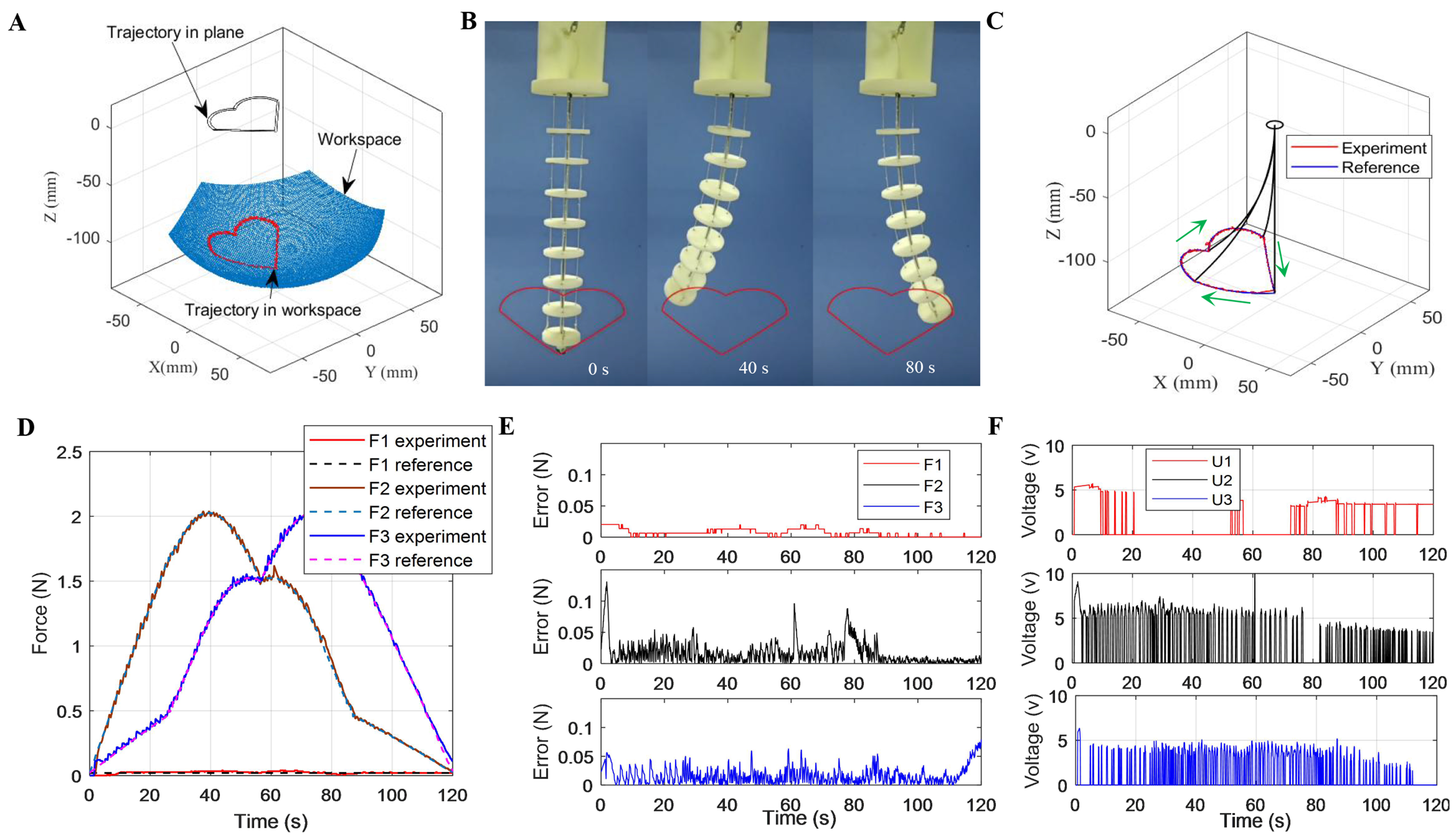
Figure 8. “Heart” trajectory tracking results. (A) Trajectory generation in the workspace; (B) Experimental photos; (C) “Heart” trajectory planning and tracking results; (D) Ratio of the position tracking error to the robot’s length; (E) Tensions of the SMA springs; (F) Tension tracking errors. SMA: Shape memory alloy.
As shown in Figure 9, the continuum robot can also complete “WHUT” (abbreviation for Wuhan University of Technology) trajectory tracking. Figure 9A-D shows the quantitative comparisons of the desired paths (blue lines) and the tracked trajectories (red lines). The maximum ratios of the position error to the robot’s length are 13.8%, 7.7%, 6.7% and 7.8% for the letters “W”, “H”, “U”, and “T”, respectively. These experimental results demonstrate the effectiveness of the proposed shape sensing and trajectory tracking strategy. More details can be found in Supplementary Video 2.
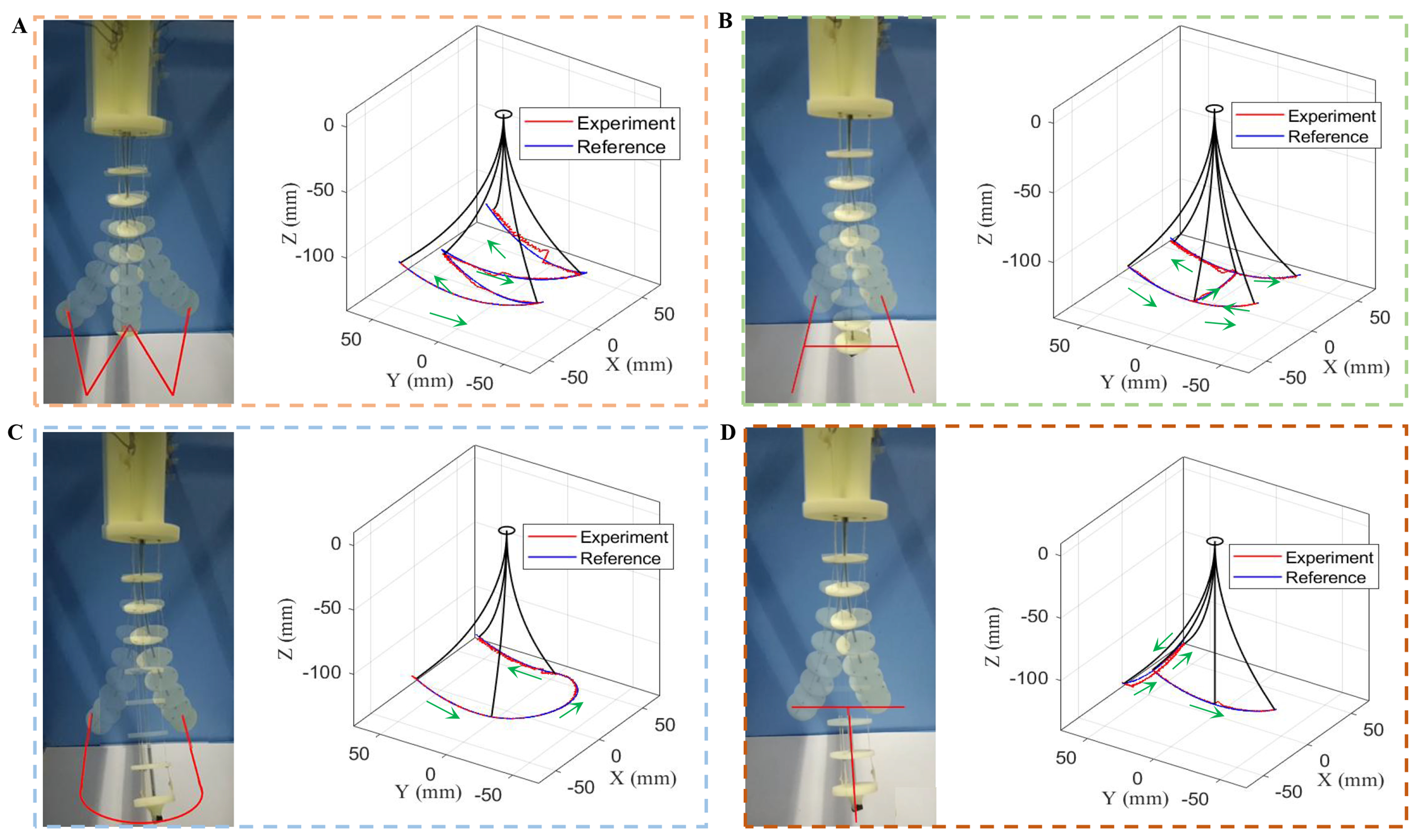
Figure 9. “Letters” trajectory tracking results. (A) “W” tracking performance; (B) “H” tracking performance; (C) “U” tracking performance; (D) “T” tracking performance.
As shown in Figure 10A, the continuum robot can automatically measure the weight of objects. By solving the forward kinematics of the proposed model, the loaded shapes can be estimated according to the tensions and weight at the tip. As shown in Figure 10B and C, the continuum robot can achieve accurate position tracking results for a “circle” trajectory with a 10 g weight and for a “square” trajectory with a 20 g weight. More details can be found in Supplementary Videos 3-5. Although the robot can accurately measure loads within 100 g, the maximum load for precise trajectory motion should be limited to below 20 g due to constraints in SMA driving force and structural rigidity; it can measure dynamic load weights, but load variations cause changes in the end-effector operational space and SMA driving force, therefore subsequent research will establish a relationship model between the load, operational space, and driving force to lay the foundation for precise trajectory control under dynamic loads.
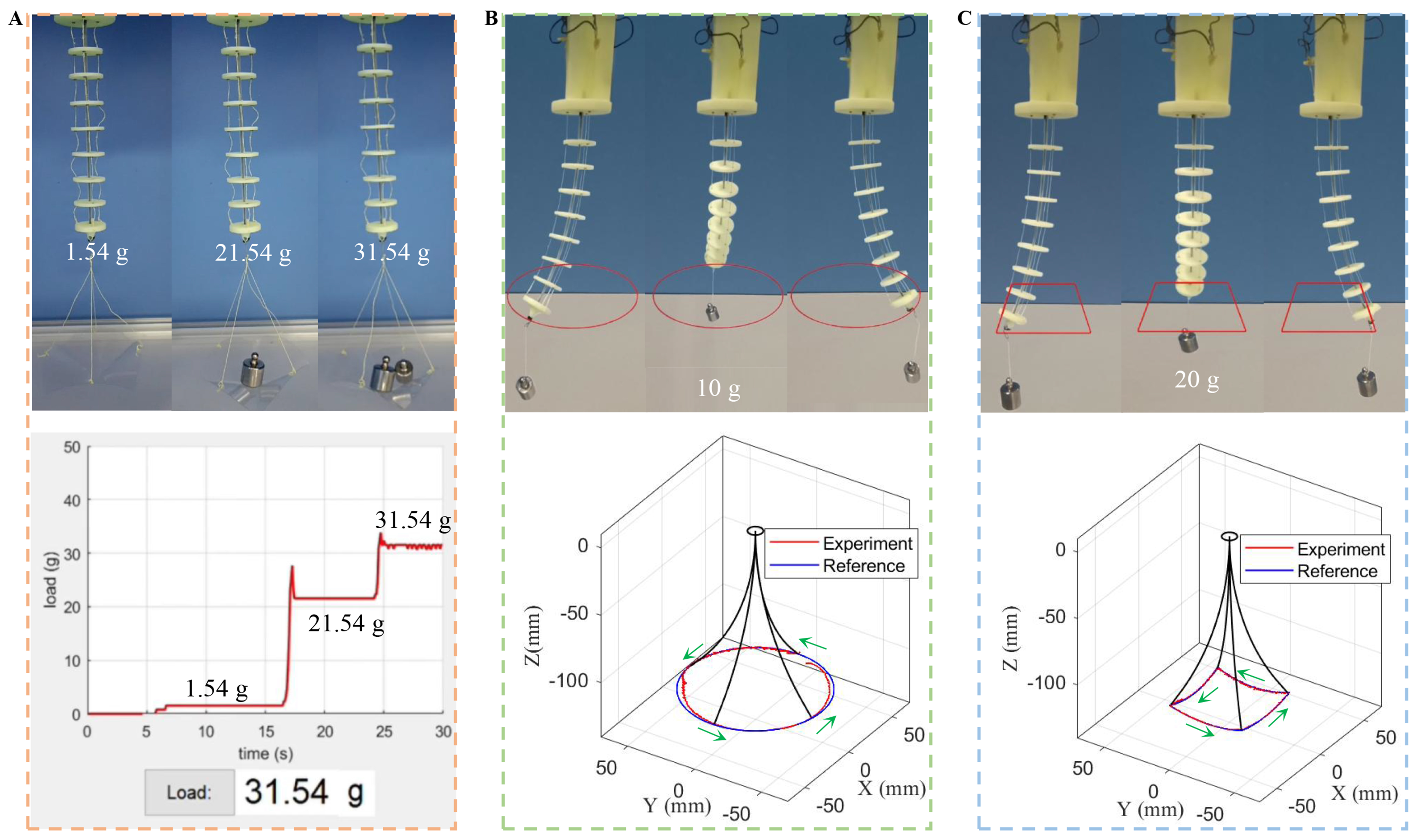
Figure 10. Trajectory tracking under load. (A) Load weight sensing; (B) Tracking results with a load of 10 g; (C) Tracking results with a load of 20 g.
As shown in Figure 11A, the continuum robot can grasp a ball using a suction unit actuated by the pump (connected with the tube), handle it while passing through a confined space, and drop it at the target position. As shown in Figure 11B, two robots can handle an object based on collaborative operation for complex task. More details can be found in Supplementary Videos 6 and 7. However, some disadvantages need to be mentioned. First, the workspace of the continuum robot is limited due to the use of one single segment design, and our future work will develop a multi-segment robot for a larger workspace and complex tasks. Second, compared with motors and pumps, SMA actuators have the advantages of a high power-to-weight ratio, small size and silence but suffer from slow response speed. Ongoing work will aim to improve the actuation frequency by using SMA springs with thin diameters.
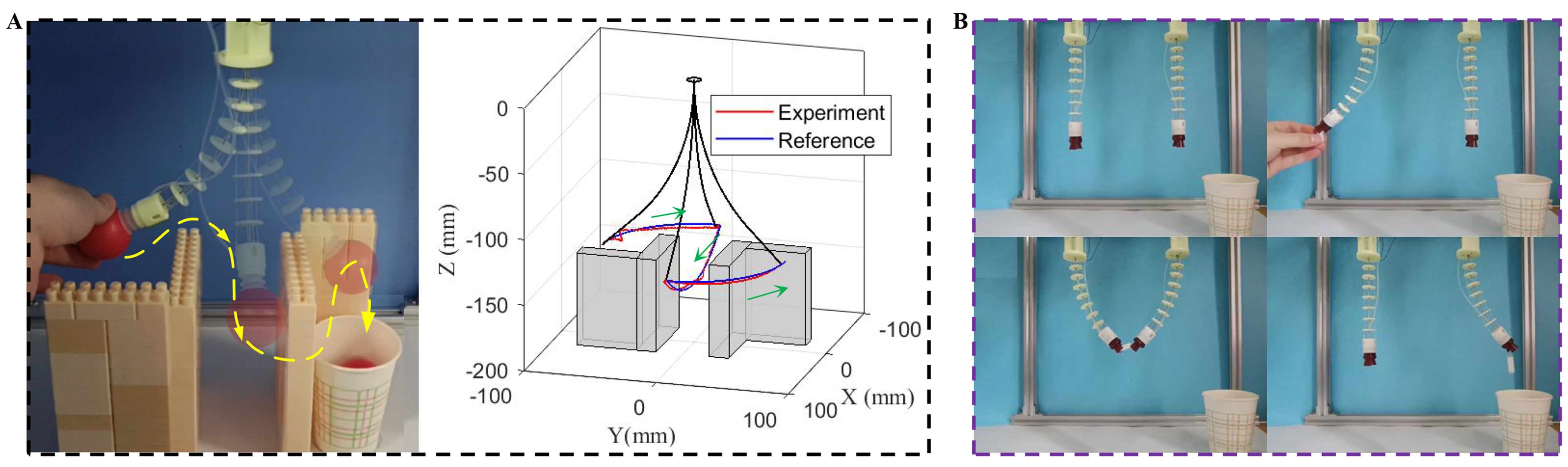
Figure 11. Object manipulation of robots. (A) Experiments and simulations of single robot; (B) cooperation of dual robots.
CONCLUSIONS
In this paper, we propose a method to simultaneously sense and control the 3D deformation of a continuum robot actuated by three SMA springs. Compared with shape sensing methods using strain, vision, EMF and FBG sensors based on CC assumptions, the proposed method can more accurately predict the bending shape of a continuum robot even under an unknown external load. Furthermore, relative to robots actuated by motors and pumps, the presented continuum robot possesses a simple and light structure and achieves excellent compliance and elasticity through the use of two different types of SMA. SMA usually can achieve a fatigue life of 106 cycles at strain levels below 4% without overload. However, high-frequency loading
To address the challenge of precise control over deformation in continuum robots caused by end-effector loads, this system enables accurate perception and control of body deformation by measuring end-load weight and applying Cosserat rod theory. This method provides reliable technical support for applications such as foreign object retrieval within slender curved pipelines, narrow-space inspection in radiation-prone nuclear power equipment (where SMA exhibits high radiation resistance), and deep-cavity surgeries in the human body (e.g., tumor removal).
DECLARATIONS
Authors’ contributions
Conceptualization: Li, J.; Huang, Y.
Methodology, writing - original draft preparation, writing - review and editing: Peng, Y.; Bian, J.; Ji, J.; Li, J.; Huang, Y.
Availability of data and materials
Data is available upon request from the corresponding author.
Financial support and sponsorship
This work was supported in part by the National Natural Science Foundation of China under Grant 52525502, 52188102 and 52175510, in part by the China Institute of Atomic Energy (No. KFZC2021010301), and in part by Hubei Provincial Natural Science Foundation of China under Grant 2023AFA085.
Conflicts of interest
Huang, Y. is the Editor-in-Chief of Soft Science. However, Huang, Y. was not involved in any steps of the editorial process, including reviewer selection, manuscript handling, or decision-making. All authors declared that there are no conflicts of interest.
Ethical approval and consent to participate
Not applicable.
Consent for publication
Not applicable.
Copyright
© The Author(s) 2025.
Supplementary Materials
REFERENCES
1. Fukuoka, Y.; Otaka, K.; Takeuchi, R.; Shigemori, K.; Inoue, K. Mechanical designs for field undulatory locomotion by a wheeled snake-like robot with decoupled neural oscillators. IEEE. Trans. Robot. 2023, 39, 959-77.
2. Huang, X.; Zou, J.; Gu, G. Kinematic modeling and control of variable curvature soft continuum robots. IEEE/ASME. Trans. Mechatron. 2021, 26, 3175-85.
3. Han, Z.; Liu, Z.; He, W.; Li, G. Distributed parameter modeling and boundary control of an octopus tentacle-inspired soft robot. IEEE. Trans. Contr. Syst. Technol. 2022, 30, 1244-56.
4. Zhang, B.; Fan, Y.; Yang, P.; Cao, T.; Liao, H. Worm-like soft robot for complicated tubular environments. Soft. Robot. 2019, 6, 399-413.
5. Blumenschein, L. H.; Koehler, M.; Usevitch, N. S.; Hawkes, E. W.; Rucker, D. C.; Okamura, A. M. Geometric solutions for general actuator routing on inflated-beam soft growing robots. IEEE. Trans. Robot. 2022, 38, 1820-40.
6. Xiong, W.; Feng, H.; Liwang, H.; et al. Multifunctional tactile feedbacks towards compliant robot manipulations via 3D-shaped electronic skin. IEEE. Sensors. J. 2022, 22, 9046-56.
7. Hawkes, E. W.; Blumenschein, L. H.; Greer, J. D.; Okamura, A. M. A soft robot that navigates its environment through growth. Sci. Robot. 2017, 2, eaan3028.
8. Kim, Y.; Yuk, H.; Zhao, R.; Chester, S. A.; Zhao, X. Printing ferromagnetic domains for untethered fast-transforming soft materials. Nature 2018, 558, 274-9.
9. Fang, G.; Matte, C.; Scharff, R. B. N.; Kwok, T.; Wang, C. C. L. Kinematics of soft robots by geometric computing. IEEE. Trans. Robot. 2020, 36, 1272-86.
10. Huang, X.; Zhu, X.; Gu, G. Kinematic modeling and characterization of soft parallel robots. IEEE. Trans. Robot. 2022, 38, 3792-806.
11. Gong, Z.; Fang, X.; Chen, X.; et al. A soft manipulator for efficient delicate grasping in shallow water: modeling, control, and real-world experiments. Int. J. Robot. Res. 2021, 40, 449-69.
12. Xu, Y.; Song, D.; Zhang, Z.; Wang, S.; Shi, C. A novel extensible continuum robot with growing motion capability inspired by plant growth for path-following in transoral laryngeal surgery. Soft. Robot. 2024, 11, 171-82.
13. Troncoso, D. A.; Robles-Linares, J. A.; Russo, M.; et al. A continuum robot for remote applications: from industrial to medical surgery with slender continuum robots. IEEE. Robot. Automat. Mag. 2023, 30, 94-105.
14. Tao, Y.; Han, F.; Shi, C.; Yang, R.; Chen, Y.; Ren, Y. Liquid metal-based flexible and wearable sensor for functional human-machine interface. Micromachines 2022, 13, 1429.
15. Xu, Y.; Su, Y.; Xu, X.; et al. Porous liquid metal-elastomer composites with high leakage resistance and antimicrobial property for skin-interfaced bioelectronics. Sci. Adv. 2023, 9, eadf0575.
16. Thuruthel, T. G.; Shih, B.; Laschi, C.; Tolley, M. T. Soft robot perception using embedded soft sensors and recurrent neural networks. Sci. Robot. 2019, 4, eaav1488.
17. Li, D.; Wang, H.; Han, Z.; et al. Anisotropic structural carbon nanotube aerogels for piezoresistive strain sensors with multidirectional sensitivity. Compos. Part. B. Eng. 2025, 291, 112028.
18. Pradela-Filho, L. A.; Andreotti, I. A.; Carvalho, J. H.; et al. Glass varnish-based carbon conductive ink: a new way to produce disposable electrochemical sensors. Sens. Actuators. B. Chem. 2020, 305, 127433.
19. Truby, R. L.; Wehner, M.; Grosskopf, A. K.; et al. Soft somatosensitive actuators via embedded 3D printing. Adv. Mater. 2018, 30, e1706383.
20. Yu, H.; Bian, J.; Chen, F.; Ji, J.; Huang, Y. Ultrathin, graphene-in-polyimide strain sensor via laser-induced interfacial ablation of polyimide. Adv. Elect. Mater. 2023, 9, 2201086.
21. Mbakop, S.; Tagne, G.; Drakunov, S.; Merzouki, R. Parametric PH curves model based kinematic control of the shape of mobile soft manipulators in unstructured environment. IEEE. Trans. Ind. Electron. 2022, 69, 10292-300.
22. Duan, L.; Aragon-Camarasa, G. A continuous robot vision approach for predicting shapes and visually perceived weights of garments. IEEE. Robot. Autom. Lett. 2022, 7, 7950-7.
23. Song, S.; Ge, H.; Wang, J.; Meng, M. Q. Real-time multi-object magnetic tracking for multi-arm continuum robots. IEEE. Trans. Instrum. Meas. 2021, 70, 1-9.
24. Li, T.; Qiu, L.; Ren, H. Distributed curvature sensing and shape reconstruction for soft manipulators with irregular cross sections based on parallel dual-FBG arrays. IEEE/ASME. Trans. Mechatron. 2020, 25, 406-17.
25. Gao, A.; Lin, Z.; Zhou, C.; et al. Body contact estimation of continuum robots with tension-profile sensing of actuation fibers. IEEE. Trans. Robot. 2024, 40, 1492-508.
26. Zhong, L.; Tian, X.; Wang, J.; et al. Calibration-free optical waveguide bending sensor for soft robots. Soft. Sci. 2025, 5, 3.
27. Rucker, D. C.; Webster Iii, R. J. Statics and dynamics of continuum robots with general tendon routing and external loading. IEEE. Trans. Robot. 2011, 27, 1033-44.
28. Till, J.; Aloi, V.; Rucker, C. Real-time dynamics of soft and continuum robots based on Cosserat rod models. Int. J. Robot. Res. 2019, 38, 723-46.
29. Ay, M. Modeling and analysis of a modular-structured tendon-driven continuum robot for the three-dimensional end effector coordinate. Simul. Model. Pract. Theory. 2023, 127, 102787.
30. Zhao, W.; Liu, L.; Lan, X.; Leng, J.; Liu, Y. Thermomechanical constitutive models of shape memory polymers and their composites. Appl. Mech. Rev. 2023, 75, 020802.
31. Li, J.; Huang, Y. Design and control of turtle locomotion-inspired robots actuated by antagonistic shape memory alloy springs. IEEE/ASME. Trans. Mechatron. 2022, 27, 4851-62.
32. An, X.; Cui, Y.; Sun, H.; Shao, Q.; Zhao, H. Active-cooling-in-the-loop controller design and implementation for an SMA-driven soft robotic tentacle. IEEE. Trans. Robot. 2023, 39, 2325-41.
33. Chen, Y.; Wu, B.; Jin, J.; Xu, K. A variable curvature model for multi-backbone continuum robots to account for inter-segment coupling and external disturbance. IEEE. Robot. Autom. Lett. 2021, 6, 1590-7.
34. Renda, F.; Boyer, F.; Dias, J.; Seneviratne, L. Discrete cosserat approach for multisection soft manipulator dynamics. IEEE. Trans. Robot. 2018, 34, 1518-33.
Cite This Article
How to Cite
Download Citation
Export Citation File:
Type of Import
Tips on Downloading Citation
Citation Manager File Format
Type of Import
Direct Import: When the Direct Import option is selected (the default state), a dialogue box will give you the option to Save or Open the downloaded citation data. Choosing Open will either launch your citation manager or give you a choice of applications with which to use the metadata. The Save option saves the file locally for later use.
Indirect Import: When the Indirect Import option is selected, the metadata is displayed and may be copied and pasted as needed.
About This Article
Special Issue
Copyright

Data & Comments
Data
0


Comments
Comments must be written in English. Spam, offensive content, impersonation, and private information will not be permitted. If any comment is reported and identified as inappropriate content by OAE staff, the comment will be removed without notice. If you have any queries or need any help, please contact us at [email protected].