



Search-based hierarchical whole-body motion planning and control for quadrotors
 0
0 
Abstract
In this paper, we propose a novel search-based hierarchical whole-body motion planning framework that can divide the planning process of a quadrotor into two parts: position-only planning and attitude-aware planning. A safe flight corridor (SFC) containing spatial scale information is designed to partition collision-free regions to identify narrow regions in the environment, and the attitude-aware planning process is triggered only in narrow regions. Based on the spatial-scale SFC, a carefully designed hierarchical collision detection mechanism can constrain the attitude of the quadrotor along the trajectory to the safe corridor to ensure collision-free and accelerate the planning process. Afterward, a trajectory refinement strategy is introduced to preserve the searched safe attitude-aware trajectory segments and optimize the neighboring position-only trajectory segments with position, velocity, and acceleration continuity, ensuring smooth transitions between different planning stages. Subsequently, a differentially flat model predictive controller is used to track aggressive trajectories. Benchmark results show that the proposed method generates safe and aggressive trajectories while reducing computation time by approximately 4-9 times relative to the search-based whole-body baseline. High-fidelity simulation experiments are conducted in various unknown environments to demonstrate the feasibility of the generated trajectories.
Keywords
1. INTRODUCTION
Quadrotors have attracted much attention in the field of aircraft due to their flexible maneuverability and diverse application scenarios. Traditional quadrotor flight motion planning achieves obstacle avoidance by modeling the quadrotor as a sphere or simply inflating the obstacles. The resulting trajectory is relatively conservative and is mainly used for low-speed, stable flight missions[1-5]. However, when performing tasks such as high-maneuverability flight, stunts, or dealing with dynamic obstacles in complex environments, quadrotors need to adjust their attitude to pass through narrow gaps that are much smaller than themselves, as shown in Figure 1. In such scenarios, motion planning must be carried out in the full configuration space, where both position and orientation are considered, which significantly increases planning complexity.
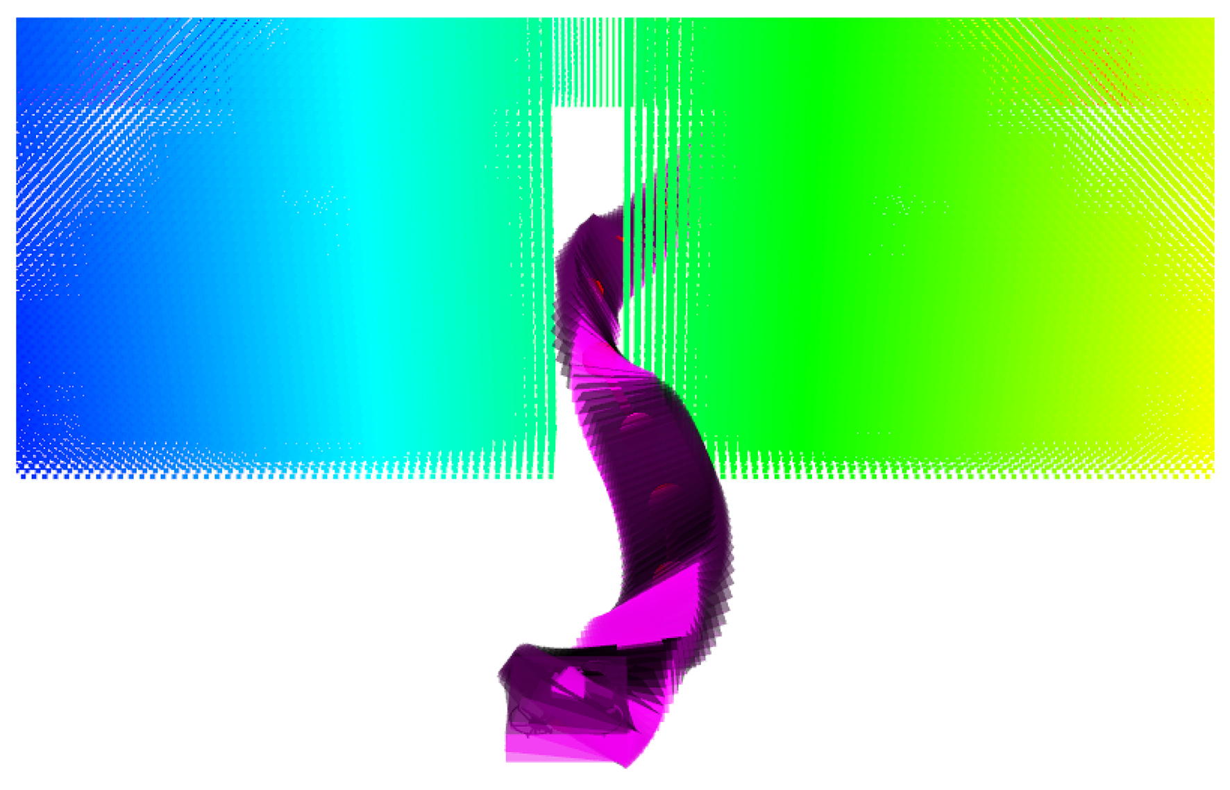
Figure 1. By finely dividing the environment into safe corridors with spatial scale information, our method can separate attitude-aware planning from position-only planning, which can greatly speed up the search efficiency compared with existing methods.
Whole-body motion planning is crucial for applications such as quadrotor navigation[6], robotic manipulation[7], and vehicle control. Unlike simpler motion planning in Euclidean space, where only point-mass objects are considered[8], whole-body motion planning involves additional complexity because rotational motion must also be taken into account. Despite recent progress, whole-body motion planning for quadrotors still faces three main challenges.
(1) Efficient extraction and characterization of feasible regions. Whole-body motion planning relies on environmental perception and free-space representation to identify regions where the quadrotor attitude must be explicitly considered. Some methods use onboard cameras to detect narrow regions[9], but they typically rely on specific gap geometries or visual features. Other methods require external motion-capture systems to obtain prior position and orientation information of narrow gaps[6,10], limiting their applicability in unstructured environments. Another line of work models obstacles or feasible regions using convex polyhedra[11,12]. However, high-quality convex decomposition can be computationally expensive. Voronoi-based methods[13] can also partition the feasible space and provide safe paths with large clearance, but they are often conservative. Safe flight corridors (SFCs)[14-16] have been widely adopted for quadrotor trajectory generation because they provide compact convex constraints for optimization. Nevertheless, conventional SFCs usually describe only the geometric boundary of the collision-free space and lack explicit spatial-scale information, making it difficult to distinguish spacious regions suitable for position-only planning from narrow regions that require attitude-aware planning.
(2) Real-time whole-body motion planning. Existing whole-body motion planning methods can be broadly classified into search-based methods[9,17], learning-based methods[18,19], and optimization-based methods[6,10,12,20]. Search-based methods generate motion primitives by sampling the control space to find feasible trajectories. Liu et al. modeled the quadrotor as an ellipsoid and detected collisions by testing whether obstacle points lie inside it[17]. Although finer sampling can improve feasibility, the search may require several seconds, while sampling in jerk space to ensure acceleration continuity leads to the curse of dimensionality. Learning-based methods have shown promising performance in narrow-gap traversal. Wu et al. proposed a pixel-to-action policy using reinforcement learning[18], while Zhang et al. developed a differentiable-simulation-based end-to-end framework for irregular gaps[19]. However, such methods typically require extensive simulation training and careful reward design, and may face generalization challenges in unseen cluttered environments. Optimization-based methods typically use convex decomposition to generate SFCs at the front end and optimize trajectory smoothness, safety, and dynamic feasibility at the back end[6,10,12,20]. However, imposing attitude constraints along the entire trajectory increases the computational burden. Therefore, a real-time model-based framework that exploits spatial-scale information and selectively activates attitude-aware planning in narrow regions remains necessary.
(3) Real-time control with constraints. Conventional quadrotor tracking controllers usually adopt a cascaded feedback structure for position and attitude tracking. However, dynamic constraints are typically not explicitly handled in the control layer, placing a heavy burden on the planning module[21-23]. If the reference trajectory violates the dynamic limits of the quadrotor, the controller may suffer from large tracking errors or even tracking failure. Model predictive control (MPC) is a widely used strategy for explicitly handling dynamic constraints by predicting future states and optimizing control inputs online[24]. However, quadrotor dynamics are inherently nonlinear, especially during aggressive flight with large roll and pitch angles. Directly applying nonlinear MPC to such systems requires solving a constrained nonlinear optimization problem at each control step, which can introduce considerable computational burden. When high-dimensional states, input limits, and fast control frequencies are considered simultaneously, the resulting nonlinear MPC problem may be difficult to solve in real time, thereby limiting its applicability as a high-frequency control module for aggressive quadrotor motion.
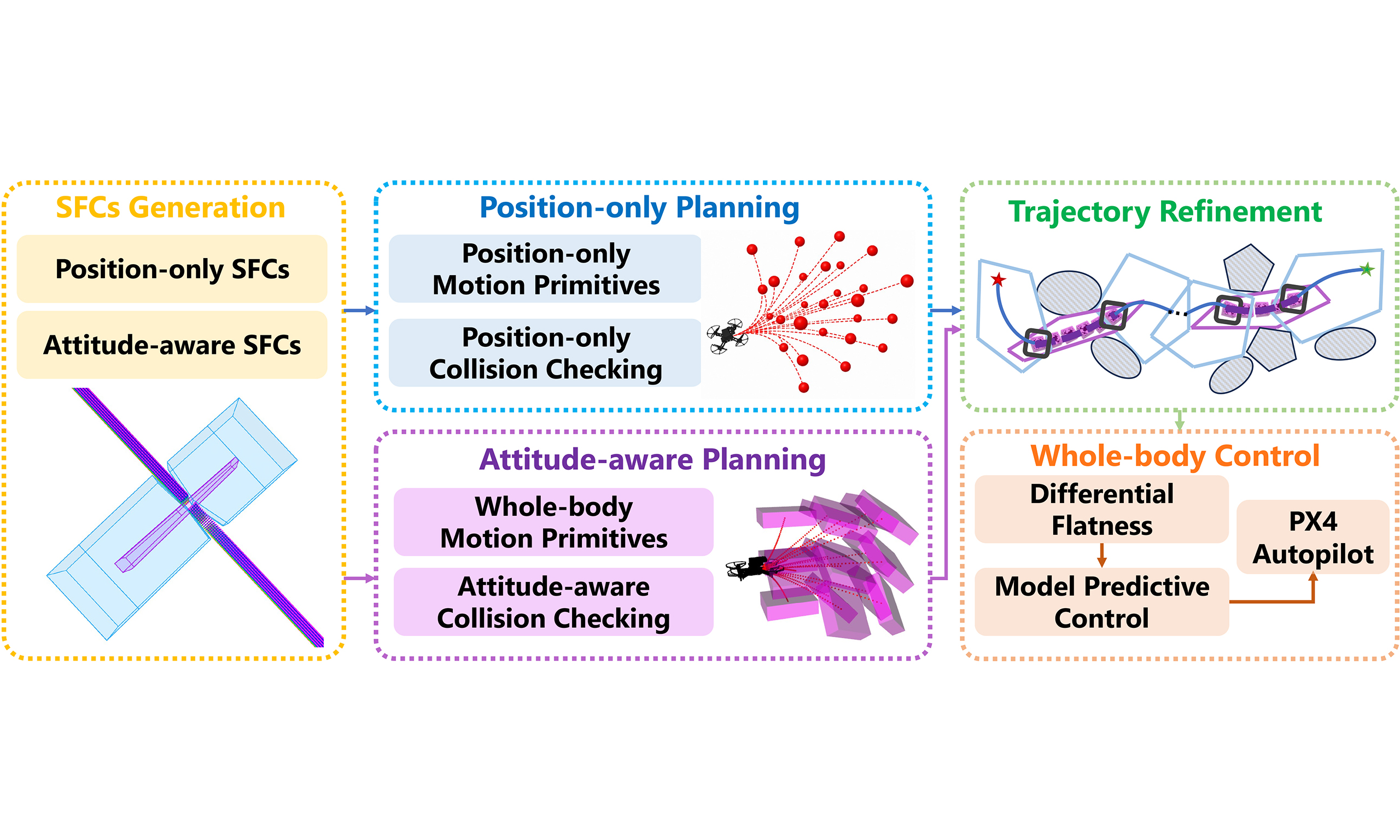
To address these challenges, we develop a search-based hierarchical whole-body motion planning and control framework for quadrotors. First, a spatial-scale-aware SFC strategy classifies the free space into spacious regions suitable for position-only planning and narrow regions requiring attitude-aware planning. Attitude-aware whole-body collision checking is selectively activated only in narrow regions, reducing unnecessary state expansion and improving search efficiency. Next, attitude-aware trajectory segments are retained, while the neighboring position-only segments are refined subject to position, velocity, and acceleration continuity. Finally, a differentially flat model predictive controller (DF-MPC) is used to track the resulting aggressive trajectory while explicitly enforcing dynamic constraints. The main contributions of this paper are summarized as follows:
• A spatial-scale-aware SFC generation method is proposed. Compared with widely used SFC generation methods[14-16], the proposed method not only provides geometric containment constraints for trajectory generation but also characterizes the local spatial scale of the free space. This information enables the environment to be classified into spacious regions suitable for position-only planning and narrow regions requiring attitude-aware planning.
• A hierarchical collision-checking and trajectory-refinement mechanism is proposed. Using the spatial-scale information provided by the SFCs, attitude-aware whole-body collision checking is selectively activated in narrow regions, while efficient position-only collision checking is performed in spacious regions. The resulting attitude-aware trajectory segments are retained, whereas the neighboring position-only segments are refined to improve the higher-order continuity of the overall trajectory.
• A model predictive controller based on differential flatness is developed for whole-body trajectory tracking. The controller explicitly enforces dynamic constraints and maintains accurate tracking as the reference trajectory approaches the dynamic limits of the quadrotor. Its tracking performance is evaluated using the high-fidelity AirSim simulator.
The remainder of this paper is organized as follows. Section 2 introduces the differential flatness and collision-checking formulations. Section 3 presents the hierarchical whole-body motion planning and trajectory refinement methods. Section 4 develops the DF-MPC. Section 5 reports benchmark comparisons and high-fidelity simulation results. Finally, Section 6 concludes the paper.
2. PRELIMINARIES
2.1. Differential flatness and attitude reconstruction
The quadrotor has been shown to be a differentially flat system, whose state and control inputs can be represented by the flat output σ = [x, y, z, ψ]
where xb, yb, and zb are the body-frame axes expressed in the world frame. Let
Then, the body z-axis is aligned with the desired total force direction:
The desired yaw angle ψ defines an intermediate heading direction:
According to yb =
Finally, from xb =yb × zb, the body x-axis is obtained as
If the collective thrust f and the body angular velocity ω are used as control inputs, they can be computed from the flat outputs as
where
2.2. Collision checking
SFCs decompose the collision-free space into an ordered sequence of convex polyhedra. Each SFC is represented in half-space form as
where each row of A defines the normal vector of a supporting plane and the corresponding element of b defines its offset. Based on this representation, we introduce position-only and attitude-aware collision-checking conditions for various spatial regions.
2.2.1. Position-only collision checking
In regions with sufficient clearance, the quadrotor is approximated as a point mass, allowing collision checking to be performed using only its center position. Let the SFC associated with the i-th trajectory segment be
where
where p(t) denotes the position of the quadrotor center and Ti denotes the duration of the corresponding trajectory segment. This condition ensures that the quadrotor center remains within its associated SFC throughout the segment.
To maintain additional clearance from the SFC boundary, we introduce a safety distance dsafe > 0 and strengthen the position-only collision-free condition as
where the rows of Ai are normalized and
2.2.2. Attitude-aware collision checking
In narrow regions, a point-mass approximation is insufficient because the collision-free configuration of the quadrotor depends on its attitude. We therefore represent the quadrotor body as a convex polyhedron and perform attitude-aware collision checking using all its vertices. Let
The corresponding world-frame vertex coordinates at time t are
where R(t) ∈ SO(3) is the rotation matrix recovered from the differential-flatness mapping, p(t) is the position of the quadrotor center, and
Because both the quadrotor model and the SFC are convex, the entire quadrotor body lies within the i-th SFC if and only if all its vertices lie within that SFC. The attitude-aware collision-free condition can therefore be expressed as
Unlike the position-only condition in Equation (10), the attitude-aware condition explicitly accounts for attitude. Because the rotation matrix is derived from the planned acceleration and yaw angle, this condition captures the effect of acceleration-induced attitude changes and is applied in narrow regions where attitude adjustment is essential for collision-free traversal.
3. WHOLE-BODY MOTION PLANNING
In this section, we first present a method for generating whole-body motion primitives based on the geometry of the quadrotor and clarify the conditions required to ensure collision-free whole-body motion within convex polyhedra. We then propose a spatial-scale-aware SFC classification method to distinguish spacious regions suitable for position-only planning from narrow regions requiring attitude-aware planning. Finally, we develop a trajectory-refinement strategy to ensure continuous attitude transitions across trajectory segments.
3.1. Whole-body motion primitives
According to the differential flatness of the quadrotor, the system state and control input can be represented by a set of appropriately selected flat outputs σ = [x, y, z, ψ]
Consider an s-th-order integrator chain in the flat-output space. The state variable and control input are defined as
The corresponding state-space model is
Under a constant control input, each component of p(t) is represented by an s-th-order polynomial. By uniformly sampling the control space
To achieve whole-body obstacle avoidance, the geometry of the quadrotor must be considered. In[17], the quadrotor is modeled as an ellipsoid. To accommodate a more general body shape, we model it as a convex polyhedron. In particular, we use a cuboid with half-lengths along the three body axes denoted by dx, dy, and dz. Its body-frame occupied set is
Accordingly, its eight vertices are
According to the differential-flatness formulation introduced in Section 2.1, the rotation matrix R(t) is determined by the acceleration
Figure 2 shows whole-body motion primitives generated over a fixed duration τ by sampling the acceleration and jerk spaces.
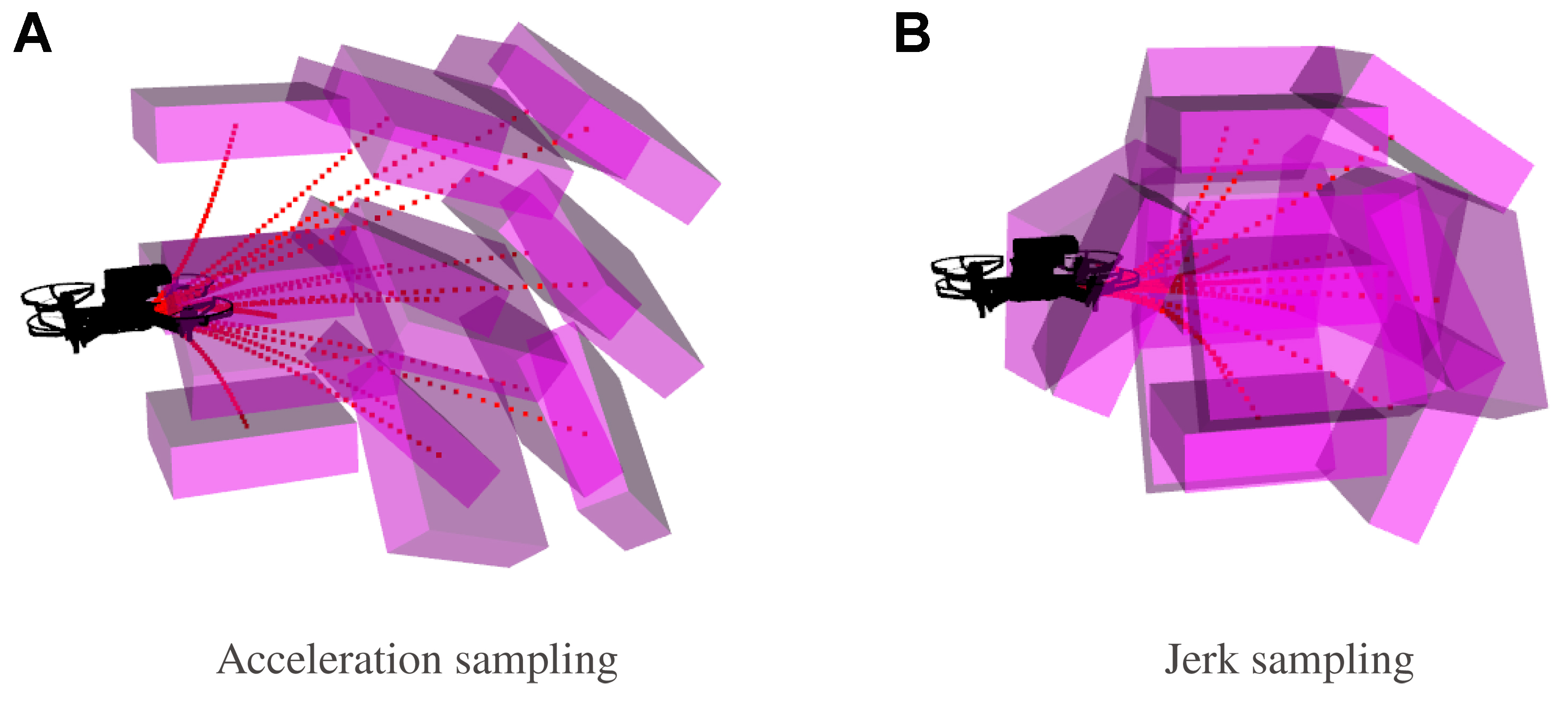
Figure 2. Examples of three-dimensional whole-body motion primitives starting from an initial state x0. (A and B) show the primitives generated by sampling the acceleration space (s = 2) and jerk space (s = 3), respectively. The purple cuboids represent the terminal whole-body states after applying a constant control input for τ = 0.2 s. The initial velocity and acceleration are v0 =[1, 0, 0]
The expansion cost of a motion primitive is defined as
where ρ is the time-penalty coefficient, which encourages faster trajectories. For a constant control input ud and a fixed sampling duration τ, the primitive cost becomes J(τ) = (||ud||22 + ρ)τ. At the same control resolution and sampling duration, jerk-controlled search ensures acceleration continuity but incurs substantially higher computational and memory costs as the system order increases. Because the attitude is directly related to acceleration, the proposed method adopts an acceleration-controlled system to improve search efficiency. The resulting acceleration discontinuities at the junctions of motion primitives are addressed by the trajectory-refinement method presented in Section 3.2.3.
3.2. Generation of a collision-free trajectory
This subsection introduces the generation of a collision-free trajectory. SFCs with spatial-scale information are used to divide the free space into Pos-SFCs and Att-SFCs. Efficient position-only planning is performed in Pos-SFCs, whereas attitude-aware planning is activated in Att-SFCs to explicitly account for attitude. After the search stage, a trajectory-refinement strategy is introduced to ensure continuous transitions between position-only and attitude-aware trajectory segments.
3.2.1. Generation of position-only and attitude-aware SFCs
To improve the efficiency of search-based whole-body planning, we construct an ordered sequence of SFCs along a center-feasible guide path. By restricting the expansion of motion primitives to these corridors, the proposed method avoids exploring redundant regions, thereby reducing the number of expanded nodes and the overall search time. SFCs generated in spacious and narrow regions generally exhibit substantially different spatial scales. This observation motivates us to divide the generated corridors into Pos-SFCs and Att-SFCs, as illustrated in Figure 3.
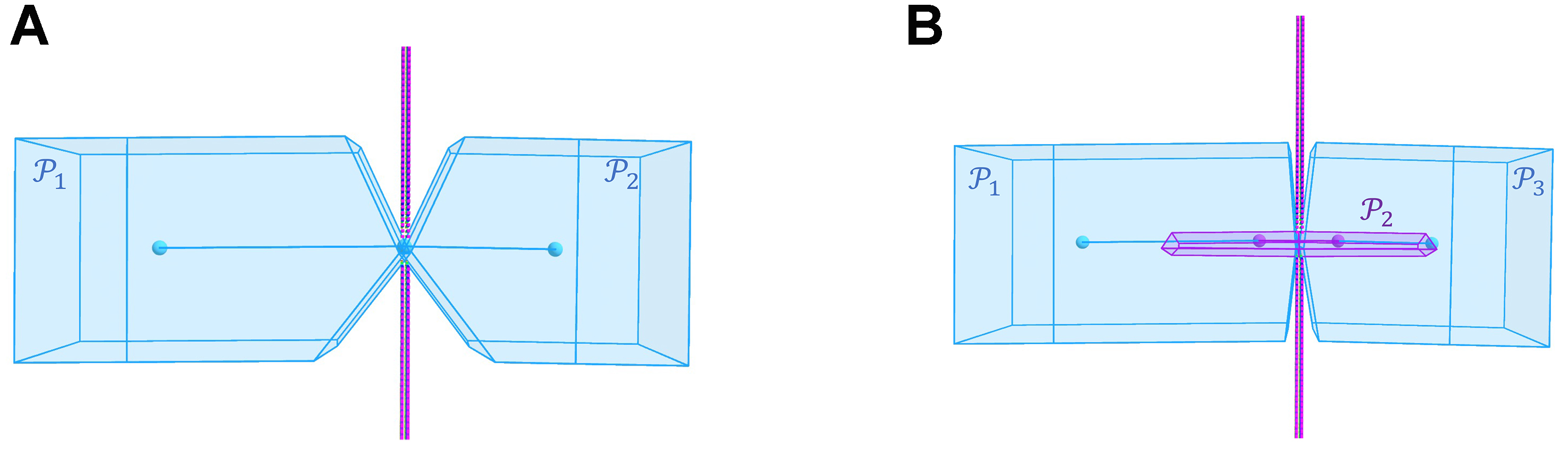
Figure 3. Comparison of corridor construction around a narrow passage. The blue points represent position-only seed endpoints, whereas the purple points represent attitude-aware seed endpoints. (A) The conventional method generates two polyhedra whose overlap is concentrated near the narrow opening, leaving insufficient space for attitude adjustment and corridor transition; (B) The proposed method inserts an Att-SFC
The guide path is first generated by a front-end path-searching algorithm and is represented as Γ = {q0, q1, …,
For each guide point qk, a radius query is performed on the obstacle-point KD-tree. The corresponding sphere-collision indicator is defined as
where
The resulting typed guide path is divided into seed segments, which are used to generate SFCs. Each generated SFC is directly inherited from its corresponding guide seed: position-only seeds generate Pos-SFCs, whereas attitude-aware seeds generate Att-SFCs. This construction restricts the translational search space while identifying regions in which attitude-aware whole-body planning may be required.
Figure 3 compares conventional corridor construction with the proposed typed-seed construction. The blue points represent the endpoints of position-only seeds, whereas the purple points represent the endpoints of attitude-aware seeds. In the conventional method shown in Figure 3A, a uniform seed-generation strategy produces two large polyhedra on opposite sides of the narrow passage. Their overlap is concentrated near the opening and does not provide sufficient space for attitude adjustment and corridor transition. In the proposed method shown in Figure 3B, the bounding-sphere test identifies the attitude-critical portion of the guide path. The purple attitude-aware seed generates the intermediate Att-SFC
3.2.2. Hierarchical collision checking
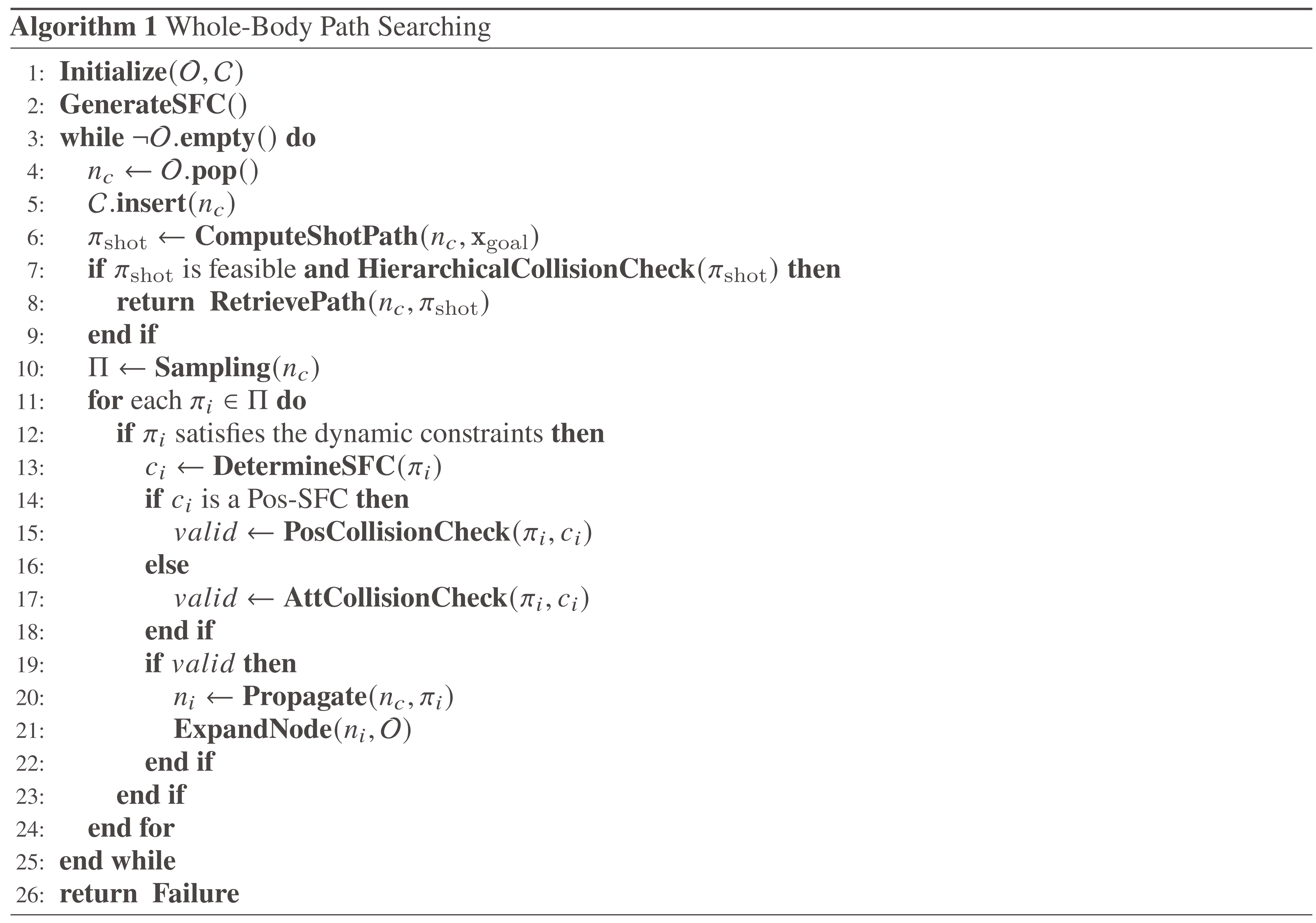
After obtaining the ordered SFC sequence, the search is restricted to the corresponding corridor regions, thereby avoiding the expansion of redundant nodes. This property also allows the computationally expensive attitude-aware collision checking to be separated from efficient position-only collision checking.
Specifically, PosCollisionCheck(·) determines whether the sampled positions of a motion primitive remain within its associated Pos-SFC according to Equation (11). In contrast, AttCollisionCheck(·) transforms all cuboid vertices according to the attitude and verifies their containment within the associated Att-SFC using Equation (14). Finally, the accepted primitives retain their corridor types for the subsequent trajectory-refinement stage.
Whole-body path searching is built upon the kinodynamic A* algorithm for quadrotors[3], as summarized in Algorithm 1. The open and closed lists are denoted by
Algorithm 1.
Figure 4 illustrates the hierarchical whole-body motion-planning mechanism. The blue convex polyhedron denotes a Pos-SFC, in which a position-only trajectory is generated, whereas the purple convex polyhedron denotes an Att-SFC, in which an attitude-aware trajectory is generated.
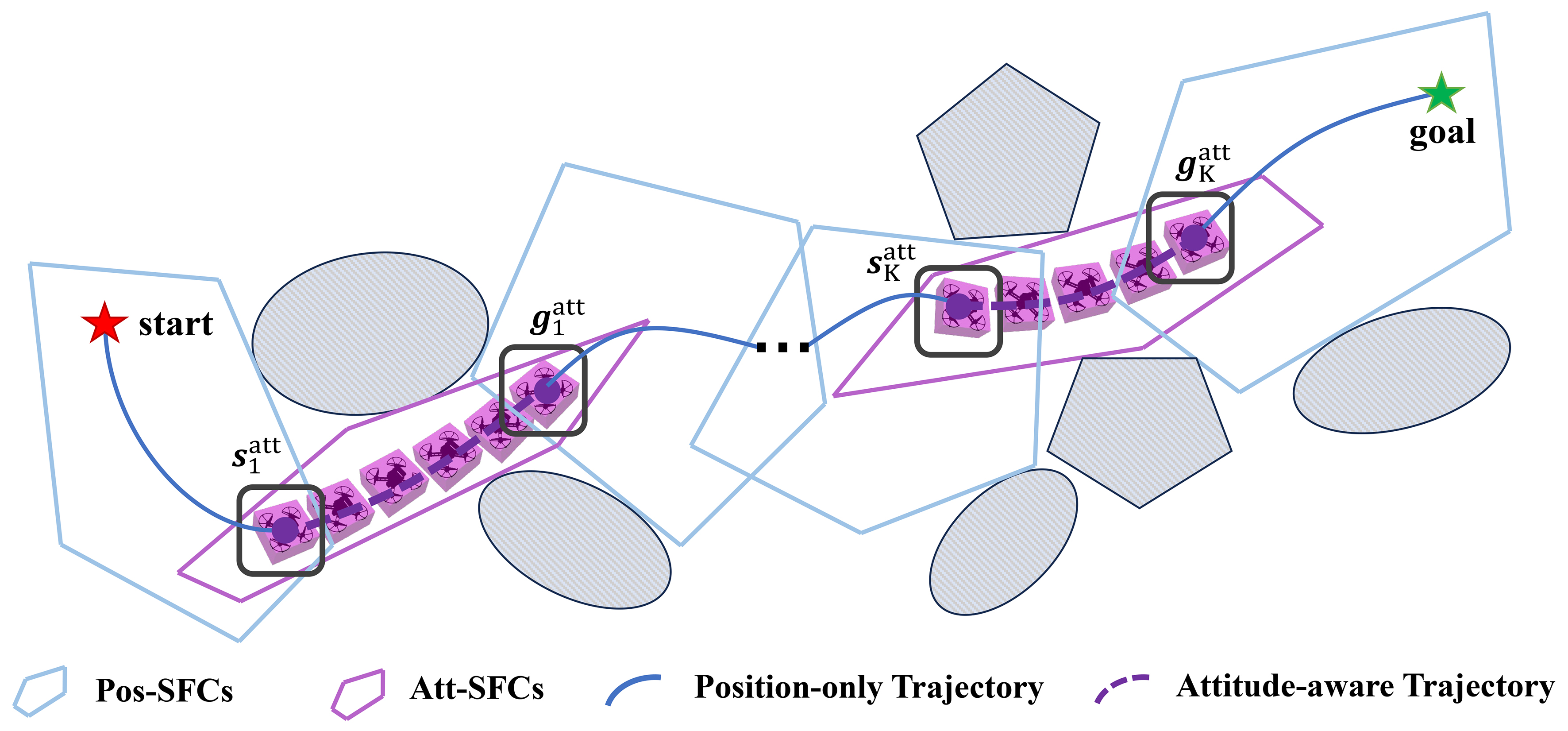
Figure 4. Illustration of the hierarchical whole-body motion-planning mechanism. The blue convex polyhedron denotes a Pos-SFC, in which position-only collision checking is performed. The purple convex polyhedron denotes an Att-SFC, in which attitude-aware collision checking is performed. SFC: Safe flight corridor.
3.2.3. Trajectory refinement
The acceleration-controlled search explicitly determines the duration of each motion primitive, thereby providing a natural initial time allocation for subsequent trajectory refinement. The durations of the searched trajectory segments are collected as
where τ denotes the sampling duration of each motion primitive and topt is the duration of the terminal shot trajectory obtained by solving the LQMT problem.
After the hierarchical search, the resulting trajectory is divided into attitude-aware and position-only segments. Let
For each k ∈
Although acceleration-controlled search substantially improves computational efficiency, directly concatenating the searched motion primitives generally leads to acceleration discontinuities and, consequently, abrupt attitude changes. To improve trajectory continuity without compromising the verified safety of the attitude-aware segments, the proposed refinement strategy keeps all attitude-aware segments fixed and optimizes only the position-only connecting segments. Accordingly, each attitude-aware segment satisfies
The position-only segments are refined by solving the following minimum-jerk problem:
Here,
The constraints in Equations (25c) and (25d) match the boundary states of each position-only segment to those of the adjacent attitude-aware segment. Specifically, the terminal state of each incoming position-only segment is matched to the initial state of the succeeding attitude-aware segment, while the initial state of each outgoing position-only segment is matched to the terminal state of the preceding attitude-aware segment. The constraint in Equation (25e) imposes position, velocity, and acceleration continuity between adjacent position-only segments. Therefore, C2 continuity is enforced at every junction involving an optimized position-only segment.
4. WHOLE-BODY TRAJECTORY TRACKING WITH A DF-MPC
As discussed in[5], although trajectory refinement improves the smoothness of the searched trajectory, the refined reference may still violate the dynamic limits of the quadrotor. To track the desired whole-body trajectory while satisfying the prescribed state and control constraints, we employ a DF-MPC. The controller simultaneously reduces position and attitude-related tracking errors by tracking the desired position, velocity, and acceleration over a finite prediction horizon. Because the attitude is algebraically related to the translational acceleration through the differential-flatness mapping, acceleration tracking contributes directly to attitude tracking. The body angular velocity ω is related to the jerk j. Therefore, a third-order integrator with jerk input is adopted as the prediction model. The state and control input are defined as
Let Δt denote the control interval. Under the zero-order-hold assumption for the jerk input, the discrete prediction model is given by
where
At each control step, DF-MPC predicts the system evolution over N steps and computes the optimal jerk sequence by minimizing a finite-horizon cost function. For trajectory tracking, the objective penalizes both the state-tracking error and the control effort:
where
To obtain the low-level collective-thrust and body-angular-velocity commands, the optimized flat-output quantities are mapped to the physical control inputs. Define the desired mass-normalized collective thrust as
The corresponding collective thrust is fd = mcd, where m is the mass of the quadrotor. The desired body angular velocity is obtained as
Here, R =[xb, yb, zb] is recovered using the differential-flatness mapping introduced in Section 2.1. The mapping assumes cd > 0 and ||yc × zb||2 > 0, thereby excluding zero-thrust and attitude-reconstruction singularities. By minimizing the predicted state error, DF-MPC tracks the desired position through p and the desired attitude indirectly through a. Meanwhile, the jerk input determines the desired body angular velocity through Equation (33).
5. EXPERIMENTS
5.1. Numerical simulation
5.1.1. Ablation studies and parameter selection
We first conducted an ablation study to evaluate the contribution of the trajectory-refinement module. We then examined the effects of the main parameters involved in the motion-primitive search and selected their values through comparative experiments in narrow-passage scenarios.
Effect of trajectory refinement: We compared two configurations: (1) Search only, in which the trajectory generated by the acceleration-controlled whole-body search was used directly without subsequent refinement; and (2) Search + refinement, in which the attitude-aware segments were retained, while the position-only segments were refined using the formulation introduced in Section 3.2.3. Each searched motion primitive applies a constant acceleration input over its duration. Although consecutive primitives are connected in position and velocity, their acceleration inputs are not necessarily identical at the junctions. Because the desired roll and pitch angles are recovered from the desired acceleration through differential flatness, these discontinuities can produce abrupt changes in the desired attitude. As shown in Figure 5A, without refinement, such abrupt acceleration-induced attitude changes can be observed at several primitive junctions. The refinement stage improves the higher-order continuity of the position-only portions while preserving the attitude-aware segments. The resulting trajectory therefore provides smoother attitude transitions while traversing narrow passages. As illustrated in Figure 5B, the refined position-only portions exhibit smoother attitude transitions.
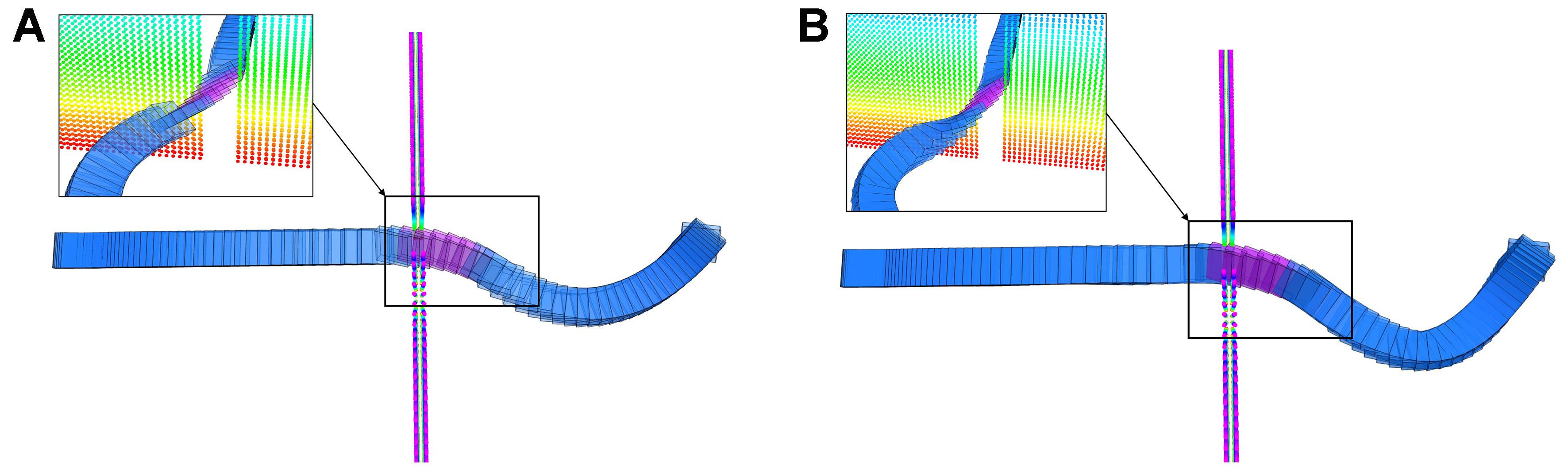
Figure 5. Comparison of the searched and refined trajectories. The purple trajectory denotes the attitude-aware trajectory, while the blue trajectory denotes the position-only trajectory. (A) Acceleration-controlled trajectory without refinement. Abrupt attitude changes occur at the junctions between the two trajectory types; (B) Refined trajectory with smoother transitions. Continuous attitude transitions at their junctions.
Parameter selection. The performance of the motion-primitive search is mainly affected by the primitive cost weight ρ, the primitive duration τ, and the control-space sampling parameter r. The parameter ρ balances traversal time and control effort: a small value favors conservative but longer trajectories, whereas a large value favors faster but potentially more aggressive motions. The duration τ determines the spacing of the state lattice; a small τ increases search resolution and computational cost, while a large τ may produce a lattice that is too sparse to represent feasible transitions near narrow passages. Similarly, increasing r provides a finer control discretization but increases the branching factor as (2r + 1)3, whereas a small r may omit the control inputs required for feasible attitude transitions. Based on comparative experiments in narrow-passage scenarios, we selected ρ = 4umax2, τ = 0.2 s, and r = 2, where umax denotes the maximum control magnitude along each axis. This setting samples five control inputs per axis and generates 125 candidate motion primitives in the three-dimensional control space, providing a practical compromise among trajectory aggressiveness, state-space coverage, and computational efficiency.
5.1.2. Performance evaluation in narrow-passage scenarios
To evaluate the capability of the proposed planner in geometrically constrained environments, we conducted two groups of narrow-passage experiments. The first group evaluates passages with different widths, whereas the second group evaluates rectangular windows with different orientations. In all experiments, the start and goal states were placed on opposite sides of the obstacle, while the dynamic limits and search parameters were kept unchanged.
Passages with different widths: The quadrotor radius was set to 0.35 m, corresponding to a horizontal span of 0.70 m. As shown in Figure 6, the 0.80 m gap is wider than the quadrotor and can therefore be traversed using a position-only trajectory without triggering attitude-aware planning. In contrast, the 0.65 and 0.50 m gaps are narrower than the horizontal span of the quadrotor, requiring progressively larger attitude adjustments to reduce its projected body extent. The results demonstrate that the planner activates attitude-aware motion only when required by the available passage size.

Figure 6. Hierarchical planning results through wall gaps of different widths. (A) 0.80 m gap, where the gap width is larger than the quadrotor’s horizontal span and only position planning is required; (B) 0.65 m gap and (C) 0.50 m gap, where attitude-aware planning is activated.
Windows with different orientations: We further evaluated the planner using a narrow rectangular window with fixed dimensions and orientations of 35°, 45°, and 55°. As shown in Figure 7, the planner generates attitude-aware motions that align the projected body shape with the available free space, with larger window inclinations requiring larger roll adjustments.
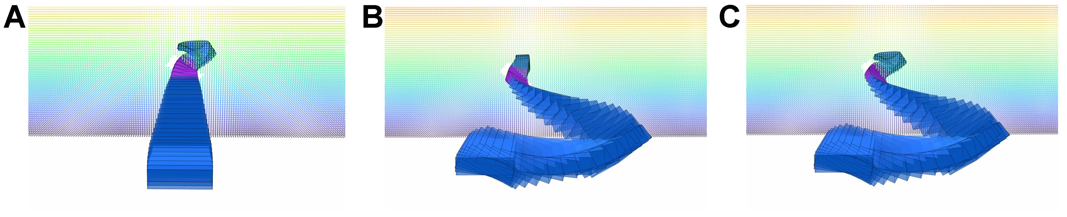
Figure 7. Attitude-aware trajectories through rectangular windows with different orientations. (A) 35°; (B) 45°; (C) 55°.
5.2. Benchmark for whole-body motion planning
In this section, we compare the proposed method with a search-based method[17], denoted as Base-A, and an optimization-based method, denoted as Base-B. Base-B was evaluated using the publicly available CPU implementation released with Fast-Racing[10]. Fast-Racing and the method of Yang et al.[20] share the GCOPTER-based polynomial optimization framework[6] and employ closely related whole-body collision constraints. We therefore used Fast-Racing as the open-source implementation for evaluating Base-B. We test the efficiency and quality of trajectories generated by the proposed method in two different simulated environments: (1) Random forest: 40 m × 20 m × 3 m map containing 150 random obstacles. (2) Office: 60 m × 45 m × 3 m indoor map. All methods accept the same point cloud and goal state inputs, the radius lr =
Our method generates SFC through Jump Point Search (JPS) paths and accelerates the generation of collision-free trajectories through hierarchical planning in Section 3.2. Since search-based methods are sensitive to temporal resolution, we first compare our method with Base-A, and the overall comparison is shown in Figure 8.
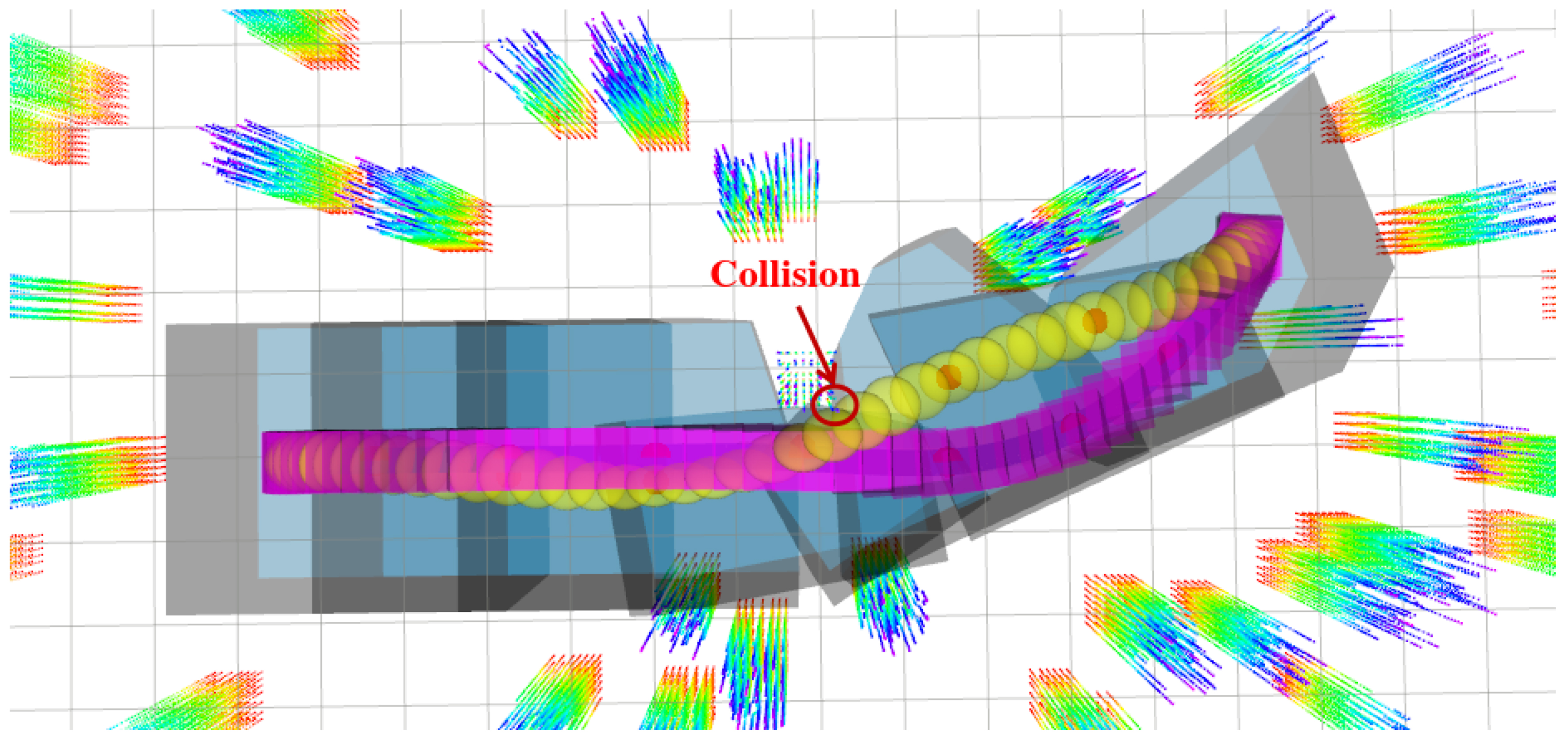
Figure 8. Comparison of the trajectories generated by two search-based methods. The yellow trajectory represents the Base-A, where the trajectory may be too close to the obstacle and may collide when the collision detection resolution is large. The purple trajectory represents our proposed method, which is insensitive to the collision detection resolution.
The results of the benchmark are shown in Table 1. For quantitative comparison, the control cost reported in Tables 1 and 2 is evaluated as f = ∫0T||j(t)||22dt, where j(t) = p(3)(t) denotes the jerk. The bold represents better performance for each individual metric, that is, shorter calculation time and trajectory execution time, less control cost and node usage. For the Base-A method, high-maneuverability trajectories can be generated quickly when the resolution is large, but due to the large time penalty coefficient ρ, the trajectory is too close to the obstacle and may collide. For our method, trajectories with lower control cost can be generated with shorter computation time and fewer node expansions under different resolutions.
Comparison of search-based methods
| tc(s) | te(s) | f(103 × m2/s5) | Node usage | |
| Base-A (res = 0.02 s) | 0.172 | 3.07 | 8.13 | 242 |
| Ours (res = 0.02 s) | 0.031 | 3.16 | 7.09 | 97 |
| Base-A (res = 0.05 s) | 0.166 | 3.02 | 7.97 | 206 |
| Ours (res = 0.05 s) | 0.019 | 3.16 | 6.71 | 97 |
Comparison of trajectories generated by three methods
| Random forest | Office | |||||
| tc(s) | te(s) | f(103 × m2/s5) | tc(s) | te(s) | f(103 × m2/s5) | |
| Base-A | 0.916 | 3.44 | 9.84 | 1.923 | 5.27 | 10.13 |
| Base-B | 0.195 | 4.29 | 8.54 | 0.498 | 6.04 | 8.92 |
| Ours | 0.138 | 4.24 | 8.66 | 0.455 | 5.91 | 9.36 |
To test the quality of our generated trajectories, we compared our method with the optimization-based method (Base-B). Figure 9 shows the comparative experiments of the three methods in two different scenarios. Our method generates trajectories of similar quality to the optimization-based method by restricting the trajectory search space to SFC. At the same time, through the hierarchical planning framework, our method greatly reduces the computation time of the search-based method while ensuring security. The specific results are given in Table 2.
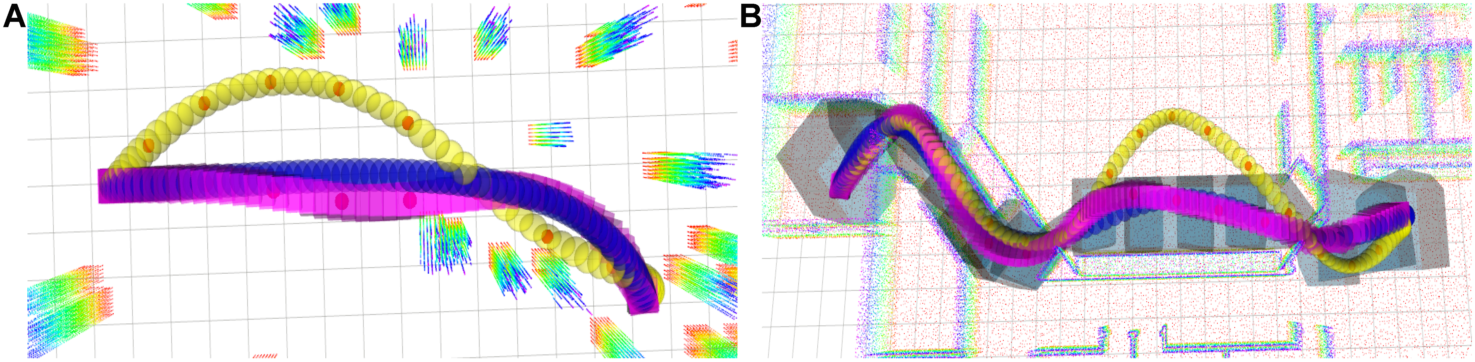
Figure 9. Comparison of the trajectories generated by three methods in two different environments. (A) Trajectories generated by three methods in random forest; (B) Trajectories generated by three methods in Office. The yellow trajectory represents the search-based method (Base-A), the blue trajectory represents the optimization-based method (Base-B), and the purple trajectory represents our proposed method. It can be seen that our method generates trajectories of comparable quality to the optimization-based method and reduces the trajectory calculation time of the search-based method to the millisecond level.
5.3. Controller performance under aggressive flight
High-fidelity quadrotor simulator AirSim[26] is used to verify the tracking performance of the controller under aggressive trajectories. The simulation scene size is 20 m × 70 m × 5 m. The initial position of the quadrotor is (0, 0, 1), the target position is (0, 66, 1), and the reference trajectory duration is set to 11 s to generate an aggressive trajectory. The reference trajectory has a maximum velocity of vy = 9.3 m/s in the y direction and a maximum acceleration of ax = 9.5 m/s2 in the x direction, which are close to the physical limits of actual quadrotors. The DF-MPC problem in Equation (31) is solved using OSQP[27]. The average solution time remained below 1 ms, satisfying the real-time requirement.
As shown in Figure 10, the scene depicts a quadrotor tracking a very challenging reference trajectory in AirSim. The trajectory is extremely aggressive and is characterized by its significant roll and yaw angle changes. Additional simulation results and visualizations are provided in the Supplementary Video.
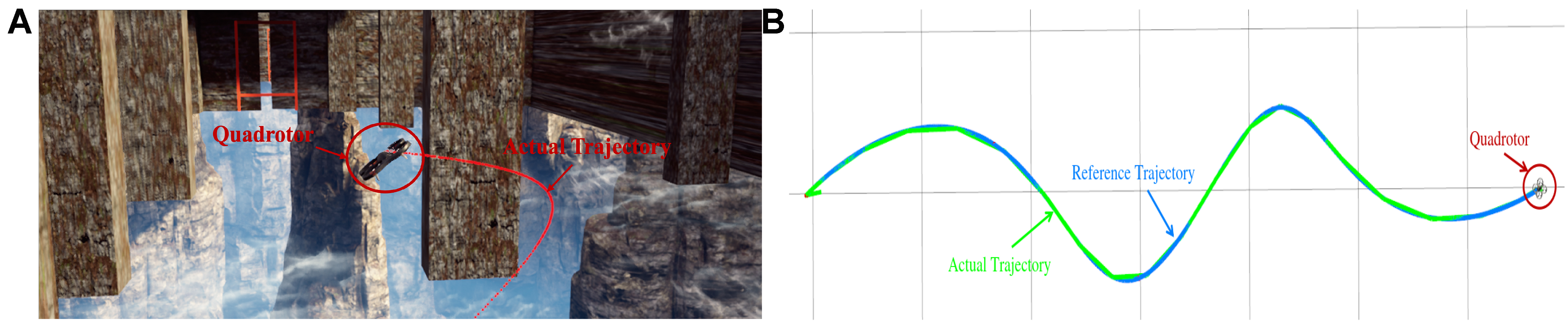
Figure 10. Illustration of a quadrotor tracking an aggressive trajectory in AirSim. (A) AirSim[26] simulation snapshot of the quadrotor flying in an unknown environment; (B) Trajectory tracking performance. The blue curve denotes the reference trajectory, and the green curve denotes the actual trajectory.
For the proposed controller, the discrete time Δt = 0.15 s and the prediction horizon N = 16. The tracking performance of the proposed controller is verified by comparing the position, velocity, and acceleration tracking effects of the quadrotor. Figure 11 shows an illustration of the overall tracking effect, where the blue dashed line represents the reference trajectory and the orange line represents the actual trajectory obtained by the simulator. Our method achieves a position closed loop by tracking the position, and since the acceleration of the quadrotor is directly related to the attitude, the attitude closed loop is achieved by tracking the acceleration.
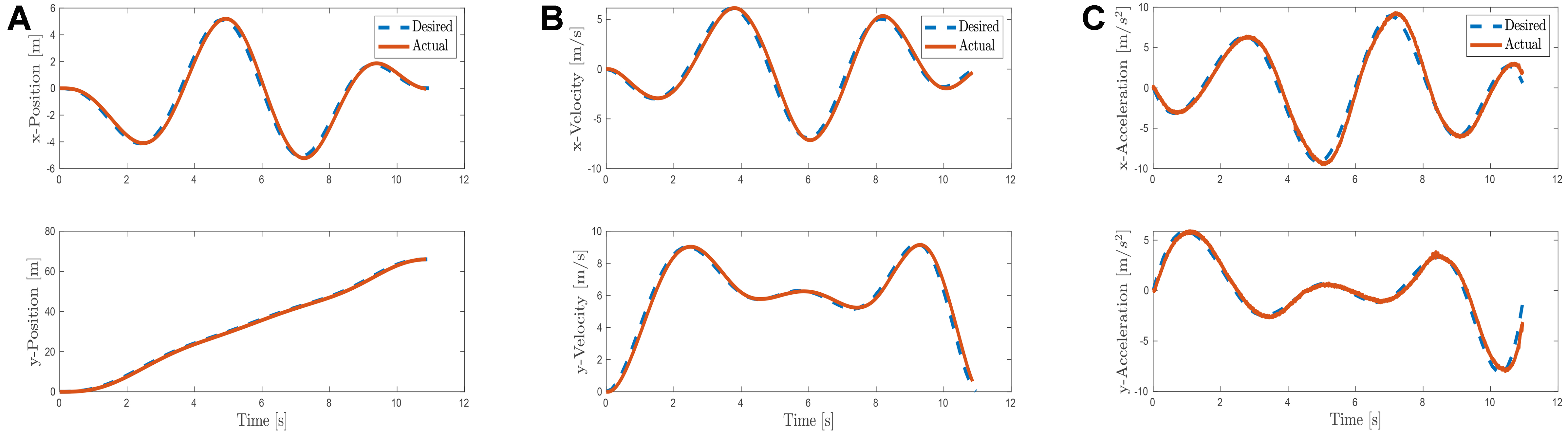
Figure 11. Illustration of the controller’s trajectory tracking performance. (A) shows the position tracking performance; (B) shows the velocity tracking performance; and (C) shows the acceleration tracking performance (reflecting the attitude tracking performance).
6. CONCLUSIONS
In this paper, we propose a search-based hierarchical whole-body motion-planning framework for quadrotors in unknown environments, which improves computational efficiency by approximately 4-9 times compared with the existing search-based whole-body planning method. We first divide the free space into spacious and narrow regions according to the spatial scale characteristics of SFCs in different regions. By utilizing a specially designed hierarchical collision detection algorithm, the original motion planning problem is decomposed into position-only planning and attitude-aware planning, which significantly improves the planning efficiency. Finally, a model predictive controller based on differential flatness is designed, and a high-fidelity simulator is used to test the tracking performance of the controller under aggressive trajectories.
DECLARATIONS
Authors’ contributions
Made substantial contributions to the research, idea generation, algorithm design, and simulation, wrote and edited the original draft: Cui, P.
Performed critical review, commentary, and revision, as well as provided administrative, technical, and material support: Zhang, H.; Du, Z.; Huang, C.; Sun, J.
Availability of data and materials
The data that support the findings of this study are available from the corresponding author upon reasonable request.
AI and AI-assisted tools statement
Not applicable.
Financial support and sponsorship
This work was supported in part by the National Natural Science Foundation of China (62433014 and 62573324) and in part by the Fundamental Research Funds for the Central Universities (22120230311).
Conflicts of interest
Zhang, H. is a Section Chief Editor of the journal Intelligence & Robotics and the Guest Editor of the special topic “Low-Altitude Control and Intelligence”. Zhang, H. was not involved in any steps of the editorial processing, notably including reviewer selection, manuscript handling, or decision-making. The other authors declare that there are no conflicts of interest.
Ethical approval and consent to participate
Not applicable.
Consent for publication
Not applicable.
Copyright
© The Author(s) 2026.
Supplementary Materials
REFERENCES
1. Mellinger, D.; Kumar, V. Minimum snap trajectory generation and control for quadrotors. In 2011 IEEE International Conference on Robotics and Automation, Shanghai, China. May 09-13, 2011. IEEE; 2011. pp. 2520-5.
2. Zhou, X.; Wang, Z.; Ye, H.; Xu, C.; Gao, F. EGO-planner: an ESDF-free gradient-based local planner for quadrotors. IEEE. Robot. Autom. Lett. 2021, 6, 478-85.
3. Zhou, B.; Gao, F.; Wang, L.; Liu, C.; Shen, S. Robust and efficient quadrotor trajectory generation for fast autonomous flight. IEEE. Robot. Autom. Lett. 2019, 4, 3529-36.
4. Gao, F.; Wang, L.; Zhou, B.; Zhou, X.; Pan, J.; Shen, S. Teach-repeat-replan: a complete and robust system for aggressive flight in complex environments. IEEE. Trans. Robot. 2020, 36, 1526-45.
5. Liu, S.; Atanasov, N.; Mohta, K.; Kumar, V. Search-based motion planning for quadrotors using linear quadratic minimum time control. In 2017 IEEE/RSJ International Conference on Intelligent Robots and Systems (IROS), Vancouver, Canada. Sep 24-28, 2017. IEEE; 2017. pp. 2872-9.
6. Wang, Z.; Zhou, X.; Xu, C.; Gao, F. Geometrically constrained trajectory optimization for multicopters. IEEE. Trans. Robot. 2022, 38, 3259-78.
7. Deng, W.; Chen, H.; Ye, B.; Chen, H.; Li, Z.; Lyu, X. Whole-body integrated motion planning for aerial manipulators. IEEE. Trans. Robot. 2025, 41, 6661-79.
8. Sun, Y.; Zhu, H.; Liang, Z.; Liu, A.; Ni, H.; Wang, Y. A phase search-enhanced Bi-RRT path planning algorithm for mobile robots. Intell. Robot. 2025, 5, 404-18.
9. Falanga, D.; Mueggler, E.; Faessler, M.; Scaramuzza, D. Aggressive quadrotor flight through narrow gaps with onboard sensing and computing using active vision. In 2017 IEEE International Conference on Robotics and Automation (ICRA), Singapore. May 29 - Jun 03, 2017. IEEE; 2017. pp. 5774-81.
10. Han, Z.; Wang, Z.; Pan, N.; Lin, Y.; Xu, C.; Gao, F. Fast-racing: an open-source strong baseline for SE(3) planning in autonomous drone racing. IEEE. Robot. Autom. Lett. 2021, 6, 8631-8.
11. Cui, P.; Zhang, H.; Du, Z.; Yan, H. PolyMap: a lightweight polyhedral map based on approximate convex decomposition for aerial robot motion planning. IEEE. Robot. Autom. Lett. 2026, 11, 3055-62.
12. Wang, Q.; Wang, Z.; Pei, L.; Xu, C.; Gao, F. A linear and exact algorithm for whole-body collision evaluation via scale optimization. In 2023 IEEE International Conference on Robotics and Automation (ICRA), London, UK. May 29 - Jun 02, 2023. IEEE; 2023. pp. 3621-7.
13. Rao, K.; Yan, H.; Lv, Y.; Wu, Z.; Wu, X.; Zhang, Y. Decentralized pursuit of an evader with probabilistic collision-free for differential drive robots. IEEE. Trans. Cybern. 2026, 56, 4391-402.
14. Liu, S.; Watterson, M.; Mohta, K.; et al. Planning dynamically feasible trajectories for quadrotors using safe flight corridors in 3-D complex environments. IEEE. Robot. Autom. Lett. 2017, 2, 1688-95.
15. Deits, R.; Tedrake, R. Efficient mixed-integer planning for UAVs in cluttered environments. In 2015 IEEE International Conference on Robotics and Automation (ICRA), Seattle, USA. May 26-30, 2015. IEEE; 2015. pp. 42-9.
16. Wang, Q.; Wang, Z.; Wang, M.; et al. Fast iterative region inflation for computing large 2-D/3-D convex regions of obstacle-free space. IEEE. Trans. Robot. 2025, 41, 3223-43.
17. Liu, S.; Mohta, K.; Atanasov, N.; Kumar, V. Search-based motion planning for aggressive flight in SE(3). IEEE. Robot. Autom. Lett. 2018, 3, 2439-46.
18. Wu, T.; Chen, Y.; Chen, T.; Zhao, G.; Gao, F. Whole-body control through narrow gaps from pixels to action. In 2025 IEEE International Conference on Robotics and Automation (ICRA), Atlanta, USA. May 19-23, 2025. IEEE; 2025. pp. 11317-24.
19. Zhang, L.; Hu, Y.; Yu, F.; Deng, Y.; Yu, W.; Zou, D. Vision-based end-to-end learning for UAV traversal of irregular gaps via differentiable simulation. IEEE. Robot. Autom. Lett. 2026, 11, 7748-55.
20. Yang, S.; He, B.; Wang, Z.; Xu, C.; Gao, F. Whole-body real-time motion planning for multicopters. In 2021 IEEE International Conference on Robotics and Automation (ICRA), Xi’an, China. May 30 - Jun 05, 2021. IEEE; 2021. pp. 9197-203.
21. Lee, T.; Leok, M.; McClamroch, N. H. Geometric tracking control of a quadrotor UAV on SE(3). In 49th IEEE Conference on Decision and Control (CDC), Atlanta, USA. Dec 15-17, 2010. IEEE; 2010. pp. 5420-5.
22. Faessler, M.; Falanga, D.; Scaramuzza, D. Thrust mixing, saturation, and body-rate control for accurate aggressive quadrotor flight. IEEE. Robot. Autom. Lett. 2017, 2, 476-82.
23. Faessler, M.; Franchi, A.; Scaramuzza, D. Differential flatness of quadrotor dynamics subject to rotor drag for accurate tracking of high-speed trajectories. IEEE. Robot. Autom. Lett. 2018, 3, 620-6.
24. Peng, Y.; Yan, H.; Rao, K.; Yang, P.; Lv, Y. Distributed model predictive control for unmanned aerial vehicles and vehicle platoon systems: a review. Intell. Robot. 2024, 4, 293-317.
25. Verriest, E. I.; Lewis, F. L. On the linear quadratic minimum-time problem. IEEE. Trans. Autom. Control. 1991, 36, 859-63.
26. Shah, S.; Dey, D.; Lovett, C.; Kapoor, A. AirSim: high-fidelity visual and physical simulation for autonomous vehicles. arXiv 2017, arXiv:1705.05065. Available online: https://doi.org/10.48550/arXiv.1705.05065. (accessed on 13 Aug 2026).
Cite This Article
 Open Access
How to Cite
Download Citation
Export Citation File:
Type of Import
Tips on Downloading Citation
Citation Manager File Format
Type of Import
Direct Import: When the Direct Import option is selected (the default state), a dialogue box will give you the option to Save or Open the downloaded citation data. Choosing Open will either launch your citation manager or give you a choice of applications with which to use the metadata. The Save option saves the file locally for later use.
Indirect Import: When the Indirect Import option is selected, the metadata is displayed and may be copied and pasted as needed.
About This Article
Special Topic
Copyright

Data & Comments
Data
0










Comments
Comments must be written in English. Spam, offensive content, impersonation, and private information will not be permitted. If any comment is reported and identified as inappropriate content by OAE staff, the comment will be removed without notice. If you have any queries or need any help, please contact us at [email protected].