


A soft closed-loop glove with gesture sensing and haptic feedback for real-time human-machine interfaces
 0
0 Abstract
Human-machine interfaces (HMIs) are essential tools facilitating effective interactions between users and intelligent systems. However, current wearable HMIs, particularly smart gloves, often face challenges in precisely recognizing subtle finger movements and delivering real-time tactile feedback, limiting their operational effectiveness and user immersion. To overcome these challenges, we propose an intelligent glove system integrating highly stretchable liquid metal-based strain sensors and programmable electromagnetic feedback actuators to realize closed-loop immersive human-machine interaction. The strain sensors achieve superior stretchability (over 200%), linear response, minimal hysteresis, and robust durability, effectively capturing complex hand movements. Gesture recognition, performed by a convolutional neural network, achieves an accuracy of 98% across common gestures, demonstrating exceptional precision and robustness. Furthermore, the glove integrates soft programmable electromagnetic actuators that generate an output force greater than 0.25 N, providing adjustable and precise tactile feedback via pulse-width modulation. This allows users to intuitively perceive tactile sensations in human-machine interaction scenarios, including robotic manipulation and motion guidance tasks. Comprehensive experiments confirm the intelligent glove system’s superior real-time responsiveness and adaptability in dynamic environments. This advanced closed-loop HMI glove significantly enhances operator immersion, operational accuracy, and interaction realism, demonstrating strong potential in robotics, virtual reality, and remote teleoperation applications.
Keywords
INTRODUCTION
Human-machine interfaces (HMIs) are essential tools for facilitating effective, direct, and realistic interactions between users and robotic systems[1,2]. With advancements in technology, HMIs have evolved from traditional, rigid, non-wearable devices (e.g., mice and remote controllers) to wearable, intelligent, and diversified interactive systems, fostering more reliable and authentic human-machine interactions[3,4]. Among these, wearable smart gloves have emerged as a pivotal HMI technology, addressing the limitations of traditional sensors in complex environments, such as limited degrees of freedom in joysticks[2], two-dimensional constraints in touchscreens, and occlusion issues in camera-based tracking. These gloves capture motion data, including real-time tracking of finger bending angles, enabling natural human-machine communication. This capability holds great promise for applications in robotics and virtual reality[5]. For instance, in hazardous environments, wearable gloves can translate hand movements into robotic commands, allowing robots to perform complex assembly or repair tasks. Similarly, they play a crucial role in virtual surgical training and telemedicine, enabling physicians to interact with virtual environments for training or therapeutic purposes[6].
Despite these advantages, wearable smart gloves face challenges in accurately recognizing fine and complex movements of fingers and providing precise tactile feedback for operators in real time[7]. Sensor arrays in these gloves typically rely on three main sensing principles: inertial sensing using inertial measurement units (IMUs), triboelectric sensing, and resistive strain sensing with flexible materials[8,9]. A detailed comparison is provided in Supplementary Tables 1 and 2. Fan et al. developed a smart glove with an IMU for real-time hand-motion tracking, enabling precise dynamic gesture recognition by exploiting the IMU’s ability to provide absolute position and motion data[10]. However, IMU-based gloves rely on rigid components, which can cause discomfort during prolonged use, and accumulated measurement errors reduce their ability to precisely track subtle finger movements[11-13]. Wen et al. proposed a triboelectric nanogenerator (TENG)-based smart glove for sign language recognition[14]. Gloves based on the triboelectric principle offer excellent dynamic responsiveness. However, TENGs are intrinsically limited to dynamic gestures and cannot accurately capture static finger positions[15-17]. Lee et al. built a heterogeneous omnidirectional strain-sensor array with triangular elements[18]. These resistive strain sensors offer good flexibility, ease of integration, and high sensitivity, making them widely applicable. However, conventional designs often exhibit limited stretchability and inadequate stability under prolonged dynamic conditions[19-22]. Therefore, developing wearable sensors that can simultaneously meet the demanding requirements of stability, flexibility, and sensitivity for precise motion capture remains a key challenge in advancing smart glove technology.
In addition to motion capture, providing operators both comfort and real-time tactile feedback is a major focus of HMI research[23,24]. As specifically compared in Supplementary Table 3, Yamaguchi et al. present a handshake glove based on a pneumatic/hydraulic system capable of delivering high output force[25]. However, such gloves suffer from slow response and require bulky external equipment[26-28]. These actuators often feature rigid structures, compromising comfort and usability during prolonged wear and leading to fatigue or discomfort. In contrast, Zhu et al. proposed a piezoelectrically driven haptic glove using lead zirconate titanate (PZT) vibrotactile actuators driven near 270 Hz resonance with 6-12 V input, enabling adjustable multi-channel haptic feedback[2]; however, their limited output force and small deformation range make them inadequate for haptic feedback applications[29,30]. In response to these limitations, Gu et al. show that dielectric elastomer actuators (DEAs) achieve > 100% strain with millisecond response at 100 V/µm using a typical stress of 100 kPa, a single-layer, centimeter-scale device yields N to tens-of-newtons blocking force[31]. However, such DEAs require high driving voltages, creating operational challenges and potential safety risks that limit their practical use[31,32]. In contrast, electromagnetic actuators offer suitability for real-time feedback due to their fast response and appropriate output force[33-38].
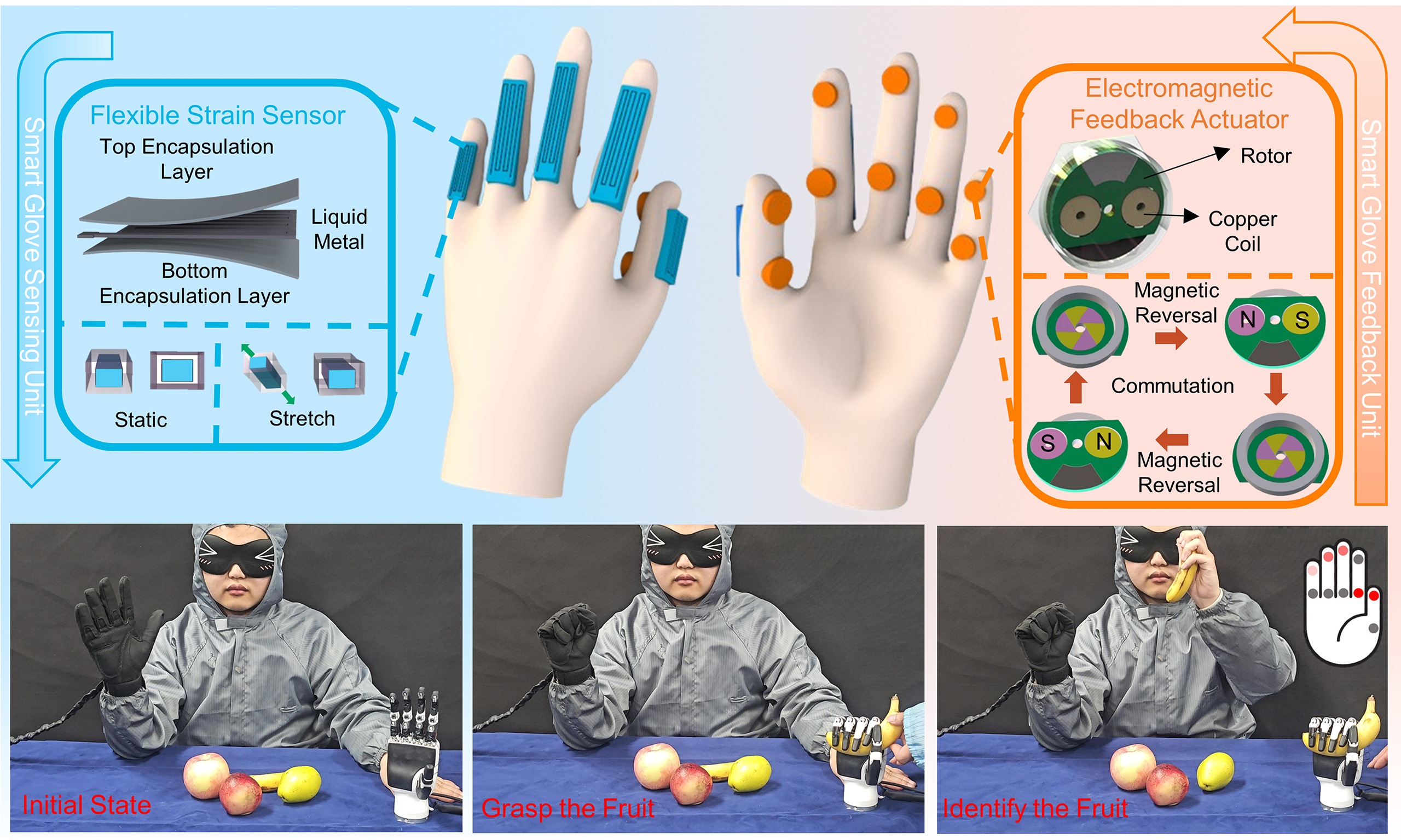
To overcome these challenges and enhance wearable HMI performance, we developed a soft, closed-loop human-machine interaction glove [Figure 1A] that augments operator immersion through precise gesture sensing and realistic tactile feedback. The system integrates liquid-metal strain sensors and programmable soft electromagnetic feedback actuators as core components. Five strain sensors are positioned on the dorsal finger joints to capture gestures with high fidelity, while ten feedback actuators are arranged on the palmar side at the fingertips and interphalangeal joints to deliver diverse tactile cues. As shown in Figure 1B(i), each sensor adopts a liquid-metal “sandwich” structure - top and bottom encapsulation layers enclosing a liquid-metal conductor - providing high stability, large stretchability, and excellent wearing comfort for long-duration, accurate tracking of dynamic gestures. The sensing unit consists of an Ecoflex flexible substrate with functional liquid-metal electrodes patterned in a grid. When external strain is applied, the Ecoflex stretches and the grid-patterned liquid-metal traces elongate (with a reduction in cross-section), which increases their electrical resistance according to Ohm’s law. The resulting monotonic relative resistance change (ΔR/R0)–strain relationship allows precise strain quantification for robust gesture tracking. Here, ΔR is the change in resistance, and R0 is the initial resistance. The soft electromagnetic feedback actuator [Figure 1B(ii)] generates vibrations by driving a rotor with two coils in a constant magnetic field. Its compact, energy-efficient, and flexible design provides high output and programmability while greatly improving comfort and integration compared with conventional rigid, bulky electromagnetic actuators.
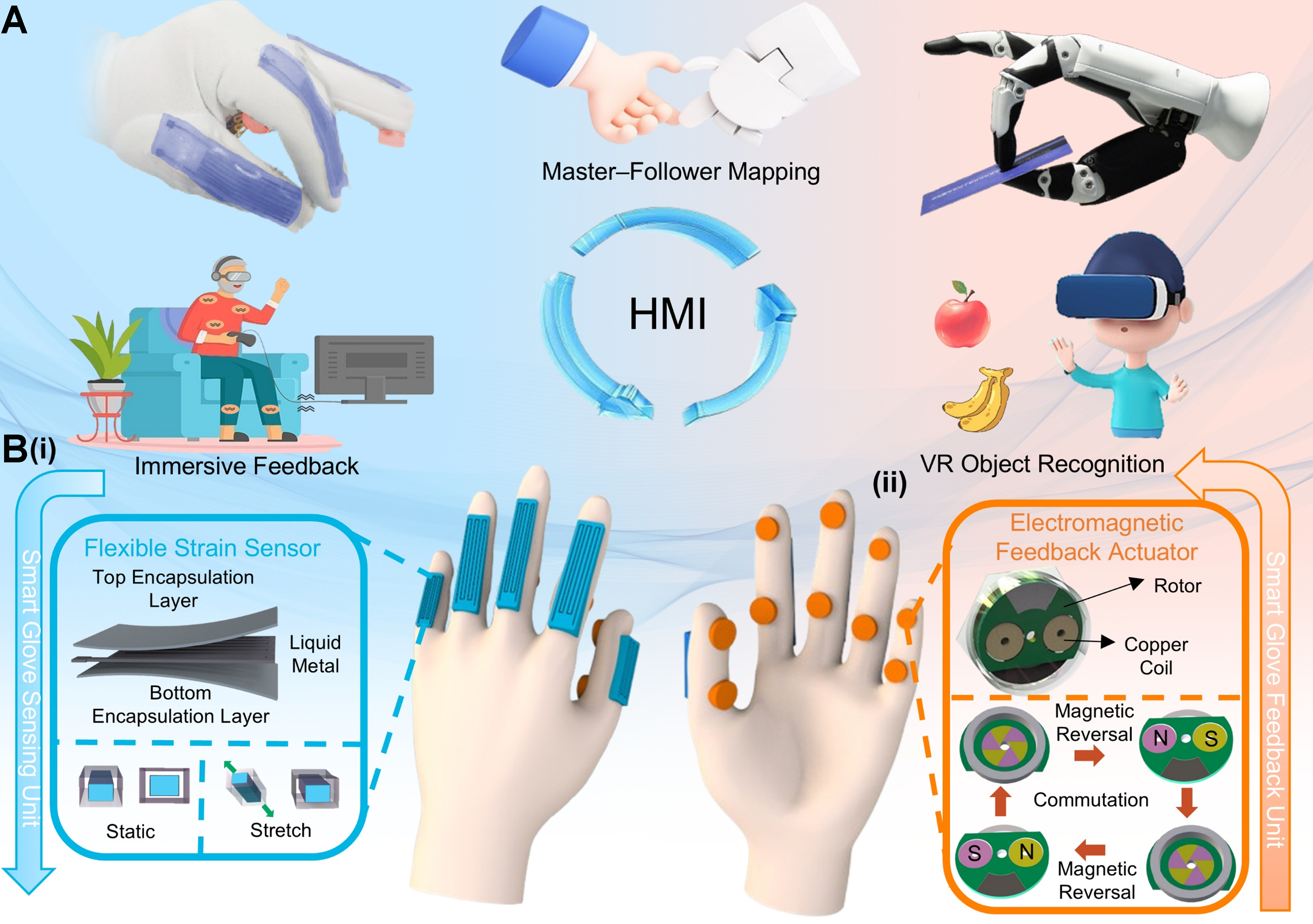
Figure 1. Schematic of the intelligent glove system. (A) Overview of the soft closed-loop wearable glove system; [B(i)] Structural design of the liquid metal strain sensor; [B(ii)] Operating principle of the electromagnetic feedback actuator (Some image elements were either photographed by the authors or obtained from open-source websites: Pixabay and FreeImages). HMI: Human-machine interface; VR: virtual reality.
We systematically characterized the strain sensors for sensitivity, hysteresis, and stability, as well as the tactile feedback actuator for output force and reconfigurability. With sensors on the back of the glove and actuators on the palmar side, the glove enabled accurate gesture capture and motion recognition, supporting precise master-follower control of a robotic hand and providing tactile feedback from the robot to the operator, thereby enhancing immersion. The programmable feedback further supported tasks such as navigation and motion guidance for users with limited vision[34]. These results highlight the glove as a versatile and reliable HMI platform for applications in robotics, virtual and augmented reality (VR/AR), and beyond.
EXPERIMENTAL
Fabrication of flexible liquid-metal strain sensors
The flexible substrate of the sensor was fabricated using Ecoflex (Smooth-On, Inc., USA). Components A and B (Part A: base; Part B: curing agent) were mixed at a 1:1 volume ratio and degassed in vacuum for five minutes to remove air bubbles. The mixture was evenly poured into a metal mold featuring a 600-μm-deep groove and cured at 60 °C for 20 min, forming both top and bottom encapsulation layers. The sensing layer of the liquid metal-based strain sensor was prepared by blending Gallium-Indium-Tin alloy (Galinstan, Sigma-Aldrich, USA) with high-purity iron powder (99.9%, Alfa Aesar, USA) at a 2:1 mass ratio. The iron powder consisted of uniform metallic particles (approximately 100-200 µm), fine enough to achieve homogeneous dispersion in the liquid metal but large enough to prevent oxidation and agglomeration. Manual premixing followed by mechanical stirring at 1,000 rpm for 30 min resulted in a stable silver-colored liquid metal mixture, which was used to form the strain-sensing element.
Fabrication of the minimal feedback actuator unit
The bottom flexible printed circuit board (FPCB) and the rotor bottom printed circuit board (PCB) were fabricated by JLC Technology Group, China. The electrical brushes and supporting columns were produced by precision machining to ensure dimensional accuracy and assembly consistency. The rotor body was manufactured by 3D printing, and the coil was soldered to the bottom PCB through pre-designed slots to complete the electrical connection. The upper flexible cap was fabricated using the same molding and curing procedure as that employed for the strain sensor substrate and was subsequently assembled with the lower structural components to form an integrated device.
Modular integration method for feedback actuators
The system adopts a modular architecture consisting of a central trunk and multiple branch modules. The hexagonal trunk provides six identical plug-and-play electromechanical ports that distribute power and a shared control bus. Each branch is individually addressable, enabling software-programmable activation and feedback. Modules can be added, removed, or rearranged without redesign, allowing rapid reconfiguration into arbitrary layouts.
RESULTS AND DISCUSSION
Design and characterization of the strain sensor
Figure 2A illustrates the straightforward and efficient fabrication process of the flexible strain sensor. First, the Ecoflex prepolymer is injected into a mold to form the bottom encapsulation layer, which is then cured to create a flexible substrate. Next, a strain-gauge stencil is placed on the substrate, and the functional liquid metal is uniformly applied within the stencil openings. After stencil removal, lead wires are attached to both ends of the liquid metal electrodes. Finally, the sensor is encapsulated by overlaying another layer of Ecoflex prepolymer, followed by curing to complete the device.
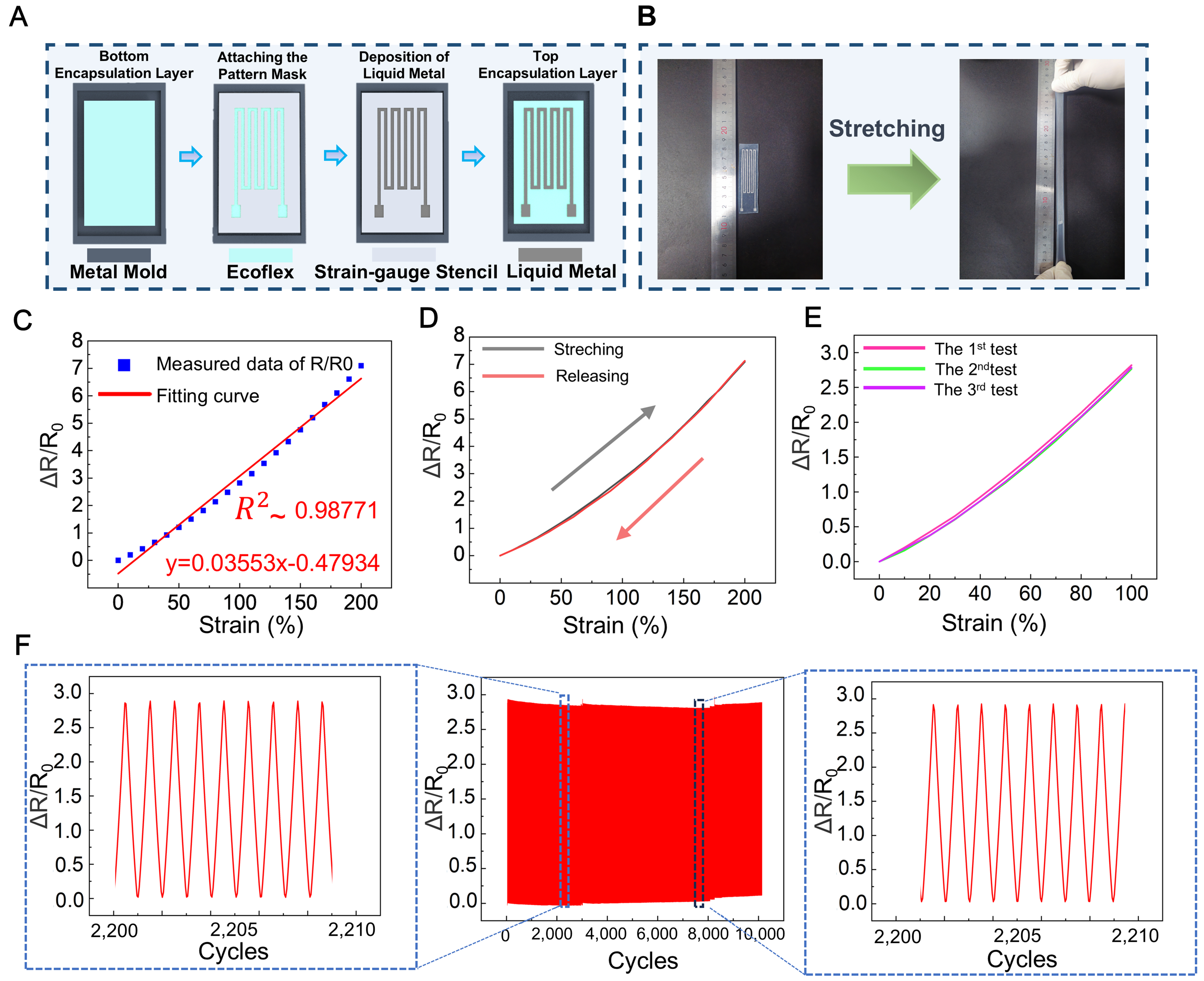
Figure 2. Fabrication and characterization of the flexible strain sensor. (A) Fabrication process of the flexible strain sensor; (B) Tensile stretching demonstration of the sensor; (C) Relative resistance change during 0%-200% sensor stretching; (D) Hysteresis of the strain sensor; (E) Repeatability of the strain sensor under 100% tensile strain; (F) Cyclic tensile test for 10,000 cycles at 100% strain.
To systematically characterize the mechanical and electrical properties of the sensor, tensile tests were conducted using the setup shown in Supplementary Figure 1A. The sensor demonstrates elongation exceeding 200% [Figure 2B], confirming its exceptional stretchability. As shown in Figure 2C, the sensor exhibits high sensitivity and measurement accuracy during strain detection. A highly linear relationship between resistance change and applied strain is observed, which is maintained even at a maximum strain of 200%, highlighting its superior sensing performance. For hysteresis evaluation, the sensor was stretched to 100% strain and then gradually released in 10% intervals. Figure 2D shows that the resistance curves during stretching and release nearly overlap, indicating minimal hysteresis and excellent reversibility, enabling accurate strain measurements under dynamic stretching and recovery conditions. To enable quantitative comparison with prior work, we report the gauge factor (GF) of the sensor, which is defined as
where ΔR is the change in resistance, R0 is the initial resistance, and ε is the applied strain.
Based on a linear fit of ΔR/R0 vs. strain, the sensor exhibits GF ≈ 3.553 within the detection range, indicating high sensitivity to small strains.
Further stability tests validate the sensor’s robust performance under repeated strain. As shown in Figure 2E, three independent tensile experiments produced almost identical resistance-change curves, demonstrating the sensors’ consistent electrical properties. Additionally, durability tests involving 10,000 stretching cycles revealed stable resistance changes [Figure 2F], underscoring the sensor’s mechanical and electrical stability under prolonged dynamic conditions. To further assess the sensor’s stability, a day-to-day cycling test at 100% strain was performed for ten days, as shown in Supplementary Figure 2, demonstrating minor fluctuations with no cumulative drift. These results demonstrate that the liquid-metal-based flexible strain sensor possesses exceptional sensitivity, linear response, minimal hysteresis, high stability and durability. To quantify thermal effects, we measured the strain response at 25-75 °C. As shown in Supplementary Figure 3, the ΔR/R0–strain curves largely overlap across temperatures, indicating minimal temperature dependence, with only slight deviation at the highest temperature. These results demonstrate that the sensor maintains consistent sensitivity and linearity across the tested temperature range.
Gesture/sign language capture and recognition system
To achieve mapping between operator gestures and robotic hand motions, the strain sensors were affixed to the finger joints of the gloves, enabling real-time monitoring of finger bending based on strain [Figure 3A(i)]. As the operator bends a finger, the sensor deforms, and the resulting strain signals are processed by a microcontroller, converting them into electrical signals for precise robotic hand control. Changes in sensor resistance are directly correlated with finger bending. Testing revealed that the sensor can stretch by up to approximately 20% when integrated onto a finger. Calibration data are presented in Supplementary Figure 4. As shown in Figure 3A(ii), the glove system enables accurate mapping of operator hand gestures to robotic hand movements[39]. The real-time performance of gesture mapping is illustrated in Supplementary Video 1, showing minimal delay and stable response during continuous hand movements.
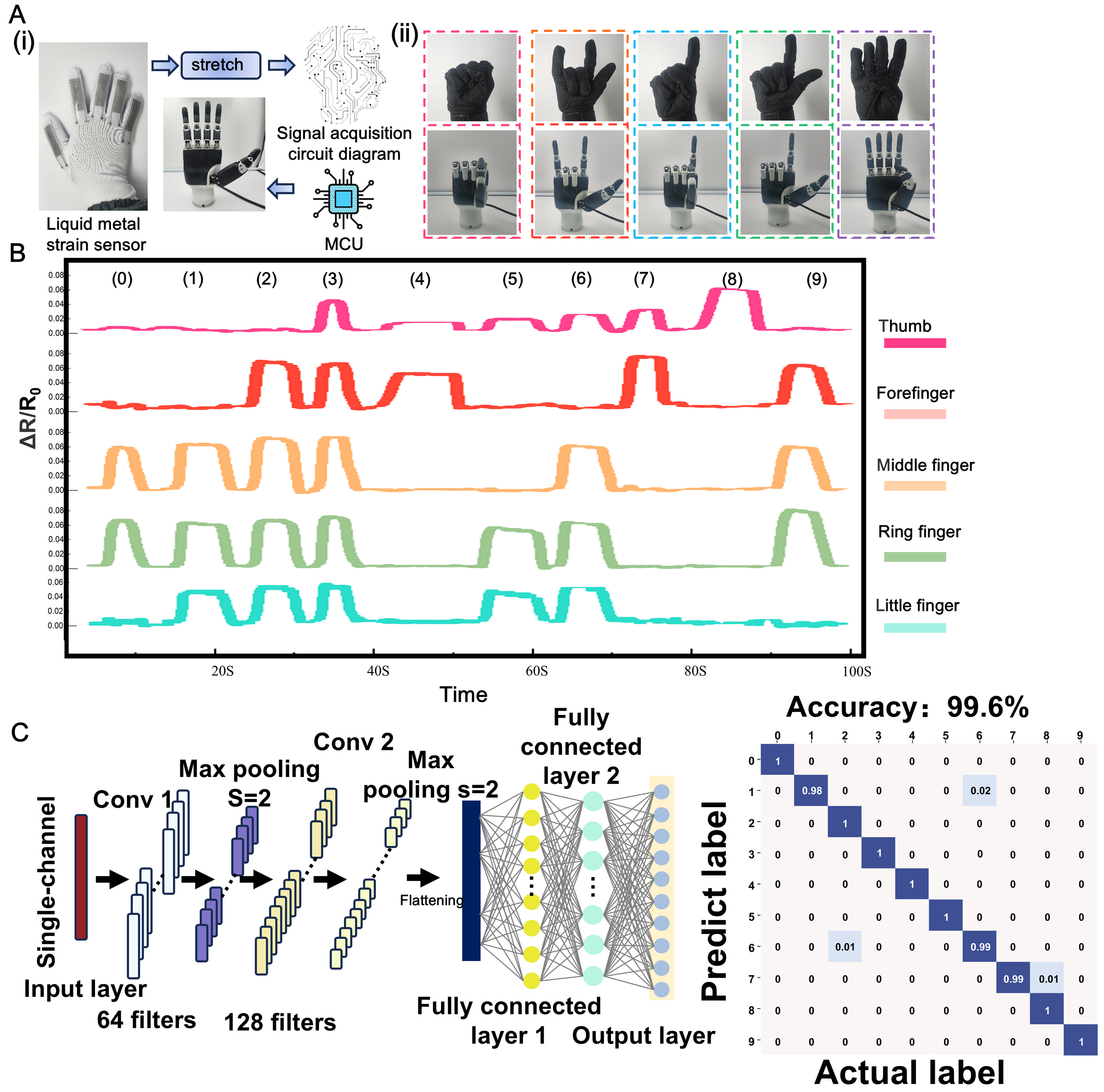
Figure 3. Gesture capture, mapping and recognition system. [A(i)] Schematic of the gesture capture and mapping system; [A(ii)] Demonstration of ten common sign-language gestures; (B) Real-time signals generated by the smart glove for the ten representative gestures; [C(i)] Architecture of the CNN model; [C(ii)] Confusion matrix of the test set. Some image elements are photographs taken by the authors or obtained from open-source websites (Pixabay and FreeImages). CNN: Convolutional neural network; MCU: microcontroller unit.
Figure 3B shows the output signals of the five strain sensors across ten representative gestures (0-9), with detailed definitions and photographs provided in Supplementary Figure 5. The traces are clearly distinguishable, demonstrating the glove’s suitability for gesture recognition. Although simple rule-based thresholds were initially used because the traces appeared clean, small placement shifts and speed variations across wearers and sessions made these rules unreliable. Therefore, a learning-based model was adopted, maintaining stable accuracy without hand-tuned thresholds. Using this approach, we implemented a gesture-recognition system based on the proposed HMI glove for automatic classification of common sign-language gestures. The system processes real-time normalized resistance signals (ΔR/R0) from the glove to capture finger-motion dynamics.
For feature extraction and classification, the system employs a convolutional neural network (CNN) as its core deep learning model [Figure 3C]. The architecture includes two convolutional layers (Conv 1 and Conv 2), each followed by max-pooling operations to reduce data dimensionality and extract key features. The convolutional layers use 64 and 128 filters, respectively, effectively capturing local patterns in the input signals. After feature extraction, the data are flattened and passed to fully connected layers for further processing. Rectified linear unit (ReLU) activation is applied to the fully connected layers during training. The output layer predicts gesture categories by computing class probabilities with a Softmax function. Optimization is performed using Adam (β1 = 0.9, β2 = 0.999) with a weight decay of 1 × 10⁻⁴. The learning rate is set to 0.01 to promote smooth and stable convergence. These settings yield stable and consistent classification performance.
Ten gesture classes were considered. For each volunteer, 500 samples per class were collected (5,000 samples per volunteer in total), and a randomized 80/20 train–test split stratified by class was applied. After 100 epochs, the model achieved 100% training accuracy, indicating convergence; test performance is summarized in Figure 3C. When all test samples from six volunteers (V1-V6) were pooled, the system achieved an average recognition accuracy of 99.6% across the ten classes, demonstrating high effectiveness and precise real-time control of the robotic hand for intuitive human–robot interaction. In addition to the pooled result, cross-subject variability was quantified using subject-specific models for V1-V6. Supplementary Figure 6 presents the corresponding confusion matrices and accuracies, where C denotes per-subject accuracy: C1, 99.7%; C2, 100%; C3, 98.1%; C4, 99.9%; C5, 99.9%; and C6, 100%. Across subjects, the mean ± standard deviation was 99.6% ± 0.74%. Supplementary Figure 7 provides hand-morphology images of V1-V6 for context. To ensure transparency of the training protocol, Supplementary Figures 8-10 present epoch-wise learning curves (training and validation accuracy and loss) for V1-V3, V4-V6, and the pooled dataset, respectively. Validation accuracy increases rapidly and then saturates near the reported level, while validation loss decreases and plateaus. The small gap between training and validation performance indicates stable convergence without evident overfitting under the adopted settings.
Working principle, fabrication, and characterization of the electromagnetic feedback actuator
Subsequently, an electromagnetic feedback actuator is proposed to deliver haptic feedback in the form of vibrations to the operator, thereby enhancing immersion and operational experience. The actuator design, based on a FPCB, is illustrated in Figure 4A. The actuator comprises a flexible cap to enable comfortable user interaction, a rotor embedded with two coils for electromagnetic actuation, and a commutator located at the bottom of the rotor to facilitate electrical conduction; the commutator is divided into six segments. The connection scheme between the two coils and the six commutator pads is shown in Supplementary Figure 11A. Permanent magnets generate a stable magnetic field, while electrical brushes contact the bottom of the commutator to supply a continuous current to the rotor. Three-dimensionally printed supporting columns provide mechanical stability and structural integration, and the bottom FPCB serves as the primary electrical and mechanical platform. In addition, the actuator demonstrates good flexibility and ease of integration, as shown in Figure 4B(i).
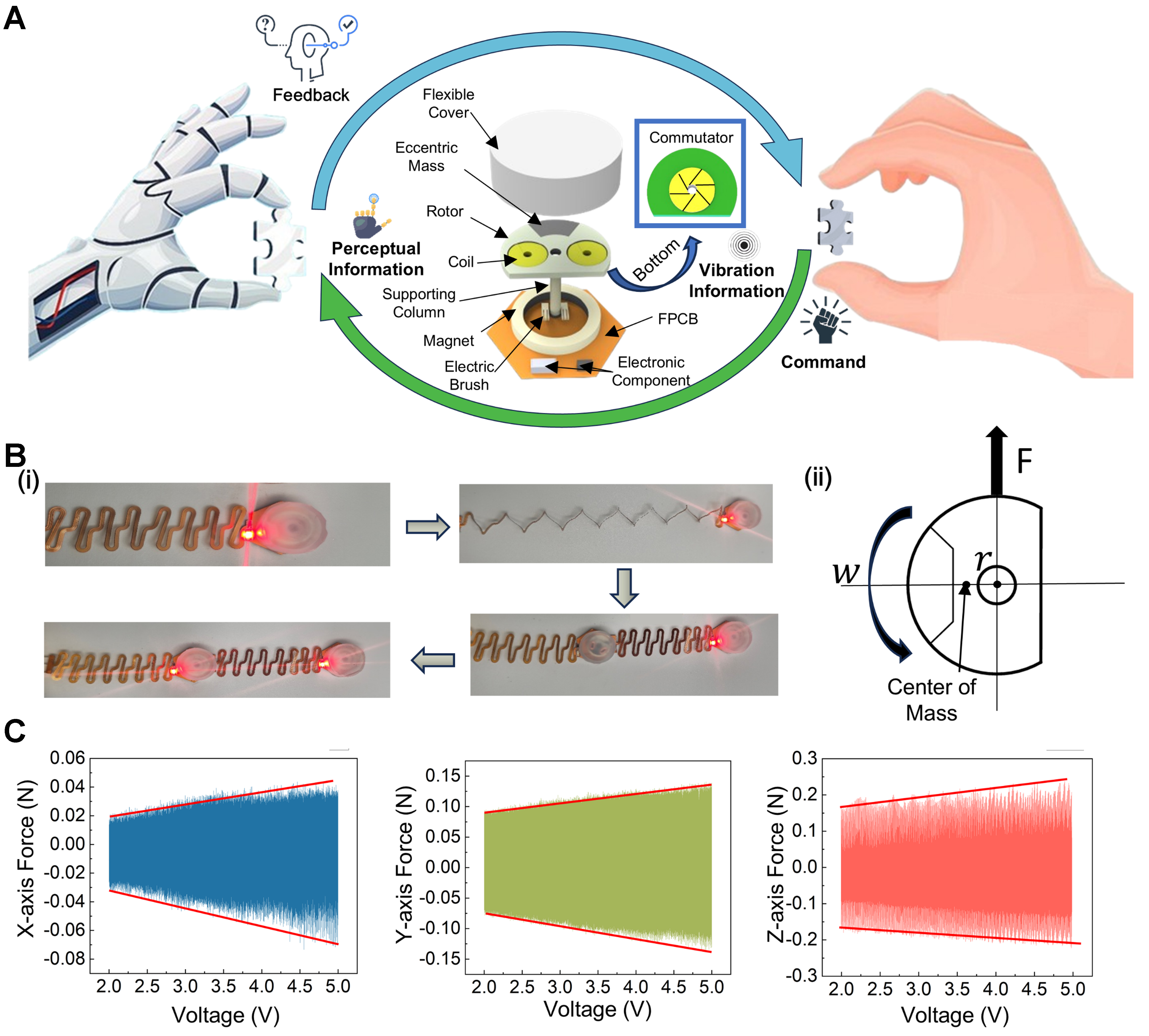
Figure 4. Structure and characterization of the electromagnetic actuator. (A) Exploded view of the electromagnetic actuator; [B(i)] Demonstration of actuator stretchability and modular combination; [B(ii)] Working principle of the actuator; (C) Output of the electromagnetic actuator in the X, Y, and Z directions. (Some image elements are from open-source websites: Pixabay and FreeImages). FPCB: Flexible printed circuit board.
The actuator operates based on Faraday’s law of electromagnetic induction, thereby enhancing the realism and comfort of vibration feedback. When powered, current flows through the FPCB to the compliant electrical brushes. These flexible brushes maintain reliable contact with the segmented commutator at the bottom of the rotor and are electrically connected to the coils, forming a closed-loop circuit and generating a magnetic field. This field interacts with the magnetic field produced by the permanent magnets to induce rotor motion. During rotation, particularly under vibrational conditions, the brushes deform accordingly to ensure stable electrical contact throughout operation. As the rotor rotates, the segmented commutator sequentially connects different coils to the power supply, causing periodic alternation of the current direction in the energized coil. Owing to the 60° spacing between adjacent commutator pads and the 90° spacing between the two brushes, a periodic magnetic field reversal is established, as illustrated in Supplementary Figure 11B and C. As shown in Supplementary Figure 11A and B, the commutator is divided into six segments labeled A, B, and C in a repeating sequence. The two copper coils are connected to terminals A-B and B-C, respectively. During rotation, Brush 1 and Brush 2 sequentially contact different commutator pads. For example, when Brush 1 remains on pad A and Brush 2 transitions from pad B to pad C, the current direction remains unchanged, maintaining a consistent magnetic field. When Brush 2 further rotates to contact pad A, the current direction in the active coil reverses, resulting in magnetic field reversal. This commutation cycle continues during rotation, producing dynamic alternation of magnetic field orientation. The alternating magnetic field interacts with the constant magnetic field generated by the permanent magnets, thereby generating torque and driving continuous rotor motion.
The eccentric masses embedded within the rotor introduce dynamic imbalance, resulting in perceivable mechanical vibrations transmitted to the exterior of the device. As shown in Supplementary Video 2, the actuator exhibits a clearly perceptible vibration amplitude when driven at an operating voltage of 5 V. As illustrated in Figure 4B(ii), centrifugal force is the fundamental mechanism responsible for vibration generation in eccentric rotating actuators. The magnitude of this force is given by:
where ω is the angular velocity of the rotor, m is the mass of the eccentric component, and r is the radial offset between the eccentric mass and the rotation axis.
In this study, the angular velocity of the electromagnetic feedback actuator is approximately proportional to the input voltage. Under light-load conditions, most of the input voltage is consumed in overcoming the back electromotive force (E = kω), where k is a constant. Furthermore, in practical fabrication, the eccentric mass typically has a finite out-of-plane geometry or a center of mass that is offset from the rotation axis. As a result, the generated centrifugal force is not confined to a strictly planar direction but instead forms a spatial vector with components along multiple axes. This spatial force distribution, together with the intrinsic elasticity and structural compliance of the actuator assembly, enables vibration generation in multiple directions. Collectively, these characteristics provide a physical basis for effective and adjustable haptic feedback. Accordingly, the vibration amplitude of the actuator can be modulated by varying the input voltage.
Permanent magnets and compliant brushes were mounted on the FPCB, and a 3D-printed support was inserted through locating holes to form the base module. A 3D-printed rotor embedding precision eccentric masses was then assembled; its coil was soldered to a segmented commutator integrated at the rotor base to realize polarity switching during rotation. Finally, an Ecoflex cap was applied to encapsulate and protect the actuator, completing fabrication. The fabricated actuator, as shown in Figure 4B, possesses stretchability and can be arranged into arrays for coordinated operation, allowing for flexible and convenient spatial configurations. In practical applications, once an interaction command is triggered, the microcontroller sends pulse-width modulation (PWM) signals to precisely control the actuator’s vibration intensity. By adjusting the duty cycle of the PWM signal, the vibration intensity can be dynamically regulated, providing users with an intuitive and customizable feedback experience. Users can further personalize their experience by fine-tuning the vibration intensity according to specific requirements. This intensity control capability enhances the adaptability of the device across various application scenarios, particularly in refined tactile feedback.
To comprehensively evaluate actuator performance, a vibration testing platform was established, as shown in Supplementary Figure 1B, enabling quantitative characterization of vibration intensity along three spatial axes (Z, X, and Y). During testing, the actuator was driven by PWM signals at different duty cycles, corresponding to equivalent voltages ranging from 2 to 5 V. Figure 4C presents the resulting vibration response curves along each axis. The vibration intensity shows a clear linear correlation with the equivalent input voltage across all three axes, consistent with the proposed rotational-dynamics-based theoretical model of the actuator. Specifically, along the Z axis, the actuator achieves a maximum vibration intensity of 0.25 N at an equivalent voltage of 5 V, confirming its capability to deliver substantial and tunable vibrational output for haptic-feedback applications. In parallel, electrical power consumption was evaluated under the same driving conditions. At 5 V under full load, each feedback actuator draws approximately 0.02 A, corresponding to an instantaneous electrical power of 0.1 W per unit. This low power consumption, together with the linear voltage–response relationship, supports energy-efficient multi-point haptic feedback suitable for portable or battery-powered systems.
Closed-loop human-machine interaction system
After achieving master–follower control of the robotic hand and vibration-based tactile feedback for the operator, we developed a closed-loop human–machine interaction system for robotic hand manipulation by integrating flexible strain sensors and feedback actuators into a wearable glove. Figure 5A(i) outlines the system architecture, illustrating the integration of operational logic with hardware components. Specifically, five flexible strain sensors are connected to a microcontroller unit (MCU) via analog-to-digital converter (ADC) ports, enabling real-time capture of the operator’s hand motions. These sensors detect deformation corresponding to hand movements and convert the signals into digital commands to precisely drive the robotic hand. Additionally, the robotic hand is equipped with ten commercial tactile sensors to capture environmental tactile information. Signals from these sensors are transmitted to the MCU via analog switches for real-time processing. The MCU integrates the tactile data into the operational logic and controls ten feedback actuators strategically positioned on the glove. The actuators are driven via the MCU’s ten general-purpose input/output (GPIO) pins, ensuring accurate and timely responses and enhancing the user’s immersive experience during operation.
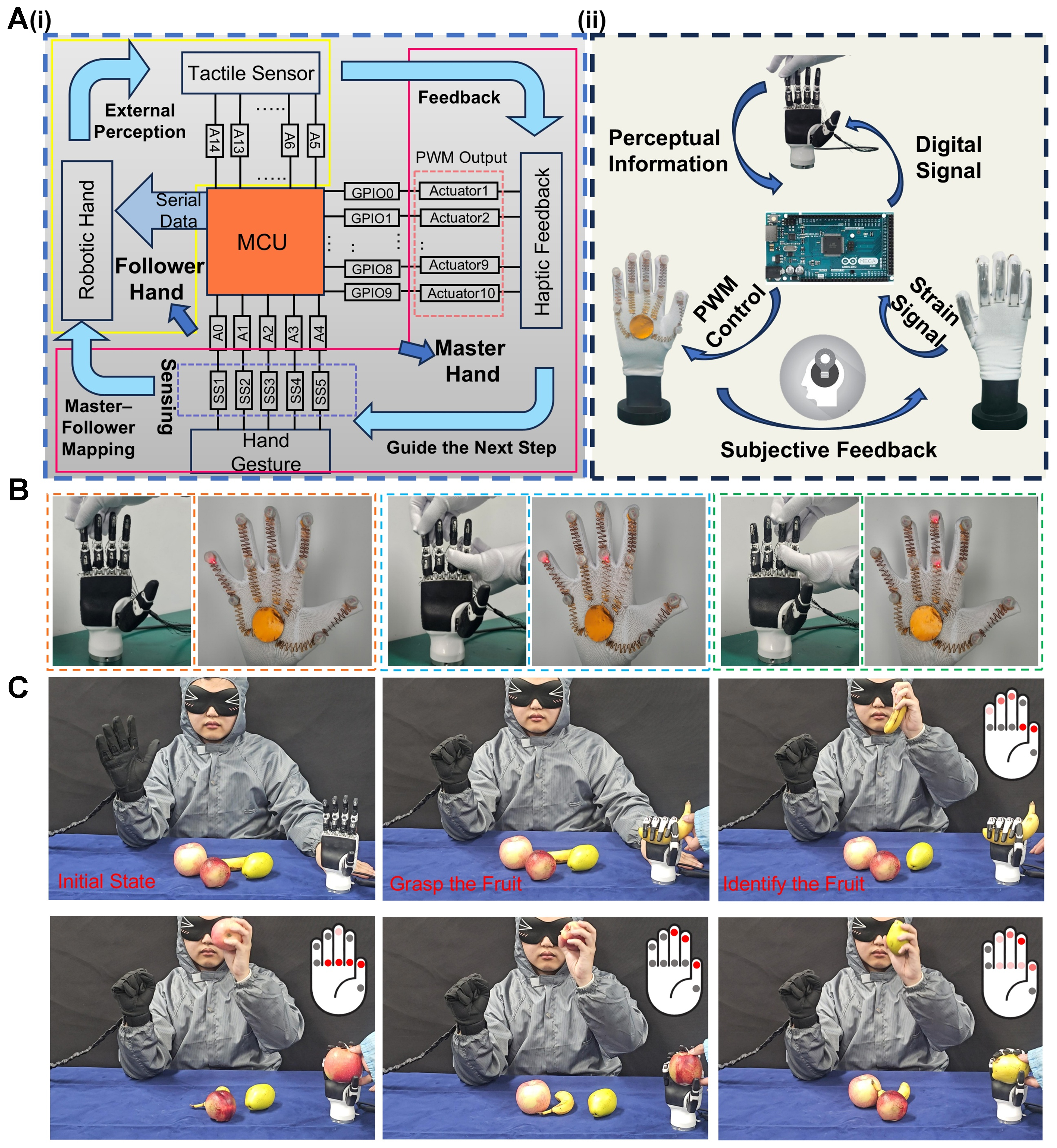
Figure 5. System design and feedback process of the closed-loop HMI system for robotic hand. [A(i)] Operational flowchart of the closed-loop interaction system; [A(ii)] Flowchart of signal processing and feedback; (B) Tactile sensor-triggered actuator operation; (C) Demonstrations of operator-mediated recognition of grasped objects via actuator feedback. (Some image elements are photographs taken by the authors or from open-source websites: FreeImages). HMI: Human-machine interface; MCU: microcontroller unit; PWM: pulse-width modulation.
For output control, the system employs PWM signals to dynamically regulate actuator stimulation intensity. As illustrated in Figure 5A(ii), the operator remotely controls the robotic hand through hand motions by wearing the glove, enabling safe execution of hazardous tasks, such as explosive ordnance disposal. Simultaneously, tactile information from the robotic hand is realistically fed back to the operator. The closed-loop system continuously adapts to variations in the operating environment, optimizing both operational complexity and precision. As shown in Figure 5B, contact events captured by the robotic hand’s tactile array are rendered on the operator’s glove as spatially resolved vibrotactile cues via a fixed one-to-one mapping. Two actuators per finger (fingertip and proximal interphalangeal) provide ten independently addressable channels. Consequently, single- and multi-point contacts elicit concurrent, site-specific activations at the corresponding glove locations, rather than a generic vibration. Programmability is realized through a compact rendering scheme comprising:
(i) Spatial mapping, which selects target channels from the contact distribution;
(ii) Amplitude coding, which maps measured force F to PWM duty cycle via a calibrated transfer function; and
(iii) Temporal coding, which uses brief pulses to mark contact onset/offset and fixed-duration holds to indicate a steady grasp.
In the integrated demonstration [Supplementary Figure 12], the strain-sensor array captures hand gestures and converts them into electrical signals, which are processed by the MCU and host computer to map commands to the robotic hand’s movements. When the robotic hand’s tactile sensors detect an external object, they extract relevant features and transmit them to the MCU, which drives the glove’s vibrotactile actuators via PWM. The operator adjusts contact position and force through the updated vibration amplitude, thereby achieving target recognition followed by a release gesture. As shown in Figure 5C and Supplementary Video 3, the operator grasped fruits with the robotic hand while receiving channel-specific feedback on the glove. The tactile array measured grasp force and contact distribution, which the MCU rendered as position-resolved patterns. The operator could identify the grasped fruit relying solely on this haptic feedback. These results demonstrate that the glove supports precise manipulation and provides a runtime-programmable, multi-channel feedback interface that enhances remote perception. Beyond this integrated demonstration, the same closed-loop mapping generalizes to field scenarios. For example, in defense or hazardous-operation contexts, the system can teleoperate a robotic hand with haptic confirmation of discrete actions (e.g., detecting whether a trigger has been pulled) to ensure precise execution. Similarly, when the robot’s field of view is limited, tactile sensing can compensate for visual occlusions, allowing the robot to infer local contact states and interact accordingly.
Regarding wearability, fit was verified on six volunteers (V1-V6; Supplementary Figure 7), and participants generally reported comfortable wear with no noticeable foreign-body sensation. A prolonged-wear evaluation was also conducted at room temperature (~20 °C; Supplementary Figure 13): 2 h - no visible change; 4 h - mild redness; 6 h - localized perspiration; 8 h - widespread perspiration. These results indicate that heat–moisture buildup primarily occurs after 8 h of continuous wear.
Integrated programmable haptic actuator for wearable navigation
Furthermore, the proposed actuators were integrated into a programmable array for advanced human–machine interaction applications. As illustrated in Figure 6A, the actuators can be flexibly placed not only on the hand but also on various body locations, where they are programmably controlled to enable diverse and intelligent functionalities. In this demonstration, actuators positioned on the back were programmed to provide precise directional guidance. When specific actuator units were activated, localized vibrational feedback delivered clear tactile signals indicating the intended direction of movement to the wearer. For example, as shown in Figure 6B, to guide forward or rightward motion, actuators on the back were sequentially activated, forming distinct tactile patterns (e.g., upward or rightward arrows) that clearly conveyed the direction. Instructions for other directions are provided in Supplementary Figure 14.
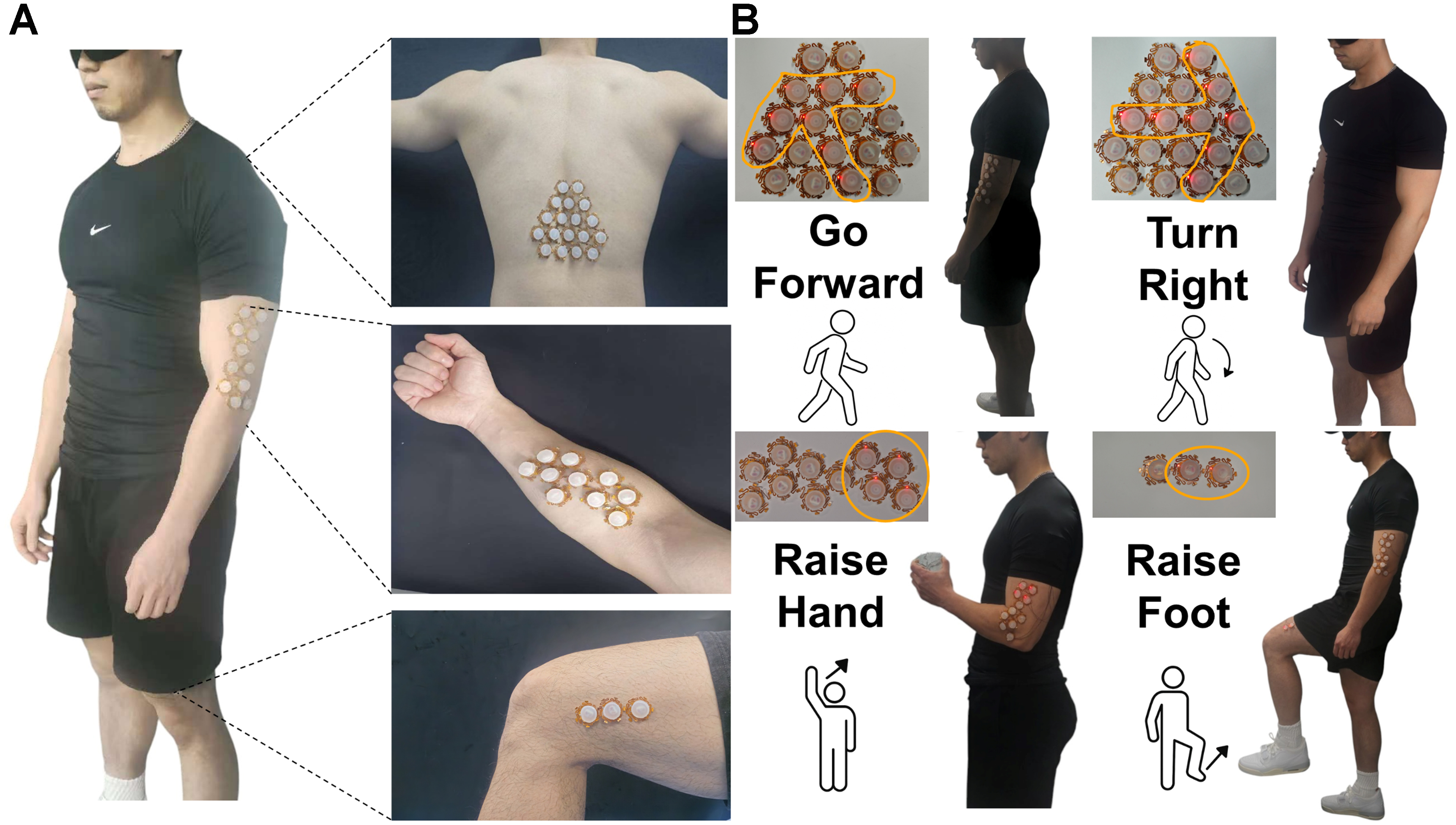
Figure 6. Navigation system using modular feedback actuators. [A(i)] Modular actuator array configurable for different body parts; [A(ii)] Motion guidance via programmable tactile feedback. (Some image elements are photographs taken by the authors or sourced from open-access websites: Freerange).
Similarly, when obstacles were detected in the environment, actuators on the legs generated localized vibrations that prompted the wearer to lift their legs and step over them, enabling intelligent navigation in dynamic and unpredictable settings. Programmable actuators were also integrated on the arms to facilitate motion control. During experiments, an external observer monitored the wearer in real time and transmitted cue commands via Bluetooth to the MCU, which adjusted the actuators accordingly. This allowed the system to modify tactile feedback in real time based on the wearer’s actions, ensuring precise guidance. Supplementary Video 1 demonstrates how the actuators continuously guide the wearer along a designated path and adjust foot-lift height via PWM voltage control when obstacles are encountered. For future work, this hardware setup could be combined with cameras, depth sensors, or light detection and ranging (LiDAR) for automatic perception and fully closed-loop navigation.
CONCLUSIONS
To summarize, we have developed an advanced wearable glove that integrates liquid metal-based strain sensors with programmable electromagnetic actuators, addressing the limitations of conventional HMIs in gesture recognition and tactile feedback. The liquid metal sensors provide high mechanical compliance, sensitivity, and stability under prolonged deformation, enabling accurate detection of complex finger movements. Leveraging a CNN model, the system achieves 98% recognition accuracy across multiple gesture types, demonstrating reliability and precision. On the feedback side, the electromagnetic actuators feature soft form factors, reconfigurability, and voltage-controlled vibrations via PWM, delivering real-time, adjustable haptic stimulation that enhances user immersion and control accuracy. By combining high-performance sensing and feedback in a compact, wearable form, the glove enables closed-loop interaction and intuitive control. This platform shows strong potential for applications in robotics, VR/AR, remote manipulation, and human-in-the-loop systems in challenging environments.
DECLARATIONS
Authors’ contributions
Conceptualization, project administration, resources, supervision, writing - review and editing: Li, D.
Conceptualization, data curation, investigation, methodology, project administration, software, validation, visualization, writing - original draft: Yu, L.
Methodology, visualization: Sun, Y.
Visualization: Huo, W.; Zhou, Z.; Lei, Z.
Software, visualization: Ji, T.
Project administration, funding acquisition: Jiang, F.
Methodology, funding acquisition: Liu, Y.
Supervision, funding acquisition: Zhang, W.
Supervision: Sun, L.
Project administration, supervision, writing - review and editing: Liu, H.
Availability of data and materials
The data that support the findings of this study are available from the corresponding author upon reasonable request.
Financial support and sponsorship
This work was supported by the National Natural Science Foundation of China (NSFC, 62401385), the Natural Science Foundation of Jiangsu Province (BK20240803), the Natural Science Foundation of Jiangsu Higher Education Institutions of China (24KJB460025), and the Open Fund of the State Key Laboratory of Precision Measurement Technology and Instruments (Pilab2413).
Conflicts of interest
All authors declared that there are no conflicts of interests.
Ethical approval and consent to participate
All wearable tests involving human participants were conducted with informed consent. Photographs captured during the experiments showed only external body parts (e.g., palms/hands) and fully complied with relevant ethical guidelines and local regulations, posing no risk or discomfort to participants. As the study did not involve sensitive personal data or commercial interests, a formal ethics review was not required.
Consent for publication
Permission for the use of images from all participants has been obtained.
Copyright
© The Author(s) 2026.
Supplementary Materials
REFERENCES
1. Sun, Z.; Zhu, M.; Shan, X.; Lee, C. Augmented tactile-perception and haptic-feedback rings as human-machine interfaces aiming for immersive interactions. Nat. Commun. 2022, 13, 5224.
2. Zhu, M.; Sun, Z.; Zhang, Z.; et al. Haptic-feedback smart glove as a creative human-machine interface (HMI) for virtual/augmented reality applications. Sci. Adv. 2020, 6, eaaz8693.
3. Zhu, M.; Sun, Z.; Lee, C. Soft modular glove with multimodal sensing and augmented haptic feedback enabled by Materials’ multifunctionalities. ACS. Nano. 2022, 16, 14097-110.
4. Ozioko, O.; Dahiya, R. Smart tactile gloves for haptic interaction, communication, and rehabilitation. Adv. Intell. Syst. 2022, 4, 2100091.
5. Li, Y.; Zheng, C.; Liu, S.; et al. Smart glove integrated with tunable MWNTs/PDMS fibers made of a one-step extrusion method for finger dexterity, gesture, and temperature recognition. ACS. Appl. Mater. Interfaces. 2020, 12, 23764-73.
6. Fischer, S.; Böhmer, C.; Nasrin, S.; Sachse, C.; Cherif, C. Flat-knitted double-tube structure capacitive pressure sensors integrated into fingertips of fully fashioned glove intended for therapeutic use. Sensors 2024, 24, 7500.
7. Lu, W.; Fang, P.; Zhu, M.; et al. Artificial intelligence–enabled gesture‐language‐recognition feedback system using strain‐sensor‐arrays‐based smart glove. Adv. Intell. Syst. 2023, 5, 2200453.
8. Menolotto, M.; Komaris, D. S.; Tedesco, S.; O’Flynn, B.; Walsh, M. Motion capture technology in industrial applications: a systematic review. Sensors 2020, 20, 5687.
9. Shen, S.; Xiao, X.; Yin, J.; Chen, J. Self-powered smart gloves based on triboelectric nanogenerators. Small. Methods. 2022, 6, e2200830.
10. Fan, L.; Zhang, Z.; Zhu, B.; Zuo, D.; Yu, X.; Wang, Y. Smart-data-glove-based gesture recognition for amphibious communication. Micromachines 2023, 14, 2050.
11. Connolly, J.; Condell, J.; O’Flynn, B.; Sanchez, J. T. Gardiner P. IMU sensor-based electronic goniometric glove for clinical finger movement analysis. IEEE. Sens. J. 2018, 18, 1273-81.
12. Calado, A.; Lin, B. S.; Lee, I. J.; Saggio, G. Quasi-static measurement performances of flex-sensor-based and inertial-measurement-unit-based sensory gloves. IEEE. Sens. J. 2024, 24, 2162-171.
13. Lin, B. S.; Lee, I. J.; Yang, S. Y.; Lo, Y. C.; Lee, J.; Chen, J. L. Design of an inertial-sensor-based data glove for hand function evaluation. Sensors 2018, 18, 1545.
14. Wen, F.; Zhang, Z.; He, T.; Lee, C. AI enabled sign language recognition and VR space bidirectional communication using triboelectric smart glove. Nat. Commun. 2021, 12, 5378.
15. Lu, C.; Chen, J.; Jiang, T.; Gu, G.; Tang, W.; Wang, Z. L. A stretchable, flexible triboelectric nanogenerator for self‐powered real‐time motion monitoring. Adv. Mater. Technol. 2018, 3, 1800021.
16. Zhang, H.; Zhang, D.; Wang, Z.; et al. Ultrastretchable, self-healing conductive hydrogel-based triboelectric nanogenerators for human-computer interaction. ACS. Appl. Mater. Interfaces. 2023, 15, 5128-38.
17. Sun, Y.; Chen, T.; Li, D.; et al. Stretchable, multiplexed, and bimodal sensing electronic armor for colonoscopic continuum robot enhanced by triboelectric artificial synapse. Adv. Mater. 2025, 37, e2502203.
18. Lee, J. H.; Kim, S. H.; Heo, J. S.; et al. Heterogeneous structure omnidirectional strain Sensor arrays with cognitively learned neural networks. Adv. Mater. 2023, 35, e2208184.
19. Huang, Q.; Jiang, Y.; Duan, Z.; et al. Ion gradient induced self-powered flexible strain sensor. Nano. Energy. 2024, 126, 109689.
20. Zhang, J.; Zhang, X.; An, X.; et al. Forward design of single ultra-wide range and highly sensitive flexible pressure sensor for multi- physiological-motion monitoring. Adv. Healthc. Mater. 2025, 14, e01798.
21. Ge, C.; An, X.; He, X.; et al. Integrated multifunctional electronic skins with low-coupling for complicated and accurate human-robot collaboration. Adv. Sci. 2023, 10, e2301341.
22. Jin, G.; Sun, Y.; Geng, J.; et al. Bioinspired soft caterpillar robot with ultra-stretchable bionic sensors based on functional liquid metal. Nano. Energy. 2021, 84, 105896.
23. Xu, G.; Wang, H.; Zhao, G.; et al. Self-powered electrotactile textile haptic glove for enhanced human-machine interface. Sci. Adv. 2025, 11, eadh0318.
24. Huang, Y.; Zhou, J.; Ke, P.; et al. A skin-integrated multimodal haptic interface for immersive tactile feedback. Nat. Electron. 2023, 6, 1020-31.
25. Yamaguchi, S.; Hiraki, T.; Ishizuka, H.; Miki, N. Handshake feedback in a haptic glove using pouch actuators. Actuators 2023, 12, 51.
26. Lv, C.; Tian, C.; Jiang, J.; et al. Ultrasensitive linear capacitive pressure sensor with wrinkled microstructures for tactile perception. Adv. Sci. 2023, 10, e2206807.
27. Li, S.; Vogt, D. M.; Rus, D.; Wood, R. J. Fluid-driven origami-inspired artificial muscles. Proc. Natl. Acad. Sci. U. S. A. 2017, 114, 13132-7.
28. Li, Z.; Ma, Y.; Zhang, K.; et al. Air permeable vibrotactile actuators for wearable wireless haptics. Adv. Funct. Mater. 2023, 33, 2211146.
29. Gao, X.; Yang, J.; Wu, J.; et al. Piezoelectric actuators and motors: materials, designs, and applications. Adv. Mater. Technol. 2020, 5, 1900716.
30. Zhou, X.; Wu, S.; Wang, X.; et al. Review on piezoelectric actuators: materials, classifications, applications, and recent trends. Front. Mech. Eng. 2024, 19, 6.
31. Gu, G. Y.; Zhu, J.; Zhu, L. M.; Zhu, X. A survey on dielectric elastomer actuators for soft robots. Bioinspir. Biomim. 2017, 12, 011003.
32. Hajiesmaili, E.; Clarke, D. R. Dielectric elastomer actuators. J. Appl. Phys. 2021, 129, 151102.
33. Ha, K. H.; Yoo, J.; Li, S.; et al. Full freedom-of-motion actuators as advanced haptic interfaces. Science 2025, 387, 1383-90.
34. Jung, Y. H.; Yoo, J. Y.; Vázquez-Guardado, A.; et al. A wireless haptic interface for programmable patterns of touch across large areas of the skin. Nat. Electron. 2022, 5, 374-85.
35. Yu, X.; Xie, Z.; Yu, Y.; et al. A. Skin-integrated wireless haptic interfaces for virtual and augmented reality. Nature 2019, 575, 473-9.
36. Luo, Y.; Liu, C.; Lee, Y. J.; et al. Adaptive tactile interaction transfer via digitally embroidered smart gloves. Nat. Commun. 2024, 15, 868.
37. Zou, X.; Li, X.; Zhang, J.; Pan, Q.; Yang, Z.; Lai, K. W. C. An intelligent glove interface with integrated perceptual simulation and motion tracking for enhanced virtual interactions. Cell. Rep. Phys. Sci. 2024, 5, 102287.
38. Wang, S.; Fang, Y.; He, H.; Zhang, L.; Li, C.; Ouyang, J. Wearable stretchable dry and self‐adhesive strain sensors with conformal contact to skin for high‐quality motion monitoring. Adv. Funct. Mater. 2021, 31, 2007495.
Cite This Article
How to Cite
Download Citation
Export Citation File:
Type of Import
Tips on Downloading Citation
Citation Manager File Format
Type of Import
Direct Import: When the Direct Import option is selected (the default state), a dialogue box will give you the option to Save or Open the downloaded citation data. Choosing Open will either launch your citation manager or give you a choice of applications with which to use the metadata. The Save option saves the file locally for later use.
Indirect Import: When the Indirect Import option is selected, the metadata is displayed and may be copied and pasted as needed.
About This Article
Special Topic
Copyright

Data & Comments
Data
0


Comments
Comments must be written in English. Spam, offensive content, impersonation, and private information will not be permitted. If any comment is reported and identified as inappropriate content by OAE staff, the comment will be removed without notice. If you have any queries or need any help, please contact us at [email protected].