


Synchrotron X-ray and neutron diffraction study on the deformation and phase transformation mechanisms in TiAl alloys: a review
 0
0 
Abstract
TiAl alloys are considered promising candidates for high-temperature structural applications, primarily because of their low density and good high-temperature performance. However, their broader application remains restricted due to poor ductility and inadequate deformation compatibility. The (α2+γ) lamellar structure, which dominates the service microstructure, exhibits strong deformation anisotropy. Moreover, the large plasticity difference between the α2 and γ phases leads to pronounced inhomogeneous deformation. Accordingly, internal stress accumulates in the α2 phase and may initiate cracks at the α2/γ interfaces. The formation of deformation textures further influences the microscopic deformation and complicates the analysis of stress distribution. Understanding the underlying deformation mechanisms and stress evolution requires real-time observation of these dynamic processes. To this end, synchrotron X-ray diffraction and neutron diffraction are employed for their deep penetration capability and high spatial and temporal resolution. These advanced techniques enable in situ tracking of lattice strain evolution, load partitioning, and phase transformation. This review highlights the deformation behavior of TiAl alloys, including their elastic and plastic responses, texture evolution, and internal stress accumulation. Particular attention is given to the reversible stress-induced α2→O phase transformation, which presents promising opportunities for enhancing mechanical performance through targeted microstructural optimization.
Keywords
INTRODUCTION
Advancements in aerospace technology have imposed increasingly stringent requirements on
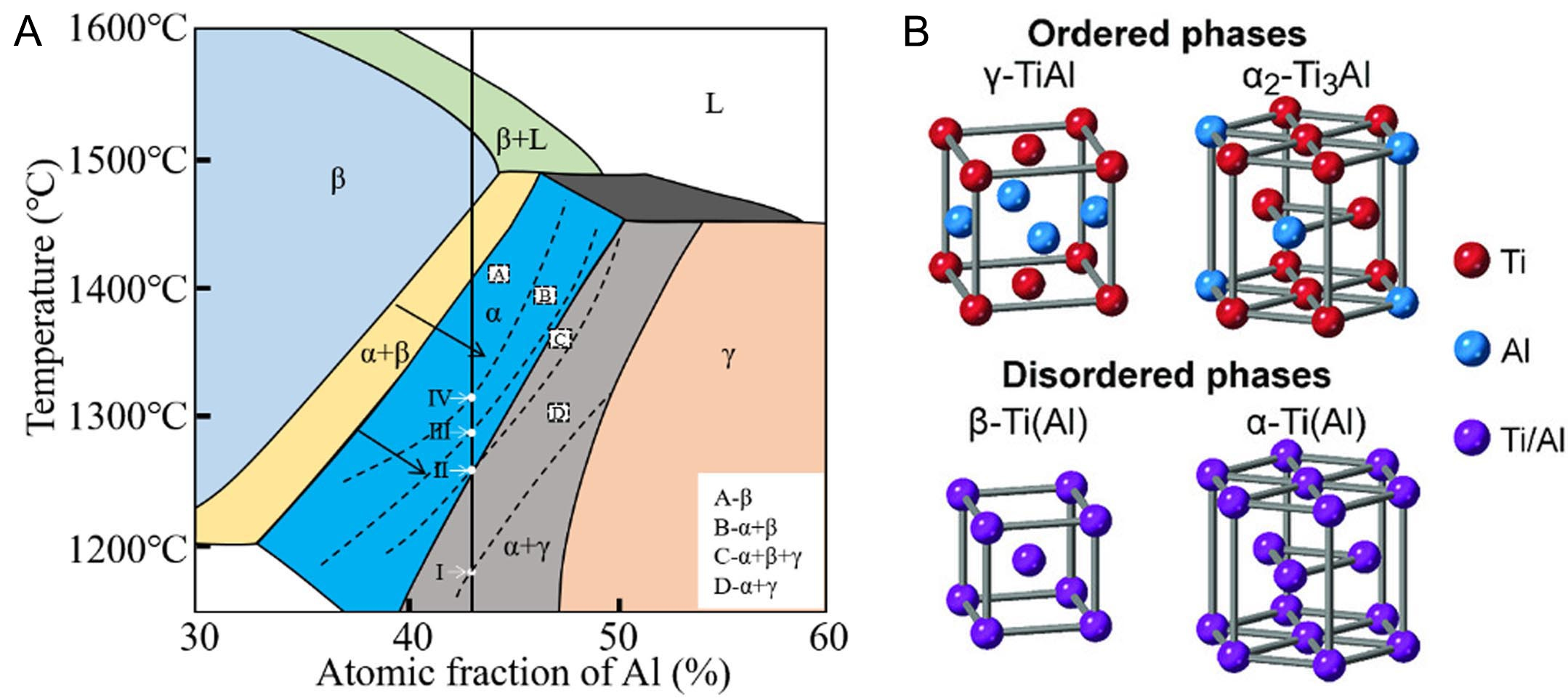
However, the insufficient ductility of TiAl alloys remains one of the major challenges limiting their widespread application. Figure 1A shows a schematic of the Ti-Al phase diagram in the presence of
Phase transformation under mechanical loading is another crucial aspect in understanding the deformation mechanisms of TiAl alloys. The α2 phase, whose chemical composition generally deviates from equilibrium, has a strong disposition to decompose into γ and ωo phases during long-time annealing[24-27]. This transformation process is not only thermally driven but can also be significantly accelerated by externally applied stress, particularly at elevated temperatures[28-31]. In addition, the orthorhombic O phase, which has demonstrated good plasticity in Ti2AlNb alloys[32], would precipitate from the α2 matrix, forming a modulated (α2+O) microstructure in γ-TiAl alloys[33]. The emergence of the O phase complicates microstructural evolution but also offers a potential pathway to improve the ductility and mechanical performance. As a note, alloying with elements such as Nb or V is essential for the O phase formation[34]. These alloying elements are pivotal in stabilizing the O phase, making their addition essential in alloy design strategies aimed at tailoring phase stability and mechanical properties. Furthermore, previous studies have suggested that the presence of volume and coherency stresses within the (α2+γ) lamellar structures is a prerequisite for O phase formation during heat treatment[33,35]. Specifically, α2/γ lamellar interfaces and grain boundaries with severe stress concentration are energetically favorable for the O phase precipitation. Interestingly, the temperature range for the O phase (500-750 °C) is close to the expected service temperatures of TiAl alloys (above 800 °C)[3,36]. This proximity suggests the possibility of stress-induced α2 to O phase transformation during actual service conditions. In fact, recent experimental investigations have observed reversible stress-induced O phase formation at 800 °C and even 900 °C, offering new opportunities for advanced microstructural design and optimization[37].
High-energy X-ray diffraction (HEXRD) using synchrotron radiation, together with neutron diffraction techniques, serves as a powerful tool to observe dynamic processes. In contrast to conventional
ADVANTAGES OF SYNCHROTRON X-RAY AND NEUTRON DIFFRACTION
Synchrotron X-ray and neutron diffraction are widely regarded as complementary techniques for exploring the microstructural evolution of metallic alloys. Due to their fundamentally different interactions with matter, each method offers unique advantages in probing distinct material characteristics. Synchrotron XRD involves the interaction of high-energy photons with the electron clouds surrounding atomic nuclei. As the resulting diffraction patterns are directly related to electron density, synchrotron XRD is especially effective for identifying phase compositions, determining crystal structures, and analyzing internal stress states. In the case of TiAl alloys, synchrotron HEXRD enables a clear distinction between phases such as
Neutron diffraction, by contrast, is based on the interaction between neutrons and atomic nuclei, making it highly sensitive to atomic positions, isotopic variations, and subtle lattice displacements. Unlike X-rays, neutrons are unaffected by electron density and can deeply penetrate materials, making them ideal for examining bulk structures and internal stress fields in large or dense samples. Neutron diffraction is especially useful for studying complex phases because it can detect long-range atomic ordering and displacive transformations that X-rays may not resolve. For example, the orthorhombic O phase in TiAl alloys exists in two variants, i.e., O1 and O2, that differ primarily in atomic ordering rather than overall composition[38]. Neutron diffraction can distinguish these subtle structural variations through changes in reflection intensity, even when atomic displacements are small. Such fine details may be overlooked by
Taken together, synchrotron HEXRD and neutron diffraction provide a more comprehensive understanding of the complex microstructural behavior in TiAl alloys. While synchrotron HEXRD offers high-resolution analysis suitable for phase identification, strain mapping, and real-time monitoring, neutron diffraction complements it by probing bulk structures and revealing ordering transitions and atomic-scale displacements. The integration of both techniques not only enriches fundamental insights into phase transformations and deformation mechanisms but also plays a pivotal role in the development and optimization of next-generation intermetallic alloys for demanding aerospace and structural applications.
DEFORMATION COMPATIBILITY BETWEEN α2 AND γ PHASES
Origin and characterization of internal strains
In polycrystalline materials, plastic deformation typically initiates asynchronously across grains, with the deformation behavior varying depending on the crystallographic orientation of individual grains relative to the applied loading direction (LD). This asynchrony is especially pronounced in multiphase alloys, where the critical resolved shear stress (CRSS) values of different slip systems in the constituent phases differ significantly. As a result, neighboring grains must adapt to this inhomogeneous elastoplastic deformation to maintain interfacial continuity, which leads to the generation of elastic strains, commonly known as intergranular strains[39-44]. These intergranular strains, fluctuating at the grain scale, are partially preserved as type II strains after unloading due to irreversible plastic deformation[39]. The intergranular strain evolution is complex, collectively governed by multiple factors, including grain size, texture, and microstructure. These strains are crucial for understanding the deformation response of materials, as they contribute significantly to microstructural evolution by driving strain localization, damage initiation, and crack propagation during loading.
The lattice strain evolution of constituent phases within a polycrystalline material serves as an effective assessment for load partitioning and intergranular strain variation. The lattice strain for selected {hkl} reflections is estimated as[45]:
Where dhkl and
In synchrotron HEXRD experiments, strain states in deformed components can be comprehensively mapped by rotating the sample[46-49]. As shown in Figure 2A, when the specimen is rotated around the radial direction (RD), more diffracting planes would satisfy the diffraction condition and contribute to the measurement[50]. Specifically, this rotation extends the measurement range from the crystal plane normal being perpendicular to the incident beam to the crystal plane normal positioned on an arbitrary plane parallel to the RD, thereby facilitating a more comprehensive analysis of lattice strain in different directions. The acquired raw data are visualized by constructing generalized pole figures, which plot lattice strain or peak intensity as a function of azimuth angle ƞ and rotation angle ω. As shown in Figure 2B, each great circle projected along the hoop direction (HD) represents specific parameters (such as peak intensity and lattice strain) changing with ƞ at a fixed ω. Additionally, the position of each great circle shifts as ω changes, gradually establishing the pole figures (derived from intensity distribution) and strain pole figures (derived from lattice strain distribution, Figure 2C). First introduced by Wang et al.[51-53], strain pole figures offer an overall visualization of the spatial distribution of intergranular strains by projecting them onto a
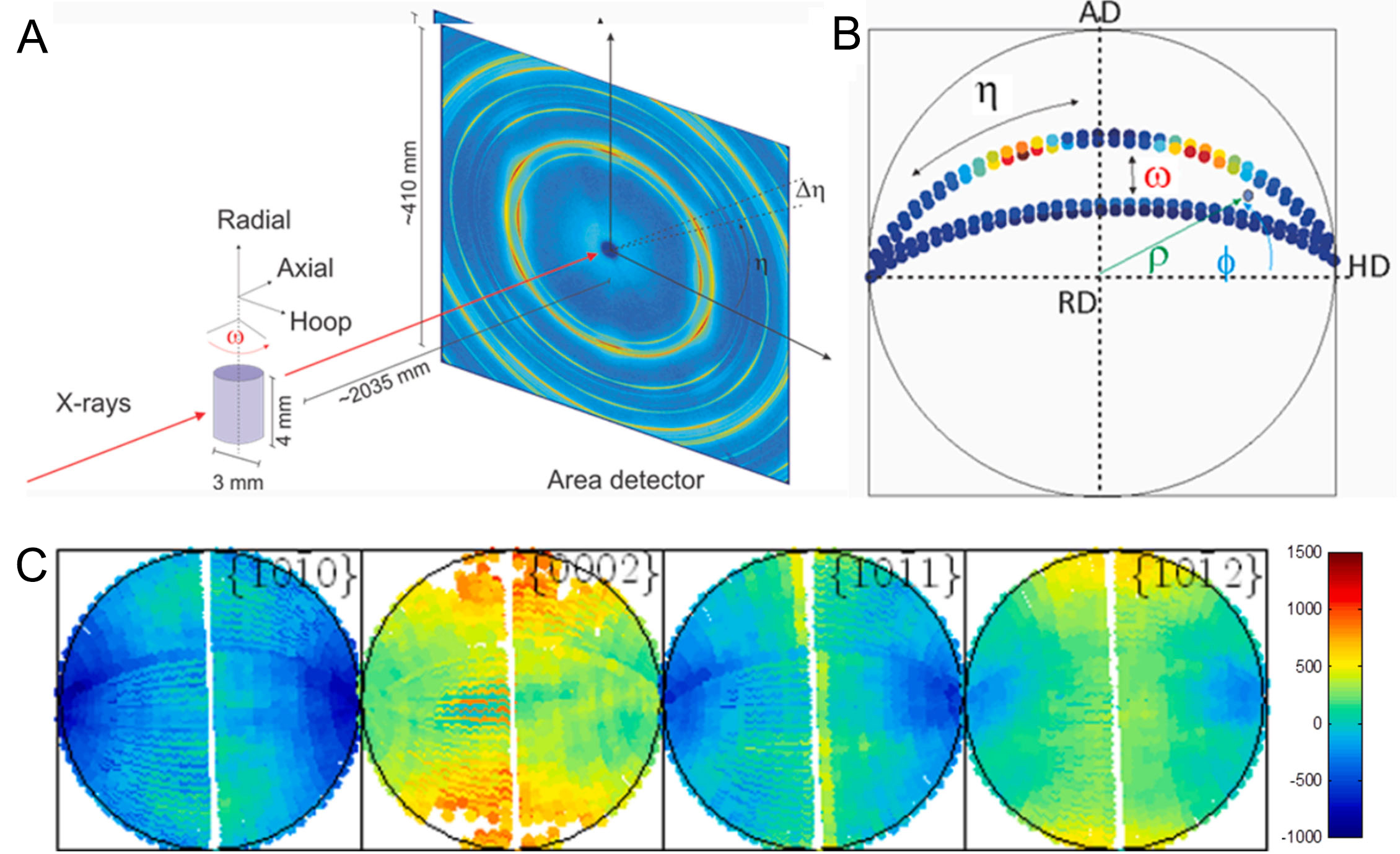
Figure 2. (A) Schematic illustration of the experimental configuration used for in situ HEXRD measurements. The sample is aligned with the axial direction (AD) parallel to the X-ray beam, the hooping direction (HD) horizontal, and the radial direction (RD) vertical. To analyze the peak profiles of grains with different orientations, the specimen rotates around the RD; (B) Construction of a stereographic projection, where each point encodes information such as peak intensity and lattice strain, defined by the azimuth angle (η) and the rotation angle (ω); (C) Experimental strain pole figures. (Reproduced from Ref.[50][50]). HEXRD: High-energy X-ray diffraction.
During uniaxial tension and compression experiments, lattice strains typically exhibit periodic variations as the crystal direction gradually shifts away from the LD. As the sample is rotated around the transverse direction (TD), the lattice strains exhibit similar changing trends at different rotation angles[54]. Specifically, tensile stresses increase as grain orientations approach the LD, while the TD experiences the highest compressive stresses during tensile tests. In fact, this situation is widely applicable and also observed in multicomponent metallic glassy alloys, where the LD experiences the highest tensile stresses, and the TD endures the highest compressive stresses. Notably, crystal directions deviating 60° from the LD are almost unstrained[55]. In general, lattice strains along the LD and TD reflect the most extreme stress conditions and are commonly used to investigate load partitioning behavior and internal stress evolution.
In face-centered cubic (FCC) metals, as demonstrated by Dye et al.[39], the lattice strains of all reflections along LD respond linearly to bulk stresses during elastic deformation [Figure 3A]. Above macro-yielding, load partitioning between differently oriented grains becomes significant. At this stage, the lattice strains deviate from their initial linear elastic response and display distinct trends. The loads borne by plastically deformed grains no longer increase, and may even decrease, as evidenced by the reduction in the lattice strains of <220>//LD oriented grains with increasing bulk stress. Simultaneously, more load is transferred to elastically deformed grains, as indicated by an inflection point in the lattice strain evolution of <002>//LD oriented grains, followed by a rapid increase. This load partitioning is accompanied by intergranular strain accumulation, which is positively correlated with the degree of deviation from linear elastic behavior, as described by the following equation[40]:
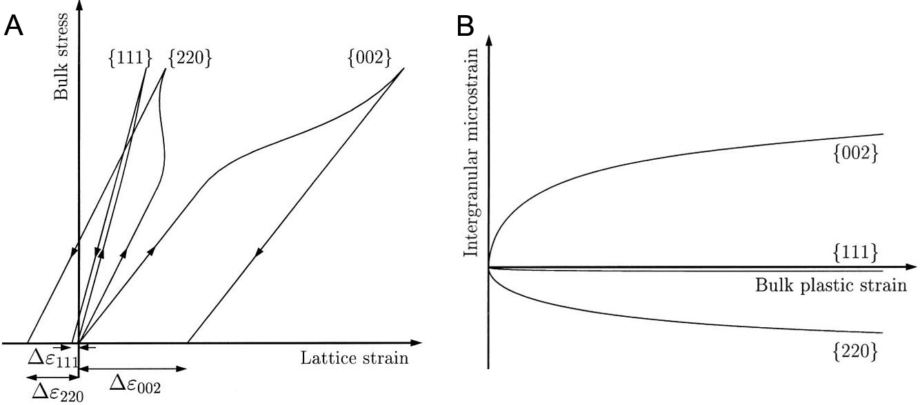
Figure 3. (A) Bulk stress vs. lattice strain curves for grains with normals parallel to the loading direction (LD) in face-centered cubic (FCC) metals; (B) Intergranular microstrain vs. bulk plastic strain curves in FCC metals. (Reproduced from Ref.[39][39]).
Where σapp and Ehkl represent the applied stress and elastic diffraction constant, respectively,
For cylindrical samples, σ11 and σ22 represent the principal stress along LD and TD, σ33 is equivalent to σ22.
Particularly, designing next-generation multiphase alloys such as TiAl alloys for high-performance applications, such as those in aerospace, automotive, and energy industries, presents a key challenge in controlling the microstructure to optimize internal stress distribution. Developing alloys that offer a balance of high strength, toughness, and fatigue resistance requires a thorough understanding of how these materials deform at the microstructural level, especially at grain boundaries where internal stresses accumulate.
Internal stress accumulation in the α2 phase
In TiAl alloys, the α2 phase with an ordered hexagonal structure plays a critical role in governing the overall deformation behavior. Due to its high strength and low plastic deformability, stress accumulation within the α2 phase can accelerate crack initiation, particularly at α2/γ interfaces, leading to premature failure of the alloy. Intergranular stress accumulation in the α2 phase is mainly influenced by the activation of slip systems in the α2 and γ phases, as well as by microstructure and texture formation. Plastic deformation in the α2 phase is largely restricted to 1/3(1
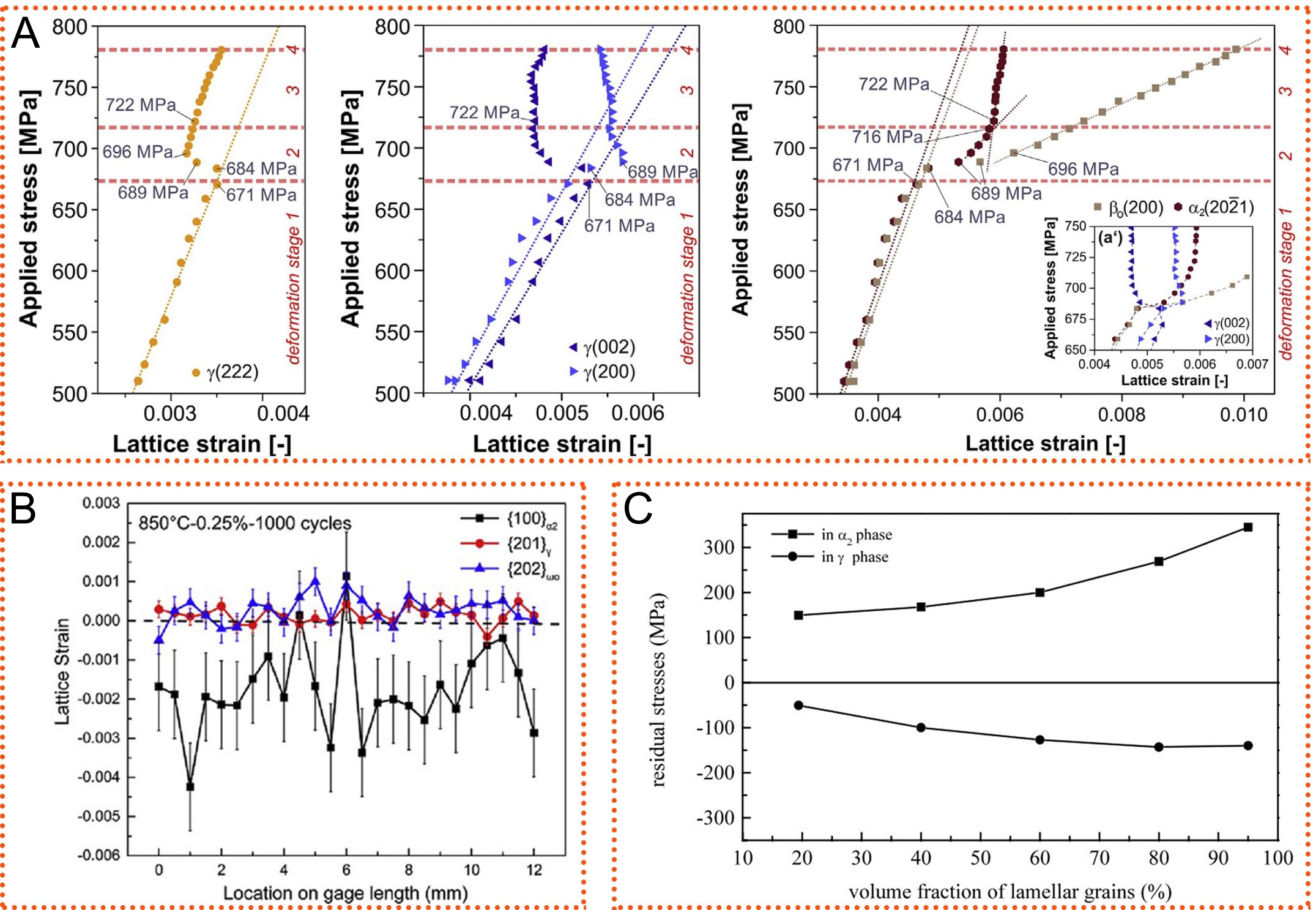
Figure 4. (A) True stress vs. lattice strain curves for the α2, γ, and βo reflections. Equiaxed grained TNM-TiAl alloys were stretched at room temperature. (Reproduced from Ref.[61][61]); (B) Development of the lattice strains revealed by sample gage length scanning interrupted at 1000 cycles in the fatigue deformation of high Nb-TiAl alloy at 850 °C. (Reproduced from Ref.[62][62]); (C) Residual stresses of the α2 and γ phases varying with increasing volume fraction of the lamellar structures. (Reproduced from Ref.[11][11]).
The distribution and morphology of the (α2+γ) lamellar structures in the microstructure strongly influence internal stress accumulation in the α2 phase[11,63,64]. In deformed TiAl alloys, Guo et al.[11] found that residual stress in the α2 phase is positively correlated with the volume fraction of the lamellar structures. The residual stress in the α2 phase in a microstructure containing 95% lamellar structures is twice that of one with 20% lamellar structures, as shown in Figure 4C. During in situ HEXRD compression, Liu et al.[65,66] found that the α2 and γ phases in a nearly lamellar Ti-45Al-8Nb-0.2W-0.2B-0.02Y alloy exhibit different deformation behavior and internal stress evolution compared to those in the duplex microstructure (mainly consisting of equiaxed α2 and γ grains) with the same composition. In the nearly lamellar microstructure, deformation in the γ phase proceeds through sequential activation of ordinary dislocations and mechanical twinning at stress levels of 200 MPa and 585 MPa, respectively. In contrast, plastic deformation of the α2 phase occurs within a relatively narrow stress window of 775-850 MPa during the late strain hardening stage, as illustrated in Figure 5A. At 850 MPa, the Von-Mises stress in the α2 phase is nearly three times higher than that in the γ phase [Figure 5B]. In the duplex microstructure, plastic deformation in the γ and α2 phases initiates at stresses of 370 and 670 MPa, respectively [Figure 5C]. The Von-Mises stress in the α2 phase is at most 2.5 times higher than that in the γ phase. These differences in internal stress accumulation between microstructures mainly originate from the strong deformation anisotropy of the lamellar structure.
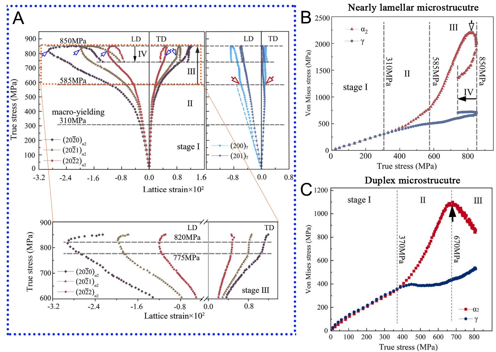
Figure 5. Compression behavior of Ti-45Al-8Nb-0.2W-0.2B-0.02Y alloys with (A and B) nearly lamellar and (C) duplex microstructures at 800 °C. (A) True stress-lattice strain curves for α2 and γ reflections; a detailed view of the α2 lattice strain evolution in stage III is provided below. (Reproduced from Ref.[65][65]); (B and C) Von-Mises stress of α2 and γ phases plotted against true stress for (B) the nearly lamellar (Reproduced from Ref.[65][65]) and (C) the duplex microstructure (Reproduced from Ref.[66][66]).
Within the lamellar structures, the α2 and γ phases follow the well-known Blackburn OR: {111}γ//(0001)α2, <110]γ//<11
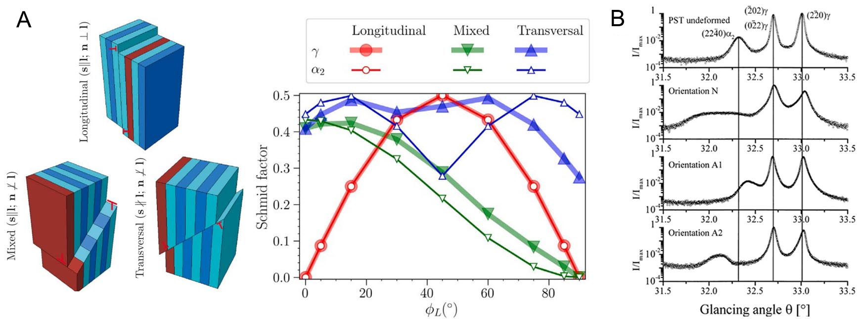
Figure 6. (A) Activation of different slip systems in differently oriented (α2+γ) lamellar structures relative to the load axis (on the left) and Schmid factor variation of different slip systems in α2/γ lamellar structures as they deviate from the load axis within an angle range of 0°-90° (on the right). (Reproduced from Ref.[68][68]); (B) XRD profiles of differently oriented PST-TiAl alloys deformed at room temperature. (Reproduced from Ref.[14][14]). XRD: X-ray diffraction.
The tilted basal and transverse textures, where the c axis is slightly misaligned from the LD and oriented along the TD, represent typical deformation textures in the α2 phase[69-74]. Stark et al.[75] investigated the texture evolution of the α phase during hot compression at 1,230 °C. Initially, the intensity of the (0002)α reflections is randomly distributed along the azimuth angle, indicating a weakly textured initial microstructure. As compression proceeds, the intensity of the (0002)α reflections gradually shifts toward the LD. When the strain reaches 20 %, the intensity of the (0002)α reflections becomes concentrated in a direction approximately 20° off the LD. The intensity evolution along the azimuth angle implicitly reflects the deformation texture evolution. The (0002)α pole figures further confirm that the α phase develops a tilted basal fiber texture at a strain of 20%, although this texture is slightly weakened by flow softening in subsequent deformation. For hexagonal phases with a c/a ratio less than 1.63, the c axis tends to align with the compression direction, resulting in the formation of a basal texture[76-78]. However, during hot rolling in the (α+β) or (α+β+γ) phase regions, TiAl sheets exhibit not only a basal texture but also a transverse texture component, as illustrated in Figure 7[72]. This transverse texture is thought to form only in the presence of a softer secondary phase and is closely linked to the dominant activation of slip systems within that phase[71,72]. It should be noted that the α2 orientation in the basal texture refers to the c axis parallel to the load axis, which is the same case as the orientation N mentioned above. In other words, basal texture formation is unfavorable for subsequent deformation and would trigger a rapid internal stress accumulation in the α2 phase.
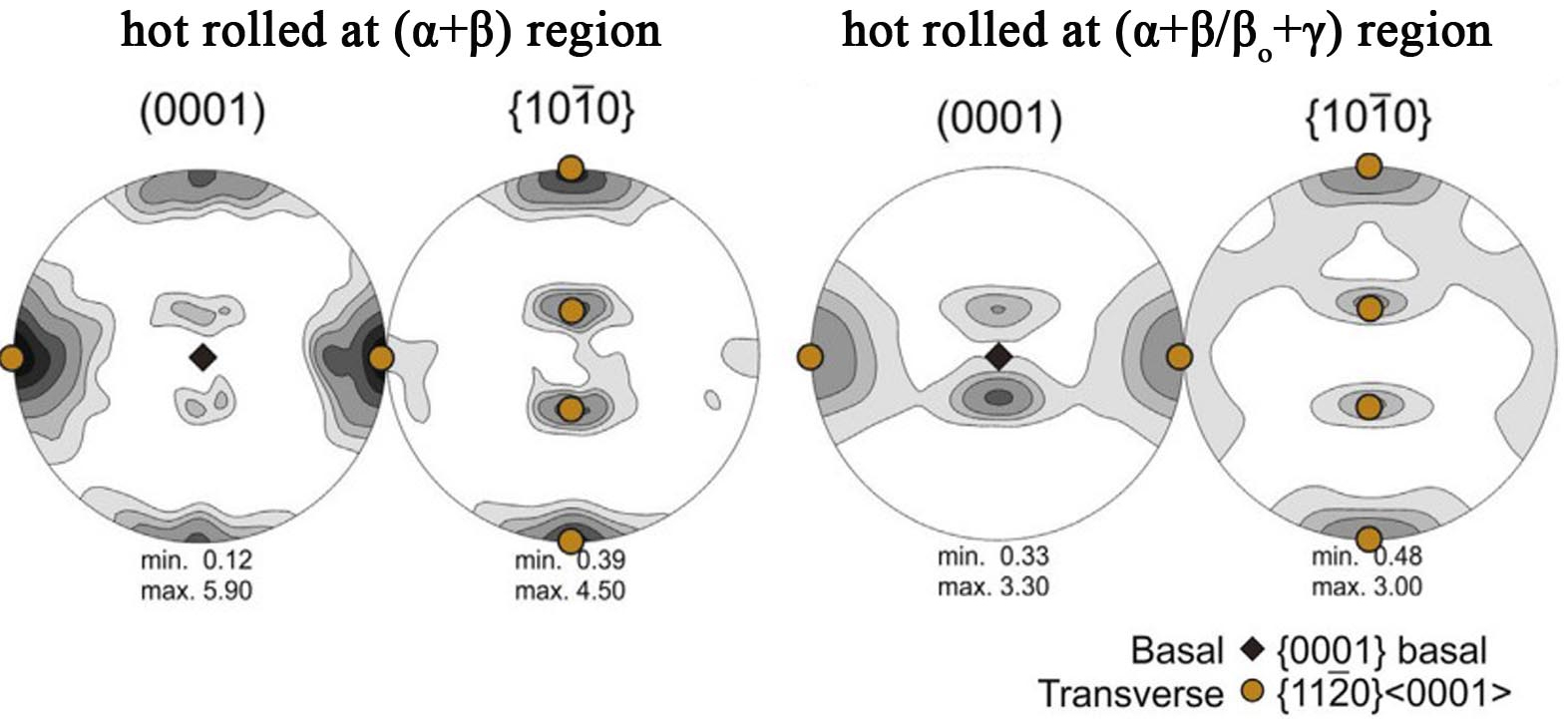
Figure 7. Pole figures of the α2 phase in a Ti-43Al-4Nb-1Mo-0.1B alloy hot rolled in different phase regions. The RD is aligned vertically, and the TD horizontally. (Reproduced from Ref.[72][72]). RD: Radial direction; TD: transverse direction.
In practice, texture evolution and plastic deformation usually interweave during deformation, jointly influencing internal stress evolution in the alloy. Characterized by HEXRD, the microscopic deformation mechanisms of the α2 phase in TiAl alloys during uniaxial compression have been investigated. At a stress level of 650 MPa, the intensity distribution of the α2 reflections suggests that the development of α2 texture is at an early stage. As visible in Figure 8A and B, the intensity of the (20
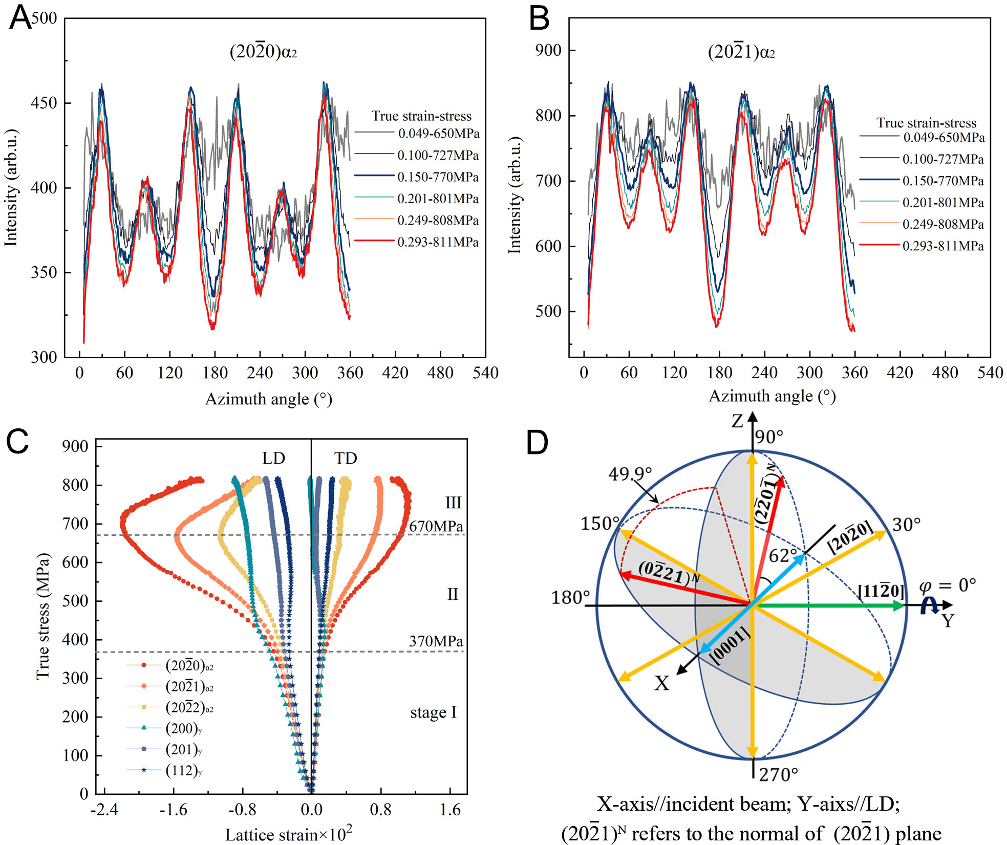
Figure 8. A duplex Ti-45Al-8Nb-0.2W-0.2B-0.02Y alloy subjected to compression at 800 °C. (A and B) Azimuthal intensity distributions for the (20
In general, the deformation behavior of TiAl alloys exhibits significant complexity due to the anisotropic nature of the α2 phase and the (α2+γ) lamellar structures. The orientation-dependent deformation response of the lamellar structure makes the overall deformation behavior of TiAl alloys highly sensitive to both applied stress and temperature fluctuations. Further compounding this complexity, grain reorientation induced by texture development disrupts deformation coordination in the α2 phase while simultaneously influencing internal stress accumulation. Additionally, the chemical composition of the α2 phase generally deviates from the equilibrium state and has a strong disposition to decompose, such as α2→γ and α2→ωo[24-27]. This process is significantly accelerated by accumulated internal stress[28-31]. The orthorhombic O phase, typically observed during long-term annealing, would precipitate from the α2 phase under stressed conditions, further complicating the deformation dynamics. This phase not only generates additional internal stresses but also interacts with existing stress fields within the α2 phase. These interactions highlight the critical need for detailed investigations into the coupled evolution of internal stresses and stress-induced phase transformations. Such research is essential for elucidating the fundamental deformation mechanisms governing TiAl alloys, particularly regarding the complex interplay between microstructural evolution and mechanical response.
α2 TO O PHASE TRANSFORMATION IN TIAL ALLOYS
Overview of O phase precipitation
Banerjee et al.[32,79,80] first reported the existence of an ordered orthorhombic O phase with Cmcm symmetry in a Ti3Al-based alloy with a high Nb content (Ti-25Al-12.5Nb). They suggested that the O phase originates from the slightly distorted α2 phase with a nominal composition of Ti2AlNb. Subsequently, Muraleedharan et al.[38] discovered two different structures of the O phase, i.e., O1 and O2, which possess the same crystal structure and symmetry but differ in atomic occupancy. Ti and Nb atoms randomly occupy the Wyckoff positions 8g and 4c2 in the O1 structure, while Ti atoms predominantly occupy the 8g position, and Nb atoms primarily occupy the 4c2 position in the O2 structure. Except for the α2 phase, the O phase could also transform from the βo matrix. Bendersky et al.[81] found that the addition of Nb affects the formation path of the O phase. In the Ti-25Al-12.5Nb alloy, the O phase originates directly from the α2 phase, whereas in the Ti-25Al-25Nb alloy, the βo phase transforms into the O phase via an intermediate B19 phase with Pmma symmetry.
Early studies on the orthorhombic O phase mainly focused on the Ti-Al-Nb ternary alloys with compositions of Ti-(12-31)Al-(12.5-37.5)Nb[79-81]. In the 21st century, researchers also observed the presence of the orthorhombic phase in γ-TiAl alloys. In Ti-(40-44)Al-8.5Nb alloys, Appel et al.[82-84] found modulated microstructures composed of the βo phase and an orthorhombic phase using transmission electron microscopy (TEM). The orthorhombic phase in this study was recognized as the B19 phase, transformed by a shuffle displacement of adjacent (110) planes along opposite [1
During in situ heating and cooling experiments in a lamellar Ti-42Al-8.5Nb alloy, Rackel et al.[35] observed peak splitting of the α2 reflections caused by orthorhombic phase precipitation. Employing both the B19 and O phase structural models for Rietveld refinement, the fitting results showed that the orthorhombic phase is structurally comparable to the O phase, as visible in Figure 9A. This indicates that the orthorhombic phase precipitating from the α2 lamellae is, in fact, the O phase. Furthermore, the temperature range for the stability of the O phase was determined to be 500-700 °C. Additional evidence identifying the orthorhombic phase as the O phase was advanced by TEM observation[33]. Theoretically, the O phase with lower symmetry should exhibit more diffraction spots compared to the B19 phase. Gabrisch et al.[33] simulated the electron diffraction patterns of the α2, B19, and O phases. Under the [1
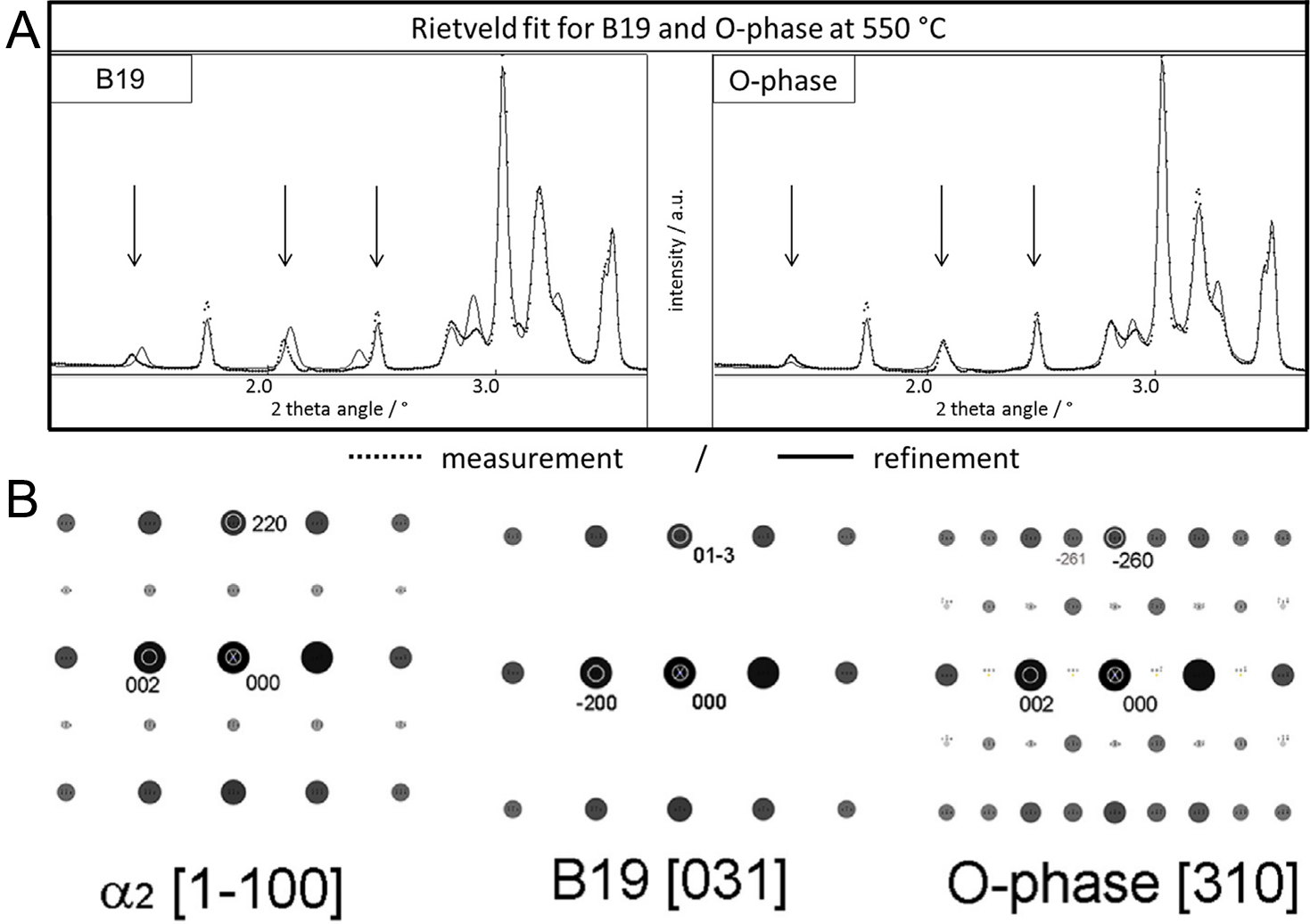
Figure 9. (A) Rietveld refinement using structural models of the B19 and O phases. (Reproduced from Ref.[35][35]); (B) Simulated diffraction patterns in the [1
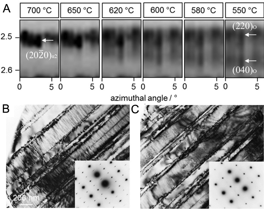
Figure 10. In situ (A) HEXRD and (B) and (C) TEM heating of a Ti-42Al-8.5Nb alloy: (A) the (20
Studies examining the temperature range of O phase formation across different alloy compositions have been conducted in γ-TiAl alloys. As evidenced by orthorhombic splitting of the α2 reflections, the O phase forms out of the α2 phase after annealing at 550 °C for 20 h when the Nb content exceeds 5-7.5 at.% and the Al content is below 46-47 at.%[34]. In a Ti-42Al-8.5Nb alloy, TEM observations have directly identified nanoscale O phase domains embedded within the α2 phase following annealing at 550 °C and 650 °C[33]. In a lamellar Ti-45Al-8.5Nb alloy, modulated structures, associated with O phase formation within the α2 lamellae, were observed after annealing at 650 °C and disappeared upon heating to 700 °C[88,89]. A comparative study has been conducted to examine the effect of alloy composition on O phase formation in Ti-(43-47)Al-8.5Nb and Ti-45Al-(4-10)Nb alloys[36]. The results demonstrated that while increasing Nb content and decreasing Al concentration elevate the dissolution temperature of the O phase, it remains below 750 °C. In general, the maximum temperature at which the O phase remains stable before dissolving is close to the typical service temperature of high Nb-containing TiAl alloys (i.e., above 800 °C).
Formation mechanisms of the O phase
The crystal structure of the O phase remains controversial. Previous studies suggested that two crystal structures, O1 and O2, can be differentiated by the ordered parameter (η), which quantifies the difference in Nb occupancy between the Wyckoff positions 4c2 and 8g within Cmcm symmetry[38]. Specifically, the O1 phase corresponds to η = 0 with Nb atoms randomly occupying the 8g and 4c2 positions, while the O2 phase is defined by η > 0.2. Furthermore, η = 1 represents the fully ordered state, where the Nb atoms exclusively occupy the 4c2 positions. In Ti-27.5Al-xNb ternary alloys, the O2 to O1 structural transition was once considered to take place during heating, as illustrated in Figure 11A[38]. However, using in situ neutron diffraction heating experiments, Xu et al.[90] found that only one crystal structure of the O phase exists, i.e., O2. The difference in atomic occupancy (i.e., different η) of the O1 and O2 structures causes intensity changes in the O reflections, as visible in Figure 11B. However, during continuous heating, especially within the structural transition temperature range of O2 to O1, the intensity of the O reflections remains the same (magnified view shown on the right in Figure 11C). Further Rietveld refinement demonstrated that the O phase maintains an O2 crystal structure. Additionally, within the stable temperature range of 750-950 °C of the O phase, the order parameter (η) fluctuates between 0.4 and 0.5, which aligns with the study reported by Mozer et al.[91] (see Table 1). These results indicate that the βo to O phase transformation involves not only a structural distortion but also a significant change in atomic ordering in Ti3Al-based alloys. However, the situation becomes different when considering the α2 to O phase transformation in γ-TiAl alloys. The Nb atoms of the O lattice show no preferential occupancy in the 4c2 position, and this structure is identified as the O1 structure[35]. Additionally, TEM evidence further supported the presence of the O1 structure in a
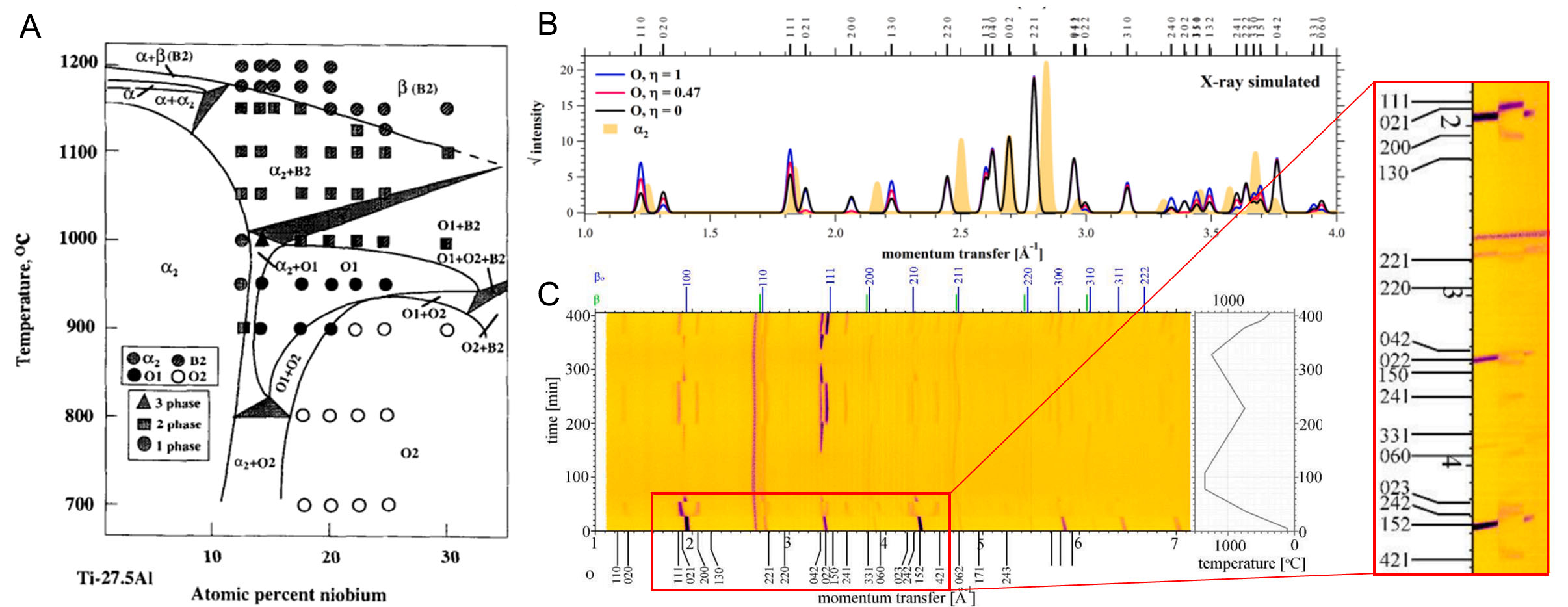
Figure 11. (A) Ternary Ti-27.5Al-xNb phase diagram. (Reproduced from Ref.[38][38]); (B) Simulated XRD patterns of the O phase with the chemical composition of Ti2AlNb; (C) Variation of the Ti-24.8Al-24.3Nb neutron diffraction pattern at different temperatures. (Reproduced from Ref.[90][90]). XRD: X-ray diffraction.
The crystal structures of the O phase reported by Mozer et al.[91], Xu et al.[90], and Rackel et al.[35]
| Temperature (°C) | Wyckoff position | Site occupancy (%) | Lattice parameter (Å) | Order parameter |
| 700 °C[91] | 8g | 18 Nb 82 Ti | a = 6.0893 b = 9.5694 | 0.469 |
| 4c1 | 100 Al | c = 4.6666 | ||
| 4c2 | 65 Nb 35 Ti | |||
| 750 °C[90] | 8g | 14.58 Nb 85.42 Ti | a = 6.1479 b = 9.6031 | 0.4981 |
| 4c1 | 100 Al | c = 4.6877 | ||
| 4c2 | 64.39 Nb 35.61 Ti | |||
| 550 °C[35] | 8g | 15 Al 75 Ti 10 Nb | a = 5.918 b = 9.801 c = 4.673 | |
| 4c1 | 15 Al 66 Ti 19 Nb | |||
| 4c2 | 95 Al 5 Ti |
Research has been conducted to explore the formation mechanisms of the O phase, particularly the compositional and structural transitions involved in the α2→O phase transformation[33,88,89,92]. In a
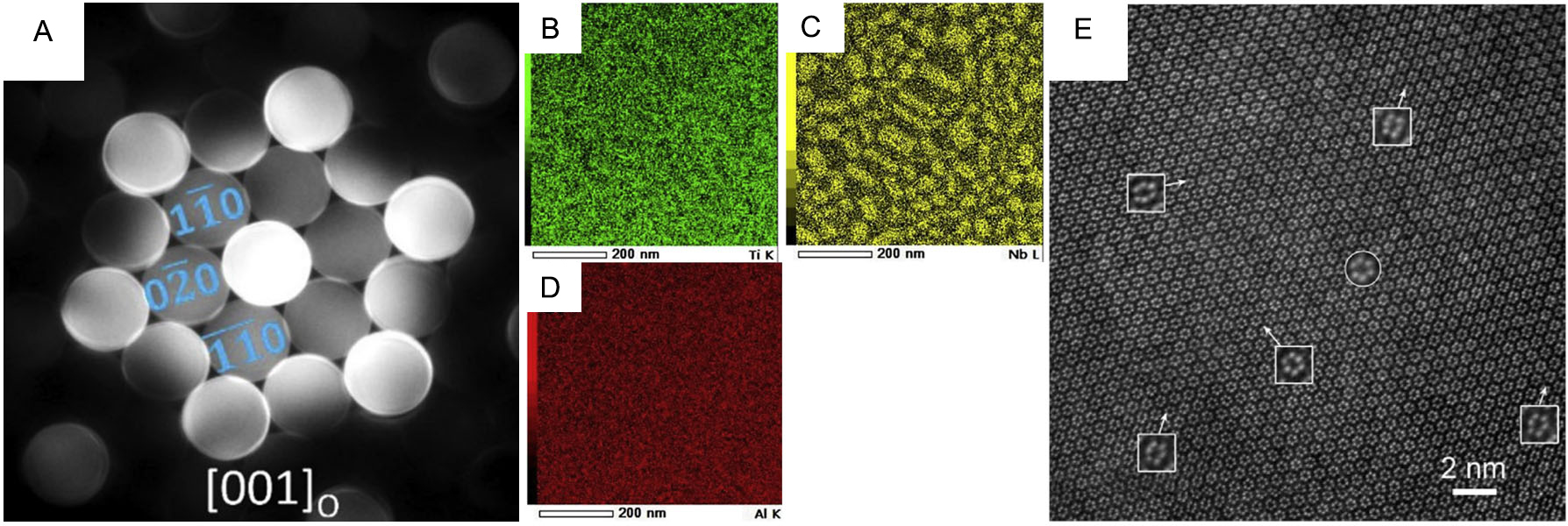
Figure 12. (A) CBED pattern of the O phase; (B-D) Atomic-resolution HAADF images showing the α2 and O phases along the
Crystallographic characteristics of O phase formation
Banerjee et al.[79] proposed that the hexagonal α2 and orthorhombic O phases should satisfy the OR as follows: [001]O//[0001]α2; [100]O//[11
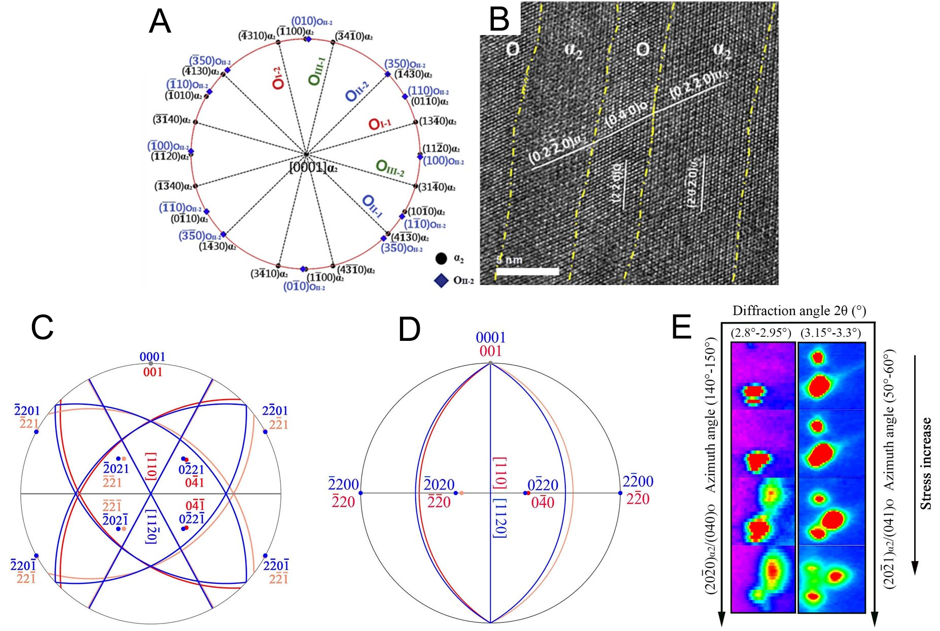
Figure 13. (A) [0001]α2 superimposed pole figures showing the lattice correspondence between the α2 and O phases, with the calculated habit planes being (
The α2→O structural transition involves lattice deformation (shuffling along three <11
Reversible stress-induced orthorhombic phase formation
The stress-induced orthorhombic and martensite phases formation from body-centered β phase or B2 phase has been extensively observed in NiTi and β-Ti alloys[96-101]. This transformation is highly reversible, enabling these alloys to withstand large elastic strains and thus exhibit promising practical applications. To elucidate the underlying mechanisms of this phase transition, in situ synchrotron or neutron diffraction techniques are essential for tracking the orthorhombic phase evolution under stress. In a Ni41Ti39Nb20 alloy, the orthorhombic B19’ phase was observed to gradually precipitate from the B2 phase during loading and a reverse transformation took place during unloading, as visible in Figure 14A[102]. However, some B19’ phase remains after unloading due to residual strain preserved from irreversible plastic deformation of Nb. Similarly, in a Ti-24Nb-4Zr-8Sn-0.1O single crystal, the diffraction spots of the β phase gradually split into those of the orthorhombic α” and δ phases during uniaxial tensile loading along the [110]β axis
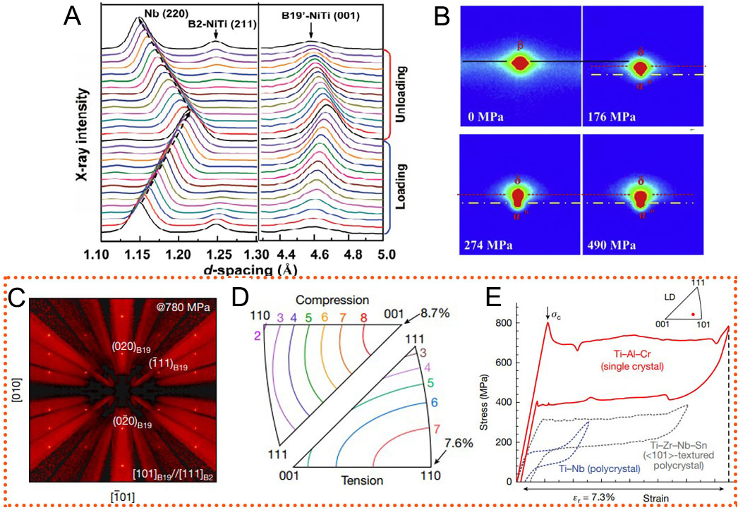
Figure 14. (A) Evolution of the diffraction peaks of (220)Nb, (211)B2 and (001)B19′ during the tension of a Ni41Ti39Nb20 alloy (Reproduced from Ref.[102][102]); (B) In a Ti-24Nb-4Zr-8Sn-0.1O single crystal, the (220)β spot gradually splits into diffraction spots belonging to the orthorhombic α” and δ phases. (Reproduced from Ref.[103][103]); A Ti75.25Al20Cr4.75 single crystal showing excellent superelasticity during tension: (C) B19 structure recorded at a stress of 780 MPa during in situ neutron diffraction; (D) calculated orientation dependence of transformation strain under tension and compression; (E) tensile loading-unloading stress-strain curves showing a large recovery strain of 7.3 %. (Reproduced from Ref.[104][104]).
Notably, a recent study on a specifically designed Ti3Al-based alloy (Ti75.25Al20Cr4.75) demonstrated exceptional superelasticity due to a reversible stress-induced orthorhombic phase transformation[104]. In situ neutron diffraction tension on near-<110> single crystals captured the diffraction patterns of the B2 and B19 structures (see Figure 14C) under different stress conditions. Furthermore, lattice deformation theory was employed to calculate the orientation-dependent transformation strain using the equation[105]:
Where x’ = Tx, x represents a given vector in the parent phase, x’ the corresponding vector in the precipitation phase, and T the lattice deformation matrix in the coordinates of the parent phase for the precipitate orthorhombic phase. For the B2 to B19 structural transition, normal strains along principal axes and shear strains are taken into account when calculating the lattice deformation matrix. For the α2 to orthorhombic O phase transformation, orthogonal strains along the [11
The superelasticity of shape memory alloys is closely associated with transformation strain and crystallographic texture. In the Ti-Zr-Nb-Sn alloy system, transformation strains show similar distributions across different alloy compositions, reaching a peak of approximately 7% along the [011]β direction[106]. However, recoverable elastic strains vary significantly due to differences in the spatial distribution of the β phase. For instance, the Ti-18Zr-15Nb alloy exhibits a weak {112}β<0
In a Ti-38Al-10Nb polycrystalline alloy, Liu et al.[37] reported a reversible stress-induced O phase transformation occurring at 800 °C and even 900 °C, temperatures exceeding the temperature range of the O phase. The O phase formation is strongly correlated with stress levels and evolves synchronously with internal stress accumulation in the α2 phase beyond a critical stress point. During the first loading, along with the rapid internal stress accumulation in the α2 phase at stresses above ~1,055 MPa, the α2 phase rapidly transforms into the O phase [Figure 15A and B]. During unloading and further holding, the O phase dissolves into the α2 matrix as internal stress relaxes [Figure 15C and D]. The α2→O phase transformation rapidly proceeds at stresses above ~1,220 MPa, where rapid internal stress accumulation takes place
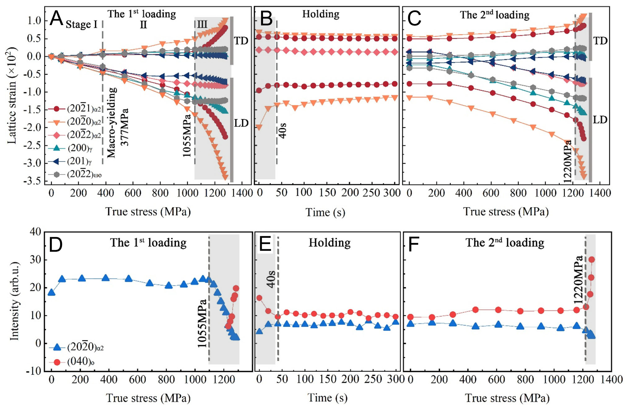
Figure 15. Lattice strain and intensity evolution in Ti-38Al-10Nb alloys subjected to double loading with an intermediate holding stage at 800 °C. (A) Lattice strain vs. true stress/holding time curves for α2 and γ reflections during the first loading; (B) Intensity vs. true stress curves for the (20
CONCLUSIONS
In situ diffraction techniques based on synchrotron X-ray and neutron sources are powerful tools for revealing the fundamental deformation mechanisms and phase evolution in γ-TiAl alloys. These
(1) In situ diffraction techniques reveal critical insights into deformation mechanisms in TiAl alloys
In γ-TiAl alloys, internal stress accumulation primarily originates from inhomogeneous deformation between the α2 and γ phases within the lamellar structure. Synchrotron X-ray and neutron diffraction studies demonstrate that the α2 phase, with its limited plasticity and strong deformation anisotropy, exhibits significant deformation incompatibility with the neighboring γ phase during loading. The distribution and morphology of the (α2+γ) lamellar structures strongly influence internal stress accumulation in the α2 phase due to their orientation-dependent deformation behavior. Texture evolution, including basal and transverse textures in the α2 phase, further interweaves with stress distribution between the α2 and γ phases. These coupled effects complicate the internal stress evolution, and in situ synchrotron X-ray and neutron diffraction offer effective means to address these challenges.
(2) Stress-induced O phase formation provides a promising approach for microstructural design
The O phase precipitation from the α2 phase emerges as a promising mechanism to improve the mechanical performance of TiAl alloys. Synchrotron X-ray combined with neutron diffraction has recognized the orthorhombic phase precipitating from the α2 phase as the O phase and distinguished its crystal structure. Coupled with TEM, the formation mechanism, involving minor lattice distortion and atomic shuffle, has been elucidated. In situ synchrotron experiments have confirmed the reversibility of this transformation under service-like conditions, particularly at 800 and 900 °C. Notably, this transformation has been observed primarily in high-Nb-containing TiAl alloys, where the Nb content promotes the formation and stability of the O phase. The α2→O transformation not only serves as an approach for accommodating internal stress but also introduces a new dimension for improving the ductility and fatigue performance of TiAl alloys, offering a promising pathway for microstructural design.
(3) Current challenges and further development for practical applications
Looking ahead, several key challenges continue to hinder a complete understanding and optimization of the deformation behavior and phase transformation mechanisms in TiAl alloys. These include uncovering the atomic-scale processes underlying phase transitions, accurately quantifying internal stress evolution under complex loading conditions, and establishing predictive links between microstructural features and macroscopic mechanical performance. Addressing these issues will require the combined use of synchrotron radiation and neutron diffraction alongside complementary techniques such as TEM, atom probe tomography (APT), and digital image correlation (DIC). Such integrated approaches will enable detailed, multiscale investigations into the relationships between structures and properties. Meanwhile, ongoing advancements in experimental infrastructure, including faster detectors, nanofocused beams, and four-dimensional scanning, will significantly enhance real-time characterization capabilities under realistic service conditions. Together, these developments are expected to advance both scientific understanding and the practical design of next-generation TiAl alloys for demanding aerospace and energy applications.
DECLARATIONS
Authors’ contributions
Writing original manuscript, reviewing and editing: Liu, X.
Reviewing and editing: Song, L.
Availability of data and materials
Not applicable.
Financial support and sponsorship
This work was supported by the National Natural Science Foundation of China (52471145), Key R&D Plan of Shaanxi Province (2024GX-YBXM-348), State Key Laboratory of Solidification Processing in NPU (2025-QZ-02), and Fundamental Research Funds for the Central Universities (D5000250265). Liu, X. gratefully acknowledges financial support from the China Scholarship Council (CSC).
Conflicts of interest
All authors declared that there are no conflicts of interest.
Ethical approval and consent to participate
Not applicable.
Consent for publication
Not applicable.
Copyright
© The Author(s) 2025.
REFERENCES
1. Clemens, H.; Mayer, S. Design, processing, microstructure, properties, and applications of advanced intermetallic TiAl alloys. Adv. Eng. Mater. 2013, 15, 191-215.
2. Appel, F.; Paul, J. D. H.; Oehring, M. Gamma titanium aluminide alloys: science and technology; John Wiley & Sons, 2011.
3. Appel, F.; Brossmann, U.; Christoph, U.; et al. Recent progress in the development of gamma titanium aluminide alloys. Adv. Eng. Mater. 2000, 2, 699-720.
4. Sun, L.; Wen, K.; Li, G.; et al. High-entropy alloys in catalysis: progress, challenges, and prospects. ACS. Mater. Au. 2024, 4, 547-56.
5. Kim, Y.; Kim, S. Advances in gammalloy materials-processes-application technology: successes, dilemmas, and future. JOM 2018, 70, 553-60.
6. Xu, X.; Lin, J.; Wang, Y.; Gao, J.; Lin, Z.; Chen, G. Effect of forging on microstructure and tensile properties of Ti-45Al-(8-9)Nb-(W,B,Y) alloy. J. Alloys. Compd. 2006, 414, 175-80.
7. Zhang, W.; Deevi, S.; Chen, G. On the origin of superior high strength of Ti-45Al-10Nb alloys. Intermetallics 2002, 10, 403-6.
8. Huang, H.; Ding, H.; Xu, X.; Chen, R.; Guo, J.; Fu, H. Phase transformation and microstructure evolution of a beta-solidified gamma-TiAl alloy. J. Alloys. Compd. 2021, 860, 158082.
9. Musi, M.; Graf, G.; Clemens, H.; Spoerk-erdely, P. Alloying elements in intermetallic γ-TiAl based alloys-a review on their influence on phase equilibria and phase transformations. Adv. Eng. Mater. 2024, 26, 2300610.
10. Appel, F.; Paul, J. D.; Staron, P.; et al. The effect of residual stresses and strain reversal on the fracture toughness of TiAl alloys. Mater. Sci. Eng. A. 2018, 709, 17-29.
11. Guo, F.; Ji, V.; François, M.; Zhang, Y. X-ray elastic constant determination and microstresses of α2 phase of a two-phase TiAl-based intermetallic alloy. Mater. Sci. Eng. A. 2003, 341, 182-8.
12. Zghal, S.; Naka, S.; Couret, A. A quantitative TEM analysis of the lamellar microstructure in TiAl based alloys. Acta. Mater. 1997, 45, 3005-15.
13. Zhu, H.; Seo, D.; Maruyama, K.; Au, P. Effect of microstructural stability on creep behavior of 47XD TiAl alloys with fine-grained fully lamellar structure. Scr. Mater. 2005, 52, 45-50.
14. Riemer, M.; Jentsch, H. G.; Biermann, H.; et al. The internal stress state in lamellar PST-crystals of the intermetallic alloy TiAl after compressive deformation. Intermetallics 1999, 7, 241-9.
15. Ma, Y.; Yang, J.; Liu, Z.; Chen, R. Deformation behavior of PST-TiAl bicrystals at 800 °C. Mater. Sci. Eng. A. 2024, 915, 147267.
16. Luo, Y.; Wang, Y.; Wang, L.; Liu, B.; Cao, Y.; Liu, Y. Effect of crystallographic texture on the anisotropy of fracture toughness in as-forged Ti-45Al-7Nb-0.4W-0.1B intermetallics. J. Alloys. Compd. 2025, 1014, 178672.
17. Cheng, L.; Zhu, B.; Yang, G.; Qiang, F.; Li, J. Insights into the abnormal flow softening of lamellar γ-TiAl alloys during hot-working: experimental analysis and numerical simulation. Mater. Sci. Eng. A. 2022, 852, 143695.
18. Inui, H.; Toda, Y.; Shirai, Y.; Yamaguchi, M. Low-temperature deformation of single crystals of a DO19 compound with an off-stoichiometric composition (Ti-36·5 at.% Al). Philos. Mag. A. 1994, 69, 1161-77.
19. Umakoshi, Y.; Nakano, T.; Takenaka, T.; Sumimoto, K.; Yamane, T. Orientation and temperature dependence of yield stress and slip geometry of Ti3Al and Ti3Al-V single crystals. Acta. Metall. Mater. 1993, 41, 1149-54.
20. Harada, S.; Yamaguchi, T.; Thirathipviwat, P.; Hasegawa, M. Lamellar orientation control of TiAl-based alloy by uniaxial compressive deformation at high-temperature in (α+β) two-phase region. J. Alloys. Compd. 2024, 1003, 175717.
21. Li, J.; Li, M.; Hu, L.; et al. Dynamic recrystallization, phase transformation and deformation mechanisms of a novel Ti-43Al-6Nb-1Mo-1Cr alloy during the isothermal deformation. Mater. Charact. 2023, 199, 112789.
22. Chen, X.; Tang, B.; Wei, B.; et al. Interaction between dynamic recrystallization and phase transformation of Ti-43Al-4Nb-1Mo-0.2B alloy during hot deformation. J. Mater. Sci. Technol. 2025, 214, 130-42.
23. Yang, J.; Wang, X.; Dong, C.; Fu, H. Thermomechanical instability and deformation behavior of βo(ω) phase region in a Ti-43Al-8Nb-0.2W-0.2B alloy under high-temperature rotary-bending fatigue. Int. J. Fatigue. 2022, 163, 106933.
24. Liu, Y.; Li, J.; Tang, B.; et al. Decomposition and phase transformation mechanisms of α2 lamellae in β-solidified γ-TiAl alloys. Acta. Mater. 2023, 242, 118492.
25. Liu, S.; Ding, H.; Chen, R.; Guo, J.; Fu, H. Evolution of rapidly grown cellular microstructure during heat treatment of TiAl-based intermetallic and its effect on micromechanical properties. Intermetallics 2021, 132, 107166.
26. Sun, T.; Liang, Y.; Yang, G.; et al. Twinning behavior and strengthening mechanism in a microalloyed TiAl alloy. Mater. Sci. Eng. A. 2023, 872, 144993.
28. Stark, A.; Bartels, A.; Clemens, H.; Schimansky, F. On the formation of ordered ω-phase in high Nb containing γ-TiAl based alloys. Adv. Eng. Mater. 2008, 10, 929-34.
29. Liang, Z.; Xiao, S.; Chi, D.; et al. Compressive creep behavior of high Nb containing TiAl alloy: dynamic recrystallization and phase transformation. Intermetallics 2023, 163, 108067.
30. Cao, G.; Russell, A.; Oertel, C.; Skrotzki, W. Microstructural evolution of TiAl-based alloys deformed by high-pressure torsion. Acta. Mater. 2015, 98, 103-12.
31. Niu, H.; Chen, X.; Chen, Y.; Zhao, S.; Liu, G.; Zhang, D. Microstructural stability, phase transformation and mechanical properties of a fully-lamellar microstructure of a Mo-modified high-Nb γ-TiAl alloy. Mater. Sci. Eng. A. 2020, 784, 139313.
32. Banerjee, D. Deformation of the O and α2 phases in the Ti-Al-Nb system. Philos. Mag. A. 1995, 72, 1559-87.
33. Gabrisch, H.; Lorenz, U.; Pyczak, F.; Rackel, M.; Stark, A. Morphology and stability of orthorhombic and hexagonal phases in a lamellar γ-Ti-42Al-8.5Nb alloy-A transmission electron microscopy study. Acta. Mater. 2017, 135, 304-13.
34. Rackel, M. W.; Stark, A.; Gabrisch, H.; Pyczak, F. Screening for O phase in advanced γ-TiAl alloys. Intermetallics 2021, 131, 107086.
35. Rackel, M. W.; Stark, A.; Gabrisch, H.; Schell, N.; Schreyer, A.; Pyczak, F. Orthorhombic phase formation in a Nb-rich γ-TiAl based alloy-an in situ synchrotron radiation investigation. Acta. Mater. 2016, 121, 343-51.
36. Dai, C.; Yang, Z.; Sun, J.; Lu, S.; Vitos, L. Composition and temperature dependence of α2 phase decomposition in high Nb-containing lamellar γ-TiAl alloys: experiments and first-principles calculations. Acta. Materialia. 2021, 221, 117419.
37. Liu, X.; Song, L.; Pyczak, F.; et al. Stress-induced orthorhombic O phase in TiAl alloys. Acta. Mater. 2025, 286, 120751.
38. Muraleedharan, K.; Nandy, T.; Banerjee, D.; Lele, S. Phase stability and ordering behaviour of the O phase in Ti Al Nb alloys. Intermetallics 1995, 3, 187-99.
39. Dye, D.; Stone, H.; Reed, R. Intergranular and interphase microstresses. Curr. Opin. Solid. State. Mater. Sci. 2001, 5, 31-7.
40. Pang, J.; Holden, T.; Wright, J.; Mason, T. The generation of intergranular strains in 309H stainless steel under uniaxial loading. Acta. Mater. 2000, 48, 1131-40.
41. Clausen, B.; Lorentzen, T.; Leffers, T. Self-consistent modelling of the plastic deformation of f.c.c. polycrystals and its implications for diffraction measurements of internal stresses. Acta. Mater. 1998, 46, 3087-98.
42. Cui, Y.; Li, C.; Zhang, C.; et al. Effect of initial microstructure on the micromechanical behavior of Ti-55531 titanium alloy investigated by in-situ high-energy X-ray diffraction. Mater. Sci. Eng. A. 2020, 772, 138806.
43. Sedmák, P.; Šittner, P.; Pilch, J.; Curfs, C. Instability of cyclic superelastic deformation of NiTi investigated by synchrotron X-ray diffraction. Acta. Mater. 2015, 94, 257-70.
44. Ma, L.; Wang, L.; Nie, Z.; et al. Reversible deformation-induced martensitic transformation in Al0.6CoCrFeNi high-entropy alloy investigated by in situ synchrotron-based high-energy X-ray diffraction. Acta. Mater. 2017, 128, 12-21.
45. Young, M.; Almer, J.; Daymond, M.; Haeffner, D.; Dunand, D. Load partitioning between ferrite and cementite during elasto-plastic deformation of an ultrahigh-carbon steel. Acta. Mater. 2007, 55, 1999-2011.
46. Wang, Y. D.; Wang, X.; Stoica, A. D.; Richardson, J. W.; Lin, Peng. R. Determination of the stress orientation distribution function using pulsed neutron sources. J. Appl. Cryst. 2003, 36, 14-22.
47. Bernier, J. V.; Miller, M. P. A direct method for the determination of the mean orientation-dependent elastic strains and stresses in polycrystalline materials from strain pole figures. J. Appl. Cryst. 2006, 39, 358-68.
48. Mcnelis, K. P.; Dawson, P. R.; Miller, M. P. A two-scale methodology for determining the residual stresses in polycrystalline solids using high energy X-ray diffraction data. J. Mech. Phys. Solids. 2013, 61, 428-49.
49. Miller, M.; Park, J.; Dawson, P.; Han, T. Measuring and modeling distributions of stress state in deforming polycrystals. Acta. Mater. 2008, 56, 3927-39.
50. Alvarez M, Buioli C, Santisteban J, Vizcaino P. Evolution of texture and intergranular stresses of αZr and minority phases in Zr-2.5Nb pressure tube through synchrotron X-ray diffraction. Acta. Mater. 2024, 271, 119802.
51. Wang, Y. D.; Peng, R. L.; Zeng, X.; Mcgreevy, R. Stress-orientation distribution function (SODF)-description, symmetry and determination. MSF 2000, 347-9, 66-73.
52. Wang, Y.; Peng, R. L.; Mcgreevy, R. A novel method for constructing the mean field of grain-orientation-dependent residual stress. Philos. Mag. Lett. 2001, 81, 153-63.
53. Wang, Y.; Lin, Peng. R.; Wang, X.; Mcgreevy, R. Grain-orientation-dependent residual stress and the effect of annealing in cold-rolled stainless steel. Acta. Mater. 2002, 50, 1717-34.
54. Miller, M. P.; Bernier, J. V.; Park, J.; Kazimirov, A. Experimental measurement of lattice strain pole figures using synchrotron x rays. Rev. Sci. Instrum. 2005, 76, 113903.
55. Luo, S.; Khong, J. C.; Huang, S.; Yang, G.; Mi, J. Revealing in situ stress-induced short- and medium-range atomic structure evolution in a multicomponent metallic glassy alloy. Acta. Mater. 2024, 272, 119917.
56. Zhang, X.; Ma, L.; Xue, Y.; et al. Temperature dependence of micro-deformation behavior of the porous tungsten/Zr-based metallic glass composite. J. Non-Cryst. Solids. 2016, 436, 9-17.
57. Cheng, S.; Wang, Y.; Choo, H.; et al. An assessment of the contributing factors to the superior properties of a nanostructured steel using in situ high-energy X-ray diffraction. Acta. Mater. 2010, 58, 2419-29.
58. Dieter, G. E.; Bacon, D. Mechanical metallurgy; New York: McGraw-hill, 1986. https://archive.org/details/mechanicalmetall00diet/page/n11/mode/2up (accessed 2025-09-19).
59. Appel, F.; Clemens, H.; Fischer, F. Modeling concepts for intermetallic titanium aluminides. Prog. Mater. Sci. 2016, 81, 55-124.
60. Song, L.; Appel, F.; Liu, W.; Pyczak, F.; Zhang, T. {1 01} tension twins and {1 01}-{2 01}/{2 01}-{1 01} double twins in the D019 ordered hexagonal α2-Ti3Al phase. Acta. Materialia. 2023, 260, 119335.
61. Erdely, P.; Staron, P.; Maawad, E.; Schell, N.; Clemens, H.; Mayer, S. Lattice and phase strain evolution during tensile loading of an intermetallic, multi-phase γ-TiAl based alloy. Acta. Mater. 2018, 158, 193-205.
62. Ding, J.; Zhang, M.; Ye, T.; et al. Microstructure stability and micro-mechanical behavior of as-cast gamma-TiAl alloy during high-temperature low cycle fatigue. Acta. Matera. 2018, 145, 504-15.
63. Wimler, D.; Lindemann, J.; Kremmer, T.; Clemens, H.; Mayer, S. Microstructure and mechanical properties of novel TiAl alloys tailored via phase and precipitate morphology. Intermetallics 2021, 138, 107316.
64. Todai, M.; Nakano, T.; Liu, T.; et al. Effect of building direction on the microstructure and tensile properties of Ti-48Al-2Cr-2Nb alloy additively manufactured by electron beam melting. Addit. Manuf. 2017, 13, 61-70.
65. Liu, X.; Song, L.; Stark, A.; Pyczak, F.; Zhang, T. In-situ synchrotron high energy X-ray diffraction study on the internal strain evolution of D019-α2 phase during high-temperature compression and subsequent annealing in a TiAl alloy. J. Mater. Sci. Technol. 2023, 163, 212-22.
66. Liu, X.; Song, L.; Stark, A.; Pyczak, F.; Zhang, T. In-situ synchrotron high energy X-ray diffraction study on the deformation mechanisms of D019-α2 phase during high-temperature compression in a TiAl alloy. J. Mater. Res. Technol. 2024, 33, 5850-62.
67. Blackburn, M. J.; Jaffee, R. I.; Promisel, N. E. The Science, technology, and application of titanium: proceedings; Pergamon Press, Oxford, 1970; p 633. https://books.google.com/books/about/The_Science_Technology_and_Application_o.html?id=pV98AAAAIAAJ (accessed 2025-09-18).
68. Selvarajou, B.; Jhon, M. H.; Ramanujan, R.; Quek, S. S. Temperature dependent anisotropic mechanical behavior of TiAl based alloys. Int. J. Plast. 2022, 152, 103175.
69. Stark, A.; Bartels, A.; Clemens, H.; Kremmer, S.; Schimansky, F.; Gerling, R. Microstructure and texture formation during near conventional forging of an intermetallic Ti-45Al-5Nb alloy. Adv. Eng. Mater. 2009, 11, 976-81.
70. Stark, A.; Bartels, A.; Gerling, R.; Schimansky, F.; Clemens, H. Microstructure and texture formation during hot rolling of niobium-rich γ TiAl alloys with different carbon contents. Adv. Eng. Mater. 2006, 8, 1101-8.
71. Erdely, P.; Staron, P.; Maawad, E.; et al. Design and control of microstructure and texture by thermomechanical processing of a multi-phase TiAl alloy. Mater. Des. 2017, 131, 286-96.
72. Erdely, P.; Staron, P.; Maawad, E.; et al. Effect of hot rolling and primary annealing on the microstructure and texture of a β-stabilised γ-TiAl based alloy. Acta. Mater. 2017, 126, 145-53.
73. Jia, M.; Qiang, F.; Yu, Y.; Wang, Y.; Li, J.; Kou, H. Tailoring lamellar orientation and tensile properties of TNM alloy via extrusion. J. Mater. Res. Technol. 2024, 28, 363-70.
74. Schillinger, W.; Bartels, A.; Gerling, R.; Schimansky, F.; Clemens, H. Texture evolution of the γ- and the α/α2-phase during hot rolling of γ-TiAl based alloys. Intermetallics 2006, 14, 336-47.
75. Stark, A.; Schwaighofer, E.; Mayer, S.; et al.
76. Wagner, F.; Bozzolo, N.; Van, Landuyt. O.; Grosdidier, T. Evolution of recrystallisation texture and microstructure in low alloyed titanium sheets. Acta. Mater. 2002, 50, 1245-59.
77. Wang, Z.; Wu, S.; Kang, G.; et al. In-situ synchrotron X-ray tomography investigation of damage mechanism of an extruded magnesium alloy in uniaxial low-cycle fatigue with ratchetting. Acta. Mater. 2021, 211, 116881.
78. Li, T.; Zheng, J.; Gupta, M.; He, L.; Xia, L.; Jiang, B. Quantitative investigation on the {10-12} twinning-detwinning behavior and twinning transfer of an extruded Mg-2.8Y sheet during compression-tension loading via quasi-in-situ EBSD observation. J. Mater. Res. Technol. 2023, 26, 2957-74.
79. Banerjee, D.; Gogia, A.; Nandi, T.; Joshi, V. A new ordered orthorhombic phase in a Ti3Al Nb alloy. Acta. Metall. 1988, 36, 871-82.
81. Bendersky, L.; Boettinger, W. Phase transformations in the (Ti, Nb)3 Al section of the Ti Al Nb system-II. experimental TEM study of microstructures. Acta. Acta. Metall. Mater. 1994, 42, 2337-52.
82. Appel, F.; Oehring, M.; Paul, J. Nano-scale design of TiAl alloys based on β-phase decomposition. Adv. Eng. Mater. 2006, 8, 371-6.
83. Appel, F.; Oehring, M.; Paul, J. A novel in situ composite structure in TiAl alloys. Mater. Sci. Eng. A. 2008, 493, 232-6.
84. Appel, F.; Paul, J.; Oehring, M. Phase transformations during creep of a multiphase TiAl-based alloy with a modulated microstructure. Mater. Sci. Eng. A. 2009, 510-1, 342-9.
85. Song, L.; Xu, X.; You, L.; Liang, Y.; Lin, J. B19 phase in Ti-45Al-8.5Nb-0.2W-0.2B-0.02Y alloy. J. Alloys. Compd. 2015, 618, 305-10.
86. Musi, M.; Erdely, P.; Rashkova, B.; et al. Evidence of an orthorhombic transition phase in a Ti-44Al-3Mo (at.%) alloy using in situ synchrotron diffraction and transmission electron microscopy. Mater. Charact. 2019, 147, 398-405.
87. Bendersky, L.; Roytburd, A.; Boettinger, W. Phase transformations in the (Ti, Al)3 Nb section of the Ti Al Nb system-I. microstructural predictions based on a subgroup relation between phases. Acta. Metall. Mater. 1994, 42, 2323-35.
88. Ren, G.; Sun, J. High-resolution electron microscopy characterization of modulated structure in high Nb-containing lamellar γ-TiAl alloy. Acta. Mater. 2018, 144, 516-23.
89. Ren, G.; Dai, C.; Mei, W.; Sun, J.; Lu, S.; Vitos, L. Formation and temporal evolution of modulated structure in high Nb-containing lamellar γ-TiAl alloy. Acta. Mater. 2019, 165, 215-27.
90. Xu, S.; Reid, M.; Lin, J.; et al. The crystal structure and transformations of the omicron phase Ο in the Ti-Al-Nb system and on the ambiguity of its subvariants Ο1 and Ο2. Scr. Mater. 2022, 219, 114841.
91. Mozer, B.; Bendersky, L.; Boettinger, W.; Rowe, R. Neutron powder diffraction study of the orthorhombic Ti2AlNb phase. Scr. Metall. Mater. 1990, 24, 2363-8.
92. Gabrisch, H.; Janovská, M.; Rackel, M. W.; Pyczak, F.; Stark, A. Impact of microstructure on elastic properties in the alloy Ti-42Al-8.5Nb. J. Alloys. Compd. 2023, 932, 167578.
93. Muraleedharan, K.; Banerjee, D.; Banerjee, S.; Lele, S. The α2-to-O transformation in Ti-Al-Nb alloys. Philos. Mag. A. 1995, 71, 1011-36.
94. Wen, Y.; Wang, Y.; Bendersky, L.; Chen, L. Microstructural evolution during the α2→α2+O transformation in Ti-Al-Nb alloys: phase-field simulation and experimental validation. Acta. Mater. 2000, 48, 4125-35.
95. Wen, Y.; Wang, Y.; Chen, L. Effect of elastic interaction on the formation of a complex multi-domain microstructural pattern during a coherent hexagonal to orthorhombic transformation. Acta. Mater. 1999, 47, 4375-86.
96. Feng, B.; Kong, X.; Hao, S.; et al. In-situ synchrotron high energy X-ray diffraction study of micro-mechanical behaviour of R phase reorientation in nanocrystalline NiTi alloy. Acta. Mater. 2020, 194, 565-76.
97. Xu, K.; Luo, J.; Li, C.; et al. Mechanisms of stress-induced martensitic transformation and transformation-induced plasticity in NiTi shape memory alloy related to superelastic stability. Scr. Mater. 2022, 217, 114775.
98. Grabec, T.; Sedlák, P.; Zoubková, K.; et al. Evolution of elastic constants of the NiTi shape memory alloy during a stress-induced martensitic transformation. Acta. Mater. 2021, 208, 116718.
99. Tyc, O.; Iaparova, E.; Molnárová, O.; Heller, L.; Šittner, P. Stress induced martensitic transformation in NiTi at elevated temperatures: Martensite variant microstructures, recoverable strains and plastic strains. Acta. Mater. 2024, 279, 120287.
100. Chen, Y.; Klinger, M.; Duchoň, J.; Šittner, P. Modulated martensite in NiTi shape memory alloy exposed to high stress at high temperatures. Acta. Mater. 2023, 258, 119250.
101. Iaparova, E.; Heller, L.; Tyc, O.; Sittner, P. Thermally induced reorientation and plastic deformation of B19’ monoclinic martensite in nanocrystalline NiTi wires. Acta. Mater. 2023, 242, 118477.
102. Hao, S.; Cui, L.; Jiang, D.; et al. A transforming metal nanocomposite with large elastic strain, low modulus, and high strength. Science 2013, 339, 1191-4.
103. Liu, J.; Wang, Y.; Hao, Y.; et al. High-energy X-ray diffuse scattering studies on deformation-induced spatially confined martensitic transformations in multifunctional Ti-24Nb-4Zr-8Sn alloy. Acta. Mater. 2014, 81, 476-86.
104. Song, Y.; Xu, S.; Sato, S.; et al. A lightweight shape-memory alloy with superior temperature-fluctuation resistance. Nature 2025, 638, 965-71.
105. Otsuka, K.; Ren, X. Physical metallurgy of Ti-Ni-based shape memory alloys. Prog. Mater. Sci. 2005, 50, 511-678.
106. Li, S.; Nam, T. Superelasticity and tensile strength of Ti-Zr-Nb-Sn alloys with high Zr content for biomedical applications. Intermetallics 2019, 112, 106545.
107. Fu, J.; Yamamoto, A.; Kim, H. Y.; Hosoda, H.; Miyazaki, S. Novel Ti-base superelastic alloys with large recovery strain and excellent biocompatibility. Acta. Biomater. 2015, 17, 56-67.
Cite This Article
How to Cite
Download Citation
Export Citation File:
Type of Import
Tips on Downloading Citation
Citation Manager File Format
Type of Import
Direct Import: When the Direct Import option is selected (the default state), a dialogue box will give you the option to Save or Open the downloaded citation data. Choosing Open will either launch your citation manager or give you a choice of applications with which to use the metadata. The Save option saves the file locally for later use.
Indirect Import: When the Indirect Import option is selected, the metadata is displayed and may be copied and pasted as needed.
About This Article
Special Issue
Copyright

Data & Comments
Data
0


Comments
Comments must be written in English. Spam, offensive content, impersonation, and private information will not be permitted. If any comment is reported and identified as inappropriate content by OAE staff, the comment will be removed without notice. If you have any queries or need any help, please contact us at [email protected].