


Evidence of shear stress component in Lüders front based on an in-situ synchrotron high-energy X-ray diffraction experiment
 0
0 
Abstract
The formation and propagation of
Keywords
INTRODUCTION
Medium-Mn steels (typically containing 3-12 wt.% Mn) have attracted considerable attention from both academic researchers and the automotive industry owing to their outstanding combination of mechanical properties and cost-effectiveness in production[1-6]. Exceptional performance has been achieved in medium-Mn steels through meticulous composition design and optimized manufacturing processes such as hot and/or cold rolling, intercritical annealing, and low-temperature tempering, realizing impressive tensile strengths of up to 1,500 MPa, coupled with remarkable ductility exceeding 40%[7-10]. These attributes make the steel highly appealing for applications requiring strength and formability, particularly in automotive structures.
Despite the advantages mentioned above, the appearance of
The study of
Besides the works on the dynamics of
This work employed the in-situ synchrotron HE-XRD technique to investigate the
MATERIALS AND METHODS
Materials preparation
The experimental TRIP steel had a nominal composition (in mass%) of Fe-0.1C-10Mn-2Al, with the detailed measurement data provided in Table 1. Steel ingots were initially cast within a vacuum furnace to ensure high purity. Subsequently, the resulting 20-mm-thick plates underwent homogenization at 1,200 °C for 1 h to achieve a uniform microstructure, followed by hot rolling in the temperature range of
Chemical composition of the experimental Fe-0.1C-10Mn-2Al steel (mass%)[37]
| C | Mn | Al | Si | Fe |
| 0.12 | 10.16 | 1.87 | 0.05 | Bal |
Microstructure characterization
The microstructure was characterized with a field emission scanning electron microscope (Zeiss Supra55) furnished with an Oxford electron backscatter diffraction (EBSD) detector using a step size of 35 nm. The specimen destined for EBSD characterization was initially ground successively with 150-grit to 3000-grit SiC papers, then polished using a diamond polishing compound with a particle size of 2.5 μm. Finally, it was subjected to electropolishing in a solution where the volume ratio of HClO4 to C2H6O is 1:9 under a direct voltage of 20 V at room temperature. The scanning electron microscopy (SEM) specimens were etched in a 4% nitric acid solution after completing the aforementioned polishing procedures. Once the etching was complete, the specimens were immediately rinsed with ethanol to remove any residual etching solution from the surface.
The deformation behavior of the experimental steel was investigated by using the in-situ synchrotron-based HE-XRD technique at the 11-ID-C beamline of the Advanced Photon Source, Argonne National Laboratory (APS, ANL) in the US. The microstructure evolution and measured lattice strain changes of the specimen under uniaxial tensile loading were studied using a monochromatic X-ray beam with an energy of
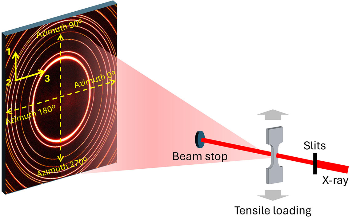
Figure 1. Schematic of in-situ HE-XRD loading experiment.
The experimental coordination system (axes 1-2-3) and azimuthal angle definition of the Debye rings are indicated in yellow in Figure 1. Cross-sectional data, where the scattering vector was parallel to various azimuths, were integrated to calculate the (azimuthal) measured lattice strain (to be explained later in the same paragraph) of various phases. The measured lattice strain, εhkl, was determined based on the relative change in the lattice plane spacing corresponding to the crystallographic plane (hkl), expressed as
where d0hkl and dhkl denote the lattice spacings before and after applying stress at the test temperature, respectively. Note that the term “measured lattice strain” is used in this context to distinguish it from the commonly used “lattice strain”. In HE-XRD experiments, lattice strain calculations typically rely on certain assumptions, the most critical of which is that the irradiated volume is homogeneous regarding both microstructure and stress state. When this assumption is strictly met, the lattice strain calculated using Equation 1 corresponds to the true physical value, representing the elastic strain within the irradiated volume along the diffraction vector direction. However, due to the propagative nature of the
RESULTS AND DISCUSSION
Figure 2A displays the 2D XRD pattern of the initial medium-Mn TRIP steel, recorded over the full azimuthal angle range of 0° to 360°. The experimental steel exhibits an ultrafine-grained duplex microstructure comprising face-centered cubic (FCC) austenite (γ) and body-centered cubic (BCC) ferrite
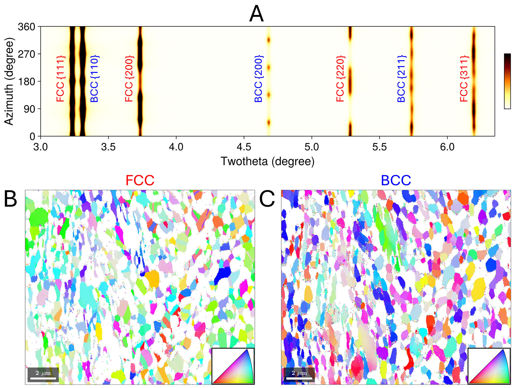
Figure 2. (A) 2D XRD pattern along the full azimuthal angle from 0° to 360° for the investigated medium-Mn TRIP steel of the initial state. Orientation images with inverse pole figure coloring along the azimuth 0° (axis-3 in Figure 1) for FCC γ phase (B) and BCC α phase (C). (For interpretation of the references to color in this figure legend, the reader is referred to the web version of this article).
Figure 3 illustrates the DIC strain field and SEM micrographs of three distinct microstructural regions. Samples used for the SEM characterizations were taken from a specimen deformed to a tensile strain of 0.055. This strain level corresponds to the point at which the
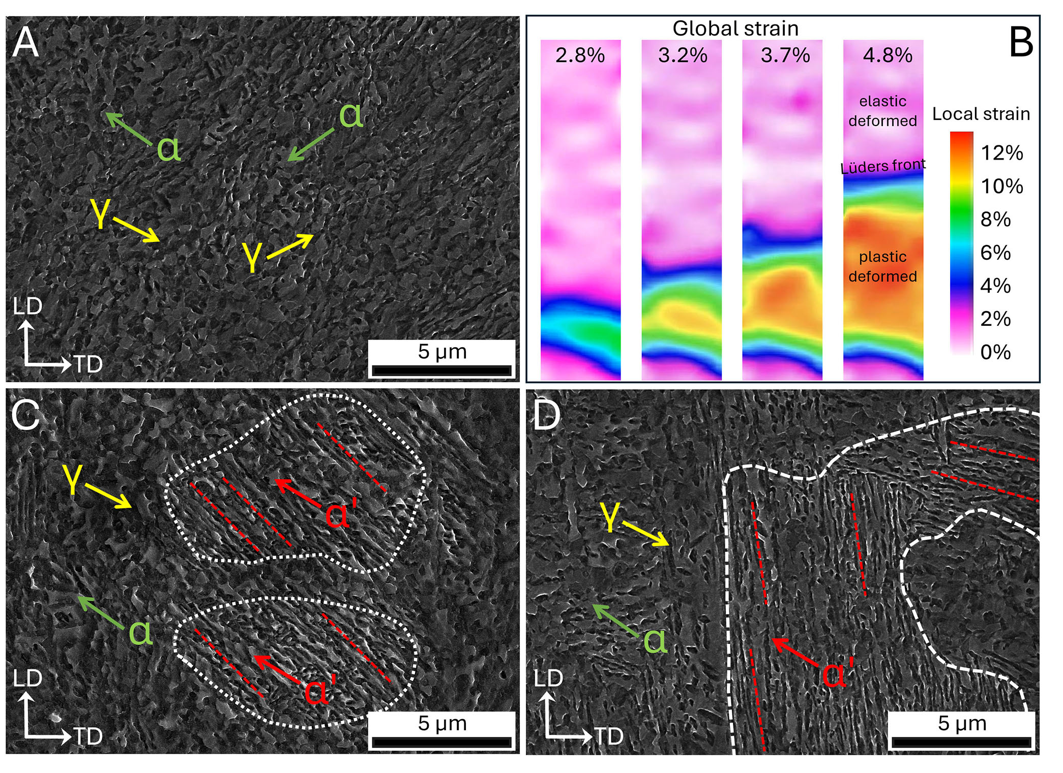
Figure 3. DIC strain field and SEM micrographs. (A) SEM micrograph of the undeformed region. (B) DIC strain field and localized strain. (C) SEM micrograph of the
Figure 4 presents the engineering stress-strain curve obtained from the in-situ HE-XRD loading experiment of the investigated medium-Mn TRIP steel at room temperature. A general analysis of the phase transformation that occurred during the experiment can be found in[37]. Here, we focus on the microstructural and stress states of the migrating
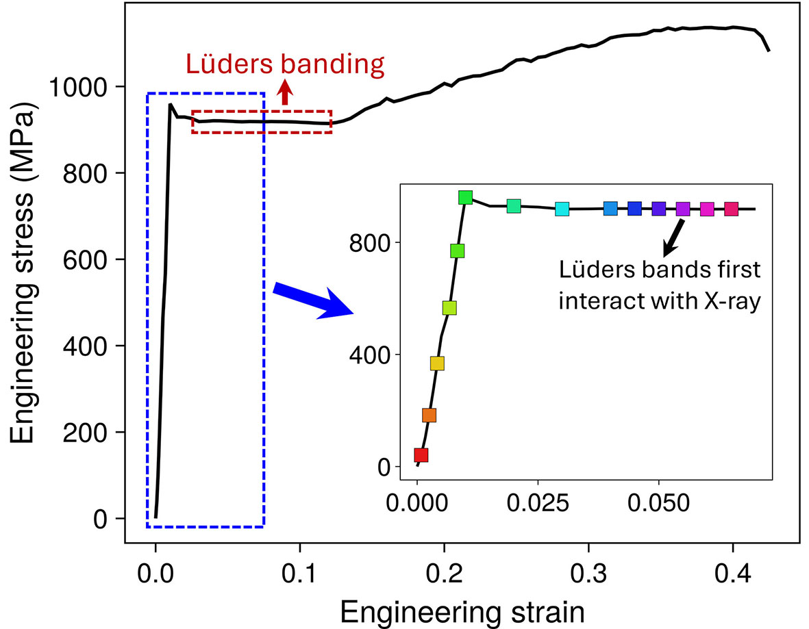
Figure 4. Engineering stress-strain curve of the medium-Mn TRIP steel during in-situ HE-XRD loading experiment[37]. The inset magnifies the early deformation stage, highlighting the selected strain points. (For interpretation of the references to color in this figure legend, the reader is referred to the web version of this article).
The azimuth-dependent variation of integrated diffraction intensities for the two phases as
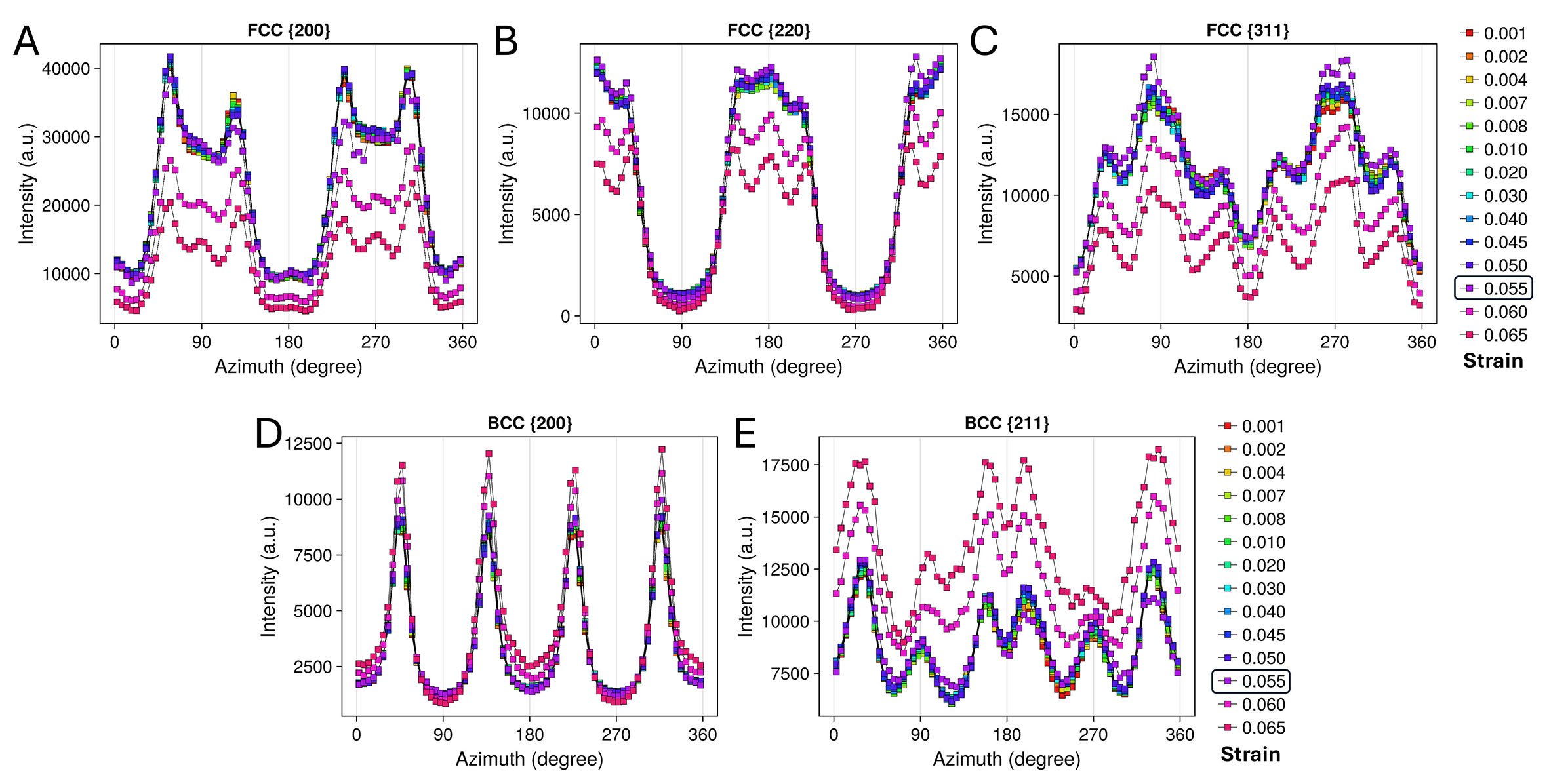
Figure 5. Integrated diffraction intensity as a function of azimuth for the FCC γ and BCC α/α’ phases from a series of strain points. (A) FCC {200}. (B) FCC {220}. (C) FCC {311}. (D) BCC {200}. (E) BCC {211}. The strain-point color coding is consistent with that used in the inset of Figure 4. The boxed strain of 0.055 corresponds to the point at which the
The variations in the peak full width at half maximum (FWHM) for the selected strain points are shown in Figure 6, based on which the degree of plastic deformation can be evaluated. Unlike in intensity, the FWHM curves for the critical 0.055 strain point exhibit a noticeable increase across all peaks compared to earlier strain points. However, this increase remains significantly lower than that observed at the 0.06 strain point, which corresponds to the state after complete
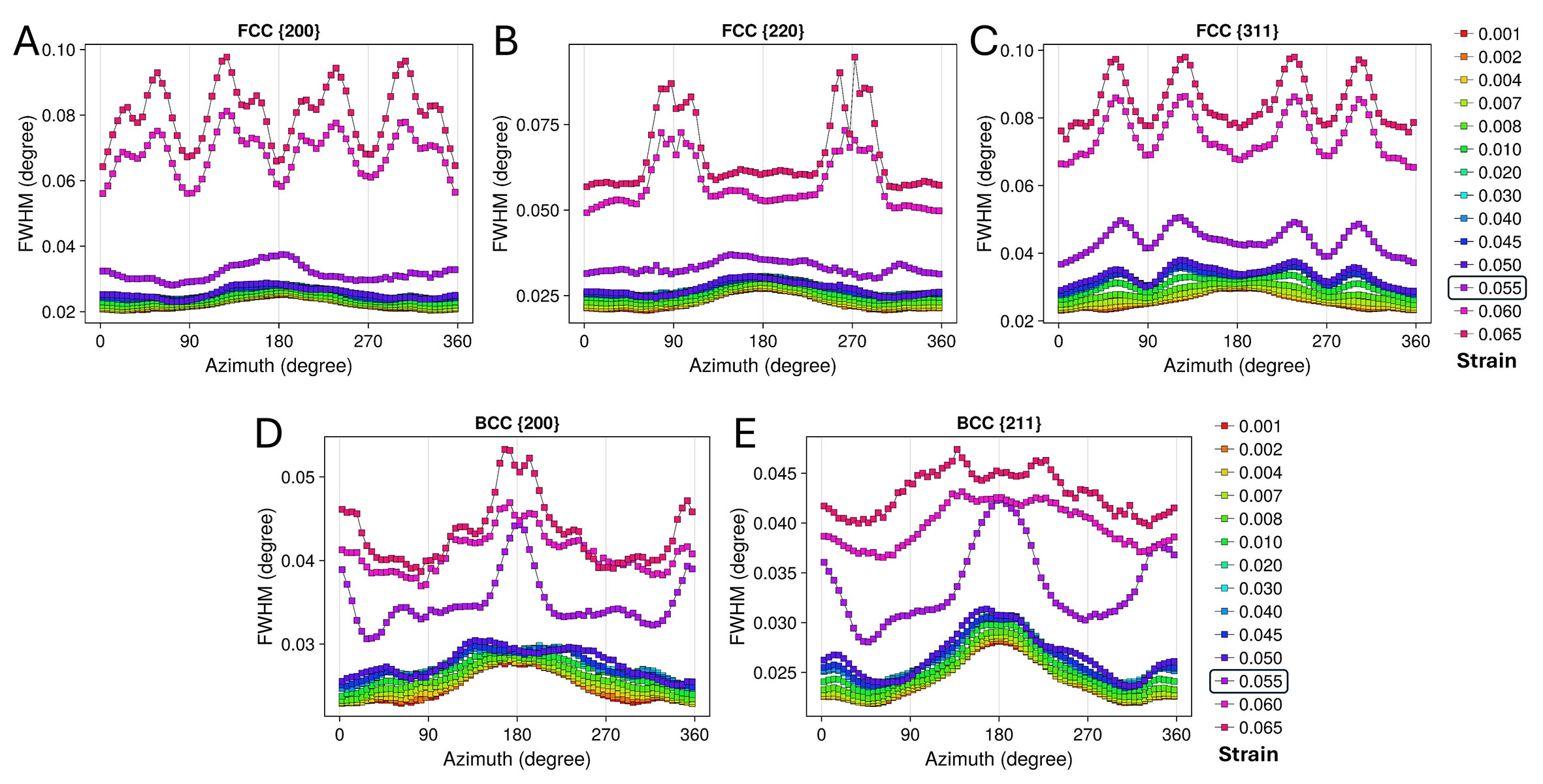
Figure 6. The peak full width at half maximum as a function of azimuth for the FCC γ and BCC α/α’ phases from a series of strain points. (A) FCC {200}. (B) FCC {220}. (C) FCC {311}. (D) BCC {200}.(E) BCC {211}. The strain-point color coding is consistent with that used in the inset of Figure 4. The boxed strain of 0.055 corresponds to the point at which the
Based on the above analysis, the critical 0.055 strain point can be considered representative of the
Figures 7 and 8 illustrate the azimuth-dependent variations of measured lattice strains for crystallographic planes of the two phases at different applied strain levels (aligned to strain points of Figures 4-6). The curves prior to the critical strain point of 0.055 exhibit typical cosine-function-like shapes with the measured lattice strain values steadily increasing as deformation progresses [Figure 7A-C, Figure 8A and B]. After complete
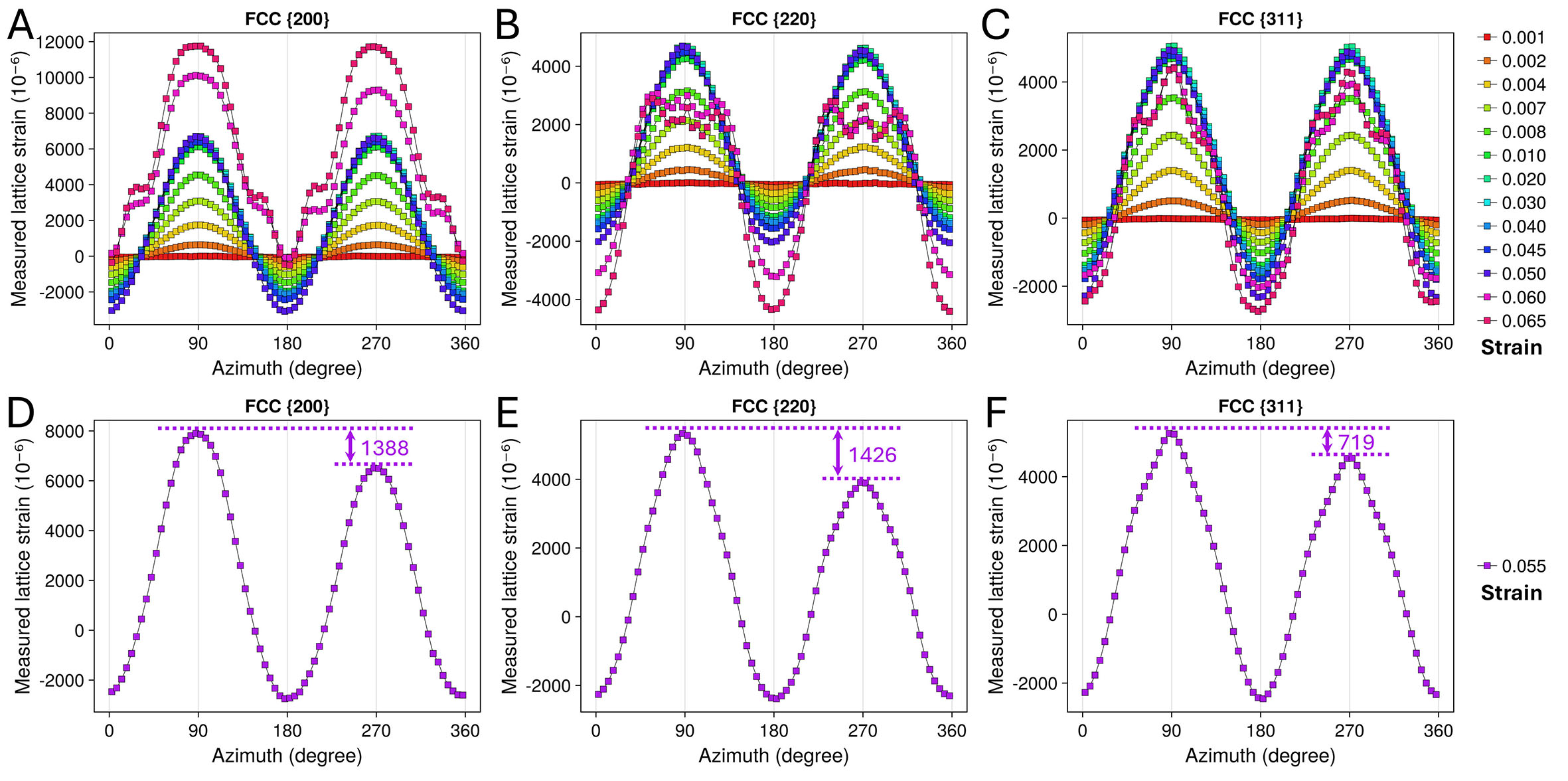
Figure 7. Measured lattice strain as a function of azimuth for the FCC γ phase. (A-C) Lattice strain data from a series of strain points beside 0.055. (D-F) Lattice strain data from the strain point of 0.055, where the
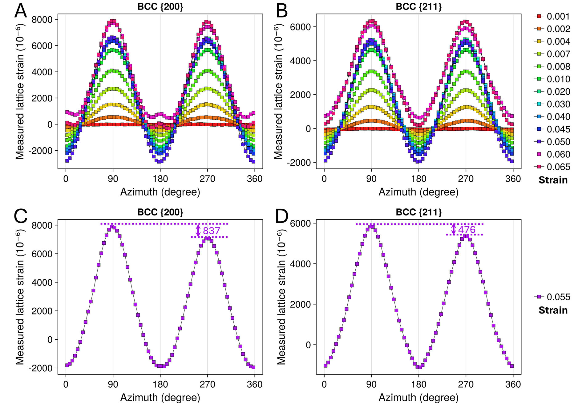
Figure 8. Measured lattice strain as a function of azimuth for the BCC α/α’ phase. (A and B) Lattice strain data from a series of strain points beside 0.055. (C and D) Lattice strain data from the strain point of 0.055, where the
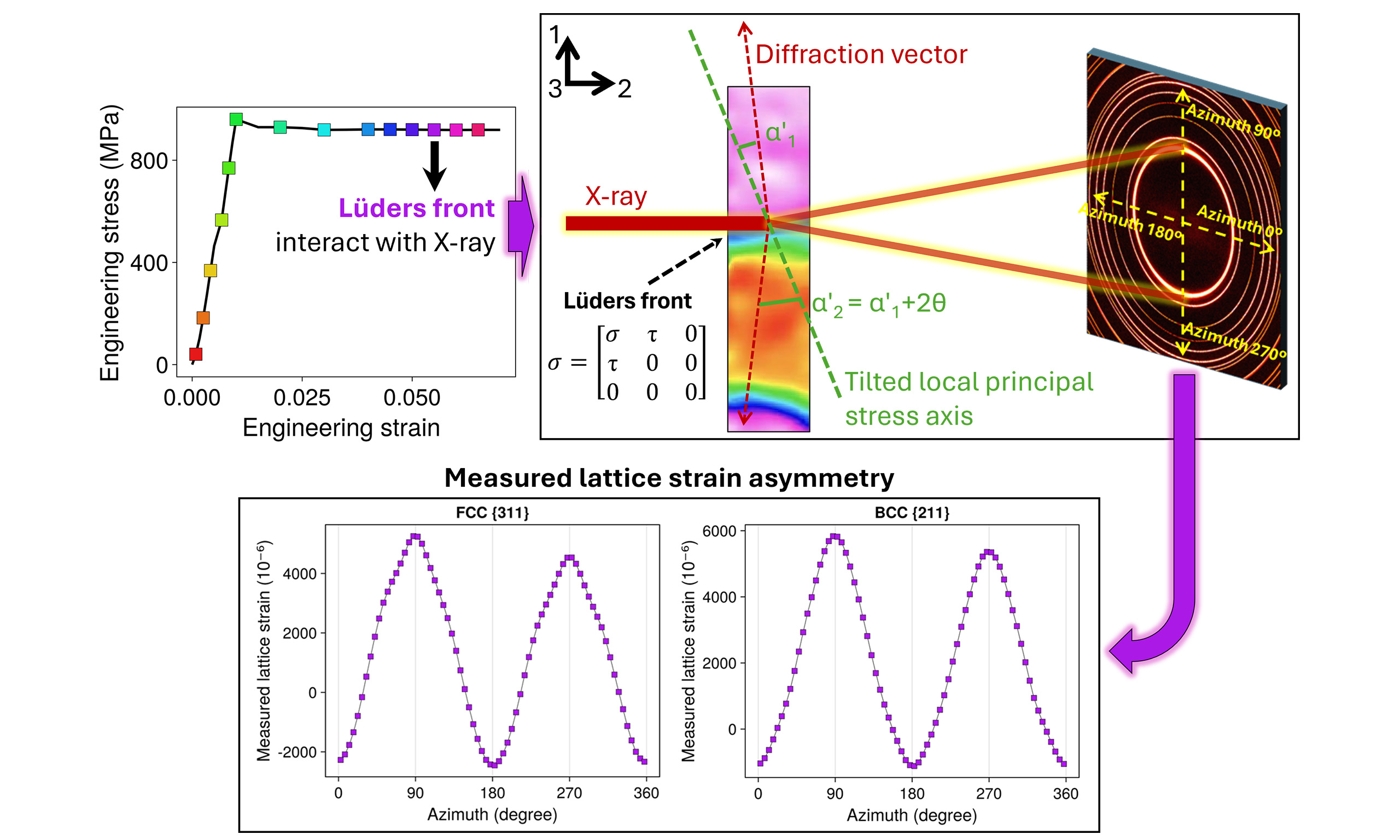
The measured lattice strain distribution curves of the critical strain point of 0.055 for the γ and α/α’ phases are respectively depicted in Figure 7D-F, Figure 8C and D. These curves closely resemble those at elastic strain points in the cosine-function-like shape [Figure 7A-C, Figure 8A and B], suggesting that most of the irradiated volume at this strain point remains in the elastic stage. This observation aligns with the peak intensity and broadening analyses presented in Figures 5 and 6. A notable difference is observed across all analyzed peaks: the measured lattice strain values at azimuth 90° are consistently higher than those of azimuth 270°, as indicated in the figures and parametrically summarized in Table 2. Meanwhile, the minimum measured lattice strain values at azimuths 0° (360°) and 180° remain nearly identical. Such measured lattice strain asymmetry is likely to contain valuable information about the local stress state of the
Measured lattice strain data of the analyzed peaks
| Crystallographic plane | FCC | BCC | |||
| {200} | {220} | {311} | {200} | {211} | |
| Measured lattice strain /10-6 (90°) | 7,896 | 5,333 | 5,255 | 7,901 | 5,833 |
| Measured lattice strain /10-6 (270°) | 6,508 | 3,907 | 4,536 | 7,064 | 5,357 |
| Deviation/10-6 | 1,388 | 1,426 | 719 | 837 | 476 |
The factors contributing to the observed measured lattice strain asymmetry can be examined in terms of microstructure and stress within the irradiated volume. In most reported research employing the same HE-XRD technique, the irradiated volume is generally assumed to be homogeneous in terms of both microstructure and stress. Under stricter assumptions, such as homogeneous deformation upon uniaxial loads, the measured lattice strain would naturally equal the actual lattice strain, i.e., elastic strain. Now consider the present case: a small portion at the upper end of the irradiated volume undergoes severe plastic deformation. As a result, the diffraction peak from this plastically deformed part broadens significantly (may also shift along LD). This broadened and shifted peak, characterized by lower intensity, resembles a background signal when fitting the primary diffraction peak (which remains much more intense and sharper). The primary peak can be chiefly attributed to the elastically deformed portion of the irradiated volume. As schematically shown in Figure 9, where the red lines represent the diffracted beam and Debye ring of the current state, while the dashed black lines indicate the previous state (pure elastic stage), the center of the elastically deformed part shifts downward compared to earlier strain points. Consequently, the recorded Debye ring on the detector moves synchronously toward the 270° azimuth direction, resulting in a lower 2θ angle (and higher measured lattice strain) at 90° azimuth. This condition can lead to the measured lattice strain asymmetry observed in the data.
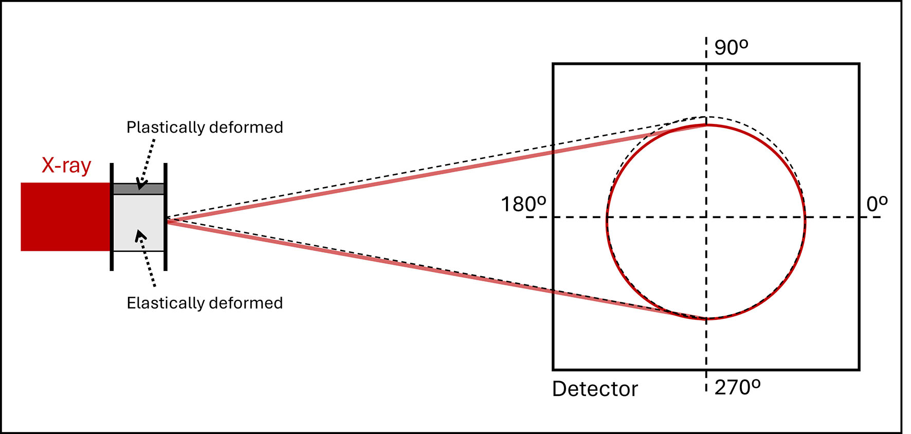
Figure 9. Schematic of the Debye ring shift on the detector due to the
In addition to the microstructural factor discussed above, special stress states can also lead to such measured lattice strain asymmetry. Figure 10A schematically shows the typical diffraction geometry under uniaxial loading, where the local principal stress axis aligns with the applied loading. Under this condition, the deviating angle (α1) between the upper diffraction vector and the principal stress axis at 90° azimuth equals that at 270° azimuth (α2). As a result, the normal stress components along the two diffraction vectors are consistent in magnitude, leading to a symmetric measured lattice strain distribution, as seen in the Debye rings at strain points besides 0.055 [Figure 7A-C, Figure 8A and B]. Previous studies[39,40] have examined the shear deformation characteristics of the
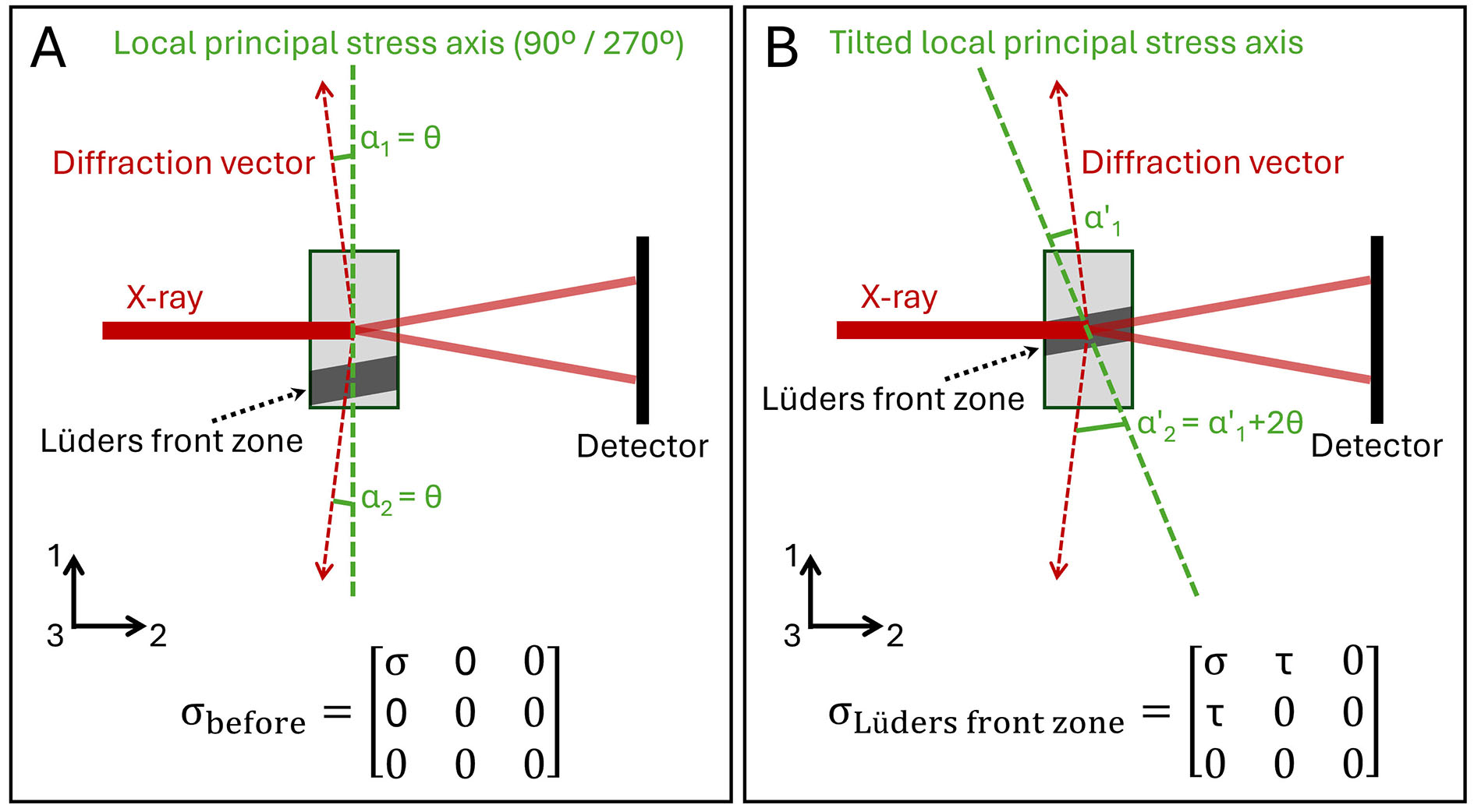
Figure 10. Schematic of the local stress state and the principal stress axis of the irradiated volume before (A) and when (B) overlapping with the
Indeed, both factors discussed above can simultaneously trigger the measured lattice strain asymmetry. As such, it is challenging to isolate and deconvolute their effects based on the data collected in the current experimental setup. Another limitation for the HE-XRD experiment employed in this work is that, strictly speaking, it captures only the local dynamic response, i.e., the detailed evolution of microstructural and stress state at a fixed position of the tensile specimen, which is interacted by the
CONCLUSION
The high-energy X-ray diffraction patterns collected during an in-situ tensile loading test of a medium-Mn TRIP steel specimen were analyzed in terms of the intensity, full width at half maximum (FWHM), and measured lattice strain of diffraction peaks. The features of
DECLARATIONS
Authors’ contributions
Design: Zhang, M.; Li, R.
Experiments: Zhang, M.; Jia, J.; Jia, Z.
Manuscript writing: Zhang, M.; Jia, J.; Li, R.
Manuscript revision and supervision: Feng, Y.; Ma, Z.; Wang, Y. D.; Li, R.
Availability of data and materials
The raw data supporting the conclusions of this article are available from the corresponding author upon reasonable request.
Financial support and sponsorship
This work was financially supported by the National Natural Science Foundation of China (NSFC) (Grant Nos. 51901078), the Natural Science Foundation of Hebei Province (Grant No. E2022209070), Central Government Guided Local Science and Technology Development Funding Project (Grant No. 236Z1003G), and the Tangshan City Science and Technology Plan Project (Grant No. 24130207C). The use of the Advanced Photon Source is supported by the U. S. Department of Energy, Office of Science, Office of Basic Energy Sciences, under Contract No. DE-AC02-06CH11357. Li R and Ma Z are grateful to Prof. Matthew R Barnett for providing research fellow positions financially supported by Laureate Fellowship FL210100147.
Conflicts of interest
Wang, Y. D. is a member of the Senior Editorial Board for the journal Microstructures. Wang, Y. D. was not involved in any steps of editorial processing, notably including reviewer selection, manuscript handling, or decision making, while the other authors have declared that they have no conflicts of interest.
Ethical approval and consent to participate
Not applicable.
Consent for publication
Not applicable.
Copyright
© The Author(s) 2025.
REFERENCES
1. Suh, D. W.; Kim, S. J. Medium Mn transformation-induced plasticity steels: recent progress and challenges. Scr. Mater. 2017, 126, 63-7.
2. Aydin, H.; Essadiqi, E.; Jung, I. H.; Yue, S. Development of 3rd generation AHSS with medium Mn content alloying compositions. Mater. Sci. Eng. A. 2013, 564, 501-8.
3. Guo, Z.; Li, L.; Yang, W.; Sun, Z. Microstructures and Mechanical properties of high-Mn TRIP steel based on warm deformation of martensite. Metall. Mater. Trans. A. 2015, 46, 1704-14.
4. He, B. B.; Huang, M. X. Strong and ductile medium Mn steel without transformation-induced plasticity effect. Mater. Rese. Lett. 2018, 6, 365-71.
5. Han, J.; Lee, S. J.; Jung, J. G.; Lee, Y. K. The effects of the initial martensite microstructure on the microstructure and tensile properties of intercritically annealed Fe-9Mn-0.05C steel. Acta. Mater. 2014, 78, 369-77.
6. Hu, J.; Li, X.; Meng, Q.; Wang, L.; Li, Y.; Xu, W. Tailoring retained austenite and mechanical property improvement in Al-Si-V containing medium Mn steel via direct intercritical rolling. Mater. Sci. Eng. A. 2022, 855, 143904.
7. Tian, G.; Xiao, J.; Bao, Z.; Yao, S.; Yan, L.; Zhao, A. Achieving 1.5 GPa grade medium Mn steel with high ductility via interrupted intercritical annealing process. Mater. Sci. Eng. A. 2024, 905, 145943.
8. Bai, S.; Xiao, W.; Niu, W.; Li, D.; Liang, W. Microstructure and mechanical properties of a medium-Mn steel with 1.3 GPa-strength and 40%-ductility. Materials 2021, 14, 2233.
9. Chen, P.; Wang, J.; Li, X. W. Investigation of the hot-rolled medium-Mn steels with ultra-high strength and considerable ductility. J. Mater. Eng. Perform. 2025, 1-6.
10. Lan, H.; Lin, G.; Ma, Y.; Hu, B.; Du, L. Influence of intercritical annealing on microstructure, ductility, and toughness of medium Mn steels. J. Mater. Eng. Perform. 2025, 34, 14272-84.
11. Steineder, K.; Krizan, D.; Schneider, R.; Béal, C.; Sommitsch, C. On the microstructural characteristics influencing the yielding behavior of ultra-fine grained medium-Mn steels. Acta. Mater. 2017, 139, 39-50.
12. Heo, Y. U.; Suh, D. W.; Lee, H. C. Fabrication of an ultrafine-grained structure by a compositional pinning technique. Acta. Mater. 2014, 77, 236-47.
13. Wang, S.; Chen, W.; Zhao, Z.; Zhao, X.; Luo, X.; Wang, Q. Effect of microstructure evolution on
14. Ma, J.; Lu, Q.; Sun, L.; Shen, Y. Two-step intercritical annealing to eliminate
15. Emadoddin, E.; Akbarzadeh, A.; Daneshi, G. Correlation between Luder strain and retained austenite in TRIP-assisted cold rolled steel sheets. Mater. Sci. Eng. A. 2007, 447, 174-9.
16. Mao, W.; Gao, S.; Gong, W.; Harjo, S.; Kawasaki, T.; Tsuji, N. Quantitatively evaluating the huge
17. Wang, X.; Liu, C.; He, B.; Jiang, C.; Huang, M. Microscopic strain partitioning in
18. Wang, X.; He, B.; Liu, C.; Jiang, C.; Huang, M. Extraordinary
19. Benzing, J. T.; Luecke, W. E.; Mates, S. P.; Ponge, D.; Raabe, D.; Wittig, J. E. Intercritical annealing to achieve a positive strain-rate sensitivity of mechanical properties and suppression of macroscopic plastic instabilities in multi-phase medium-Mn steels. Mater. Sci. Eng. A. Struct. Mater. 2021, 803, 140469.
20. Liu, R.; Hu, Z.; Lin, C.; et al. A novel design to eliminate
21. Qiu, H.; Ueji, R.; Inoue, T. Yield-point phenomenon and plastic bands in ferrite-pearlite steels. Materials 2022, 16, 195.
22. Mao, W.; Gao, S.; Gong, W.; et al. Martensitic transformation-governed
23. Fu, J.; Liu, W.; Sui, H.; Cheng, Y.; Duan, H. Simulations of the localized necking and
24. Sarafanov, G. F.; Shondin, Y. G. Deformation instability in crystalline alloys:
25. Sun, B.; Ma, Y.; Vanderesse, N.; et al. Macroscopic to nanoscopic in situ investigation on yielding mechanisms in ultrafine grained medium Mn steels: Role of the austenite-ferrite interface. Acta. Mater. 2019, 178, 10-25.
26. Ma, Y.; Sun, B.; Schökel, A.; et al. Phase boundary segregation-induced strengthening and discontinuous yielding in ultrafine-grained duplex medium-Mn steels. Acta. Mater. 2020, 200, 389-403.
27. Liang, Z.; Cao, Z.; Lu, J.; Huang, M.; Tasan, C. Influence of co-existing medium Mn and dual phase steel microstructures on ductility and
28. Luo, H.; Dong, H.; Huang, M. Effect of intercritical annealing on the
29. Zhang, M.; Li, R.; Ding, J.; et al. In situ high-energy X-ray diffraction mapping of
30. Yan, S.; Yu, Z.; Liang, T.; et al. Unusual step-like stress flow behavior and mechanisms of a 1.3 GPa grade medium-Mn steel with
31. Han, J.; Wang, J.; Manladan, S. M.; et al. Effect of
32. Ma, J.; Liu, H.; Lu, Q.; Zhong, Y.; Wang, L.; Shen, Y. Temperature-dependent macroscopic mechanical behaviors and their microscopic explanations in a medium Mn steel. Metall. Mater. Trans. A. 2020, 51, 5180-6.
33. Liu, Y.; Jiang, J.; Li, Y.; et al. Correlation of TRIP effect and
34. Wang, X.; Wang, L.; Huang, M. Kinematic and thermal characteristics of
35. Liu, C.; Hu, C.; Wang, X.; Huang, M.; Jiang, C. A new perspective on
36. Varanasi, R. S.; Zaefferer, S.; Sun, B.; Ponge, D. Localized deformation inside the
37. Zhang, M.; Tan, Q.; Ding, J.; et al. In situ high-energy X-ray diffraction investigation of the micromechanical behavior of Fe-0.1C-10Mn-0/2Al steel at room and elevated temperatures. Mater. Sci. Eng. A. 2018, 729, 444-51.
38. Lobodyuk, V. A.; Meshkov, Y. Y.; Pereloma, E. V. On tetragonality of the martensite crystal lattice in steels. Metall. Mater. Trans. A. 2019, 50, 97-103.
39. Maruyama, N.; Yamamoto, M.; Tabata, S. Microscopic shear deformation characteristics of the
Cite This Article
How to Cite
Download Citation
Export Citation File:
Type of Import
Tips on Downloading Citation
Citation Manager File Format
Type of Import
Direct Import: When the Direct Import option is selected (the default state), a dialogue box will give you the option to Save or Open the downloaded citation data. Choosing Open will either launch your citation manager or give you a choice of applications with which to use the metadata. The Save option saves the file locally for later use.
Indirect Import: When the Indirect Import option is selected, the metadata is displayed and may be copied and pasted as needed.
About This Article
Special Topic
Copyright

Data & Comments
Data
0


Comments
Comments must be written in English. Spam, offensive content, impersonation, and private information will not be permitted. If any comment is reported and identified as inappropriate content by OAE staff, the comment will be removed without notice. If you have any queries or need any help, please contact us at [email protected].