


Atomistic underpinnings for dislocation emission behaviors at the crack tips in FCC metals in light of thermo-kinetic synergy
 0
0 
Abstract
Dislocation emission at the crack tips in faced-centered cubic (FCC) metals generally involves multiple mechanisms of dislocation nucleation dominated by the motion behaviors of atoms near the crack tips. Taking FCC aluminum as a representative, in this work, the emission behaviors and nucleation mechanism of dislocations at the crack tips in FCC metals are investigated in light of the continuum mechanics models within the framework of the anisotropic linear elastic fracture mechanics. The system energy evolution and motion behaviors of atoms near the crack tips under Mode I loading conditions are obtained first by performing molecular dynamics simulations. The underlying thermo-kinetic origins of dislocation emission are clarified based on driving force U and energy barrier
Keywords
INTRODUCTION
Compared with the body-centered cubic (BCC) and hexagonal-close packed (HCP) metals with fewer slip systems, their faced-centered cubic (FCC) counterparts (such as Al, Cu, Ni and their alloys) exhibit higher fracture toughness due to the excellent deformation capability and abundant dislocation slip mechanisms[1-4], and thus have been widely used in aerospace, nuclear energy, and automotive manufacturing industries. However, the fracture toughness can be deteriorated in extreme service environments (such as low temperatures, high strain rates or irradiation), and even cause brittle fracture[5]. At the atomistic scale, the fracture toughness is determined by the motion behaviors of atoms and/or atom groups at the crack tips[6]. Specifically, the crack propagation usually originates from stress concentration, and the elastic strain energy accumulated at the crack tips is released by generating new crack surfaces. The crack tips in FCC metals can emit dislocations, which can blunt themselves to reduce the curvature radius of crack tips, thus releasing the local stress concentration and decreasing the driving force for crack propagation, which is beneficial for the fracture toughness. Furthermore, the overlap between the external loads and the stress field generated by crack-tip dislocations can partially compensate for the applied stress intensity factor. Such a shielding effect equivalently decreases the driving force for crack propagation, which can delay crack propagation and benefit the fracture toughness. The magnitude of applied load required for dislocation nucleation, as a key point for entire dislocation emission behaviors, determines the competition between dislocation emission and crack propagation. In contrast, the location of dislocation nucleation influences subsequent motion behaviors of atoms and/or atom groups near the crack tips. Therefore, it becomes of considerable significance to investigate the critical conditions for dislocation nucleation and the evolution rules of dislocation at the crack tips for enhancing the fracture toughness of FCC metallic alloys.
The existing literature has made much progress on dislocation emission behaviors at the crack tips based on the continuum mechanics models within the framework of anisotropic linear elastic fracture mechanics (ALEFM)[7-10]. By extending the traditional Peierls concept[11], Rice investigated the dislocation emission behaviors at the crack tips[12], under the assumption that the shear stress τ on slip plane is periodically related to the atomic displacement δ. Based on the Peierls-Nabarro model[11,13] and the J integral involved in elastic-plastic fracture mechanics[14], quantitative correlations between the indices of fracture toughness (including the stress intensity factor K and energy release rate G) and stacking fault (SF) energy were established. This avoids the drawbacks in traditional dislocation theory proposed by Rice and Thomson[10], which involves an empirical parameter of dislocation core radius for describing energy of dislocation core region.
The critical stress intensity factor of dislocation emission under the Mode I (tensile opening) loading conditions was expressed as:
Subsequently, a new theory for dislocation emission at the crack tips, which broke through the limitations of Rice’s theory[12], was proposed by Andric and Curtin[15]. It was regarded that dislocation emission is a process of mechanical instability at the crack tips, rather than a process of thermal activation in Rice’s theory[12], where the energy with magnitude of unstable SF energy γusf is required to overcome for dislocation nucleation. Based on the competitive correlation between applied shear stress τapp and restoring shear stress τres, a criterion for evaluating crack stability with differential form was expressed as: dτapp/dΔ ≥ dτres/dΔ[15], which can be used to capture the chain instability phenomenon caused by slight perturbations and to describe the non-equilibrium transient state such as dislocation emission, with Δ being the displacement of structural unit at the crack tips. As such, a predictive model for critical energy release rate GIe was developed by Andric and Curtin[12] based on the unstable SF energy γusf and surface energy γs, which considerably reduced the predictive derivation of Rice model[12] from 20%-50% to < 10%. Accordingly, a more general framework for dislocation emission theory has been established[16,20,22], which provides a theoretical foundation for understanding the correlations between intrinsic ductility and different deformation mechanisms such as blunting and propagation at the crack tips.
The accuracy of the aforementioned theoretical models for predicting the critical conditions of dislocation emission at the crack tips has been validated by relevant atomistic simulations[23-25]. However, a lot of these simulation works focus on the initial emission of dislocations at the crack tips. For most FCC metals, the nucleation mechanism of subsequently emitted dislocations at the crack tips changes[26], and thus relevant nucleation mechanism of the initial dislocation emission is no longer suitable. The nucleation mechanism of the trailing dislocations at the crack tips was considered in Rice’s theory[12], where the leading partial dislocations and trailing partial dislocations move on the same slip plane. A series of atomistic simulations[25] found that the trailing dislocations are rarely emitted in FCC metals; instead, the second partial dislocation is emitted on adjacent slip plane of the first dislocation emission, thus forming a two-layer twinning zone. Following Rice’s theory[12], the unstable twinning fault energy γutf was defined by Tadmor and Hai[22] analogous to the unstable SF energy γusf, the magnitude of which represents the maximum potential barrier to be overcome by the crystal when it transforms from a stable SF to an unstable twinning configuration during shear deformation. This energy serves as a key parameter in the nucleation energy expression for the twinning partial dislocation in FCC metals[22]. Consequently, a nucleation criterion[22,27] for twinning partial dislocation was proposed in analogy with that for trailing partial dislocation at the crack tips. However, the critical stress intensity factor predicted from the Tadmor-Hai theory[22] is 20%-35%, lower than that from the molecular statics simulations[15]. Such deviation originates from the two fundamental limitations of the Tadmor-Hai model[22]: (i) the nucleation of twinning dislocation at the second structural unit rather than at the crack tips, resulting in the resolved shear stress on the position for dislocation nucleation lower than that at the crack tips; (ii) the simplification involved in Mode I loading conditions used in Rice’s theory[12]. To address these shortcomings, a correction factor f(Cijkl) was introduced by Andric and Curtin[27], which accounts for the displacement effect of the local stress field caused by variations in the position of dislocation nucleation at the crack tips. Accordingly, an accurate mapping from far-field loads to local shear stress was achieved[27], enhancing the accuracy of Curtin’s model[27] for predicting the critical stress intensity factor KIe and the derivation from molecular statics simulation decreases within 5%.
The critical conditions for dislocation emission at the crack tips can be quantitatively assessed by the above models based on the continuum mechanics theory. However, these models primarily focus on specific mechanisms of dislocation emission at the crack tips[12,15,22,27]. In fact, the stress field at the crack tips undergoes continuous variations from the initial loading moment to the crack propagation process, signifying connections among different behaviors of dislocation emission at the crack tips. For example, the correction factor f(Cijkl) in Curtin’s model[27] for twinning partial dislocation emission, changes with the number of dislocation emissions due to the continuous movement of dislocation nucleation position, but the variation trend remains elusive. Therefore, it is crucial to investigate the transition among different mechanisms of dislocation nucleation at the crack tips and the variations in characteristics of dislocation emission behaviors at the crack tips.
Intrinsically, the dislocation emission at the crack tips is dominated by both thermodynamic and kinetic factors. Specifically, the thermodynamics corresponds to the storing elastic strain energy released by the crack tips, prior to which the formation energy of different defects such as dislocation and twinning at the crack tips must be included, and this energy is provided by the external loads generally[28]. The kinetics reflects the different mechanisms of dislocation nucleation at the crack tips, which is dominated by the magnitude of dislocation nucleation energy[29]. The combinations of driving force and energy barrier for dislocation emission determine the characteristics of dislocation behaviors at the crack tips. In this regard, the existing works primarily focused on the critical conditions for dislocation nucleation at the crack tips in FCC metals, which belongs to the thermodynamic scope and ignores the kinetic process of dislocation emission. In principle, both the frequency of dislocation emission at the crack tips and the velocity of dislocation motion belong to the kinetic scope[30], which exerts direct influence on deformation mechanism and fracture toughness of FCC metals in terms of variations in atomic configuration near the crack tips. Therefore, the entire dislocation emission behaviors at the crack tips are dominated by the thermo-kinetic synergy.
In this work, the emission behaviors and nucleation mechanisms of dislocations at the crack tips in FCC aluminum (Al) under the Mode I loading conditions are investigated from the perspective of thermo-kinetic synergy. The motion behaviors of atoms and/or atom groups near the crack tips, along with system energy evolution curves, are obtained by performing molecular dynamics (MD) simulations. The critical values for atomic displacement during dislocation emission are acquired through identifying the sudden changes in instantaneous displacement of structural units at the crack tips. In combination with the continuum mechanics model of ALEFM[7], the critical conditions for dislocation emission at the crack tips in FCC metals were derived. It turns out that under different mechanisms of dislocation nucleation, the variations in the potential barrier of dislocation nucleation derive from the distinctions in atomic configurations at the crack tips. The driving force and energy barrier for dislocation emission at the crack tips were determined from the system energy variations, based on which the system energy evolution rule of dislocation emission under the same mechanism of dislocation nucleation is clarified, along with the variations in potential barrier to be overcome for dislocation nucleation under different mechanisms. Accordingly, a thermo-kinetic criterion for the mechanism transition of dislocation nucleation at the crack tips in FCC metals is proposed in light of the system energy change.
MATERIALS AND METHODS
Theoretical models
Herein, the continuum mechanics models within the ALEFM framework[31] are used to obtain the stress distribution near the crack tips in FCC Al. When dislocations are emitted at the crack tips, various defects such as SFs, twinning, and free surfaces form near the crack tips[22,32], triggering rearrangement of atoms near the crack tips to release the elastic strain energy, and thus enhancing the stability of crack tips. By analyzing the formation energy of these defects, the critical conditions for dislocation emission at the crack tips in FCC metals can be obtained from the thermo-kinetic variations.
Continuum mechanics models for initial dislocation nucleation at the crack tips
The dislocation emission is triggered by the local mechanical instability of structural unit at the crack tips[29]. When the applied load cannot balance the restoring stress caused by the formation of step surface, the stress equilibrium at the crack tips will be broken, reducing the stability of crack tips and promoting dislocation nucleation at the crack tips[29]. The restoring stress τres at the crack tips can be obtained in light of the Peierls model[12] via:
where g represents the ratio of restoring stress at the crack tips with and without a “surface step”. Equation (1) restores to the expression for restoring stress in Rice model (τgsf)[12] when g = 1. The energy criterion for dislocation emission at the crack tips can be obtained by integrating the restoring stress over the displacement under the critical condition for dislocation emission[15], i.e., J = GIe. This signifies that the total energy released during dislocation nucleation at the crack tips is equal to the critical energy release rate, as given by:
where Ψnuc represents the energy required for dislocation nucleation containing step energy, Ψgsf indicates that for dislocation nucleation considering only SF formation. Δic signifies the critical displacement of the
Apparently, GIe is contributed from the unstable SF energy γusf and the surface energy γs (associated with the surface step energy). As such, the critical energy release rate GIe for the initial dislocation emission at the crack tips in FCC Al can be obtained.
Continuum mechanics models for twinning dislocation nucleation at the crack tips
Once the first partial dislocation is emitted at the crack tips, the local stress concentration spreads out[6], which makes the atomic structure near the crack tips satisfy the critical condition for dislocation emission. In principle, there are three scenarios[22] for subsequent dislocation emissions at the crack tips in FCC metals: (i) Trailing partial dislocation emission, where the second partial dislocation nucleates on the same slip plane as the first partial dislocation. The two partial dislocations react to form a full dislocation, moving away from the crack tips; (ii) Twinning partial dislocation emission, where the second partial dislocation nucleates on the adjacent slip plane of the first partial dislocation at the crack tips. This generates a twinning zone with a thickness of two atomic layers, which promotes the blunting phenomenon of the crack tips; (iii) Partial dislocation emission at non-adjacent slip planes, where the second partial dislocation nucleates on a non-adjacent slip plane of the first partial dislocation at the crack tips. This forms two separated SF regions, which can transform into a twinning zone with a thickness of three atomic layers during subsequent dislocation emission. In fact, the twinning partial dislocation emission is the most common in FCC Al[28]. Following the Peierls concept[12], a predictive model of the critical stress intensity factor
where F12(θ) denotes the stress decomposition factor, which is a function of the angle θ between the slip plane and the crack plane, while the geometric factor p(θ,φ) is a function of θ and the angle φ between the Burgers vector of emitted dislocation and the crack propagation direction [Figure 1A]. In general, the critical stress intensity factor of twinning dislocation emission in FCC metals is smaller than that of trailing dislocation emission[22], i.e.,
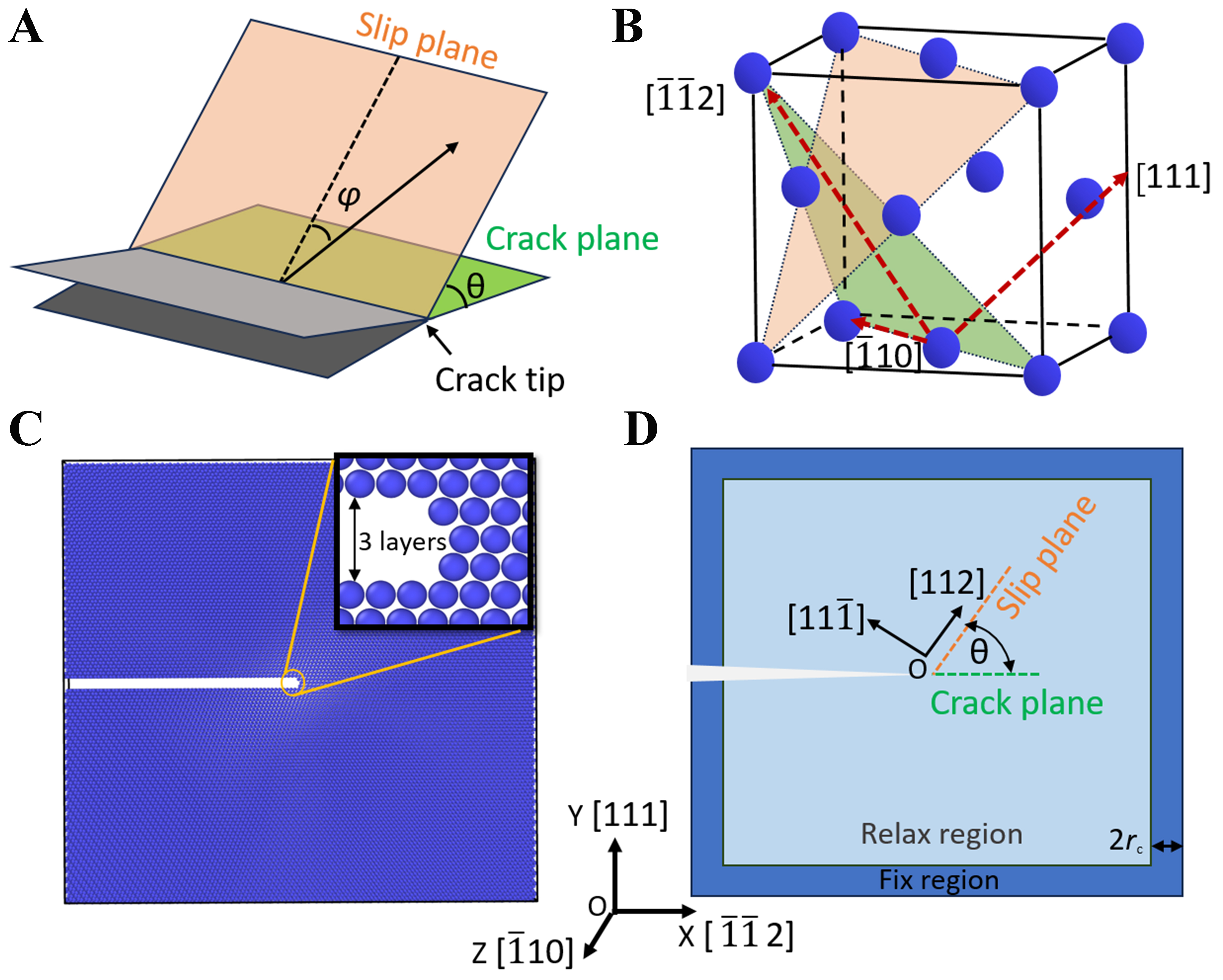
Figure 1. Schematic diagram for the structural model of FCC Al under the K-field loading conditions for atomistic simulations. (A) The direction of dislocation emission at the crack tips, where θ is the angle between the crack plane and slip plane, and φ is the angle between the dislocation emission direction and crack propagation direction; (B) The slip systems involved in dislocation emission at the crack tips, where the triangular region represents the {111} slip plane, and the direction of dislocation emission from the crack tips is along the <112> direction; (C) Atomic configuration of FCC Al with a marginal crack, where the X, Y, and Z axes of the simulation box are along the [
where f(Cijkl) is the elastic correction factor obtained via elastic analysis on the stress field at the crack tips, and Cijkl is the elastic constant.
Equation (5) resolves the discrepancy of critical stress intensity factor at the crack tips between predictions and atomistic simulations, providing a robust foundation for understanding dislocation emission behaviors at the crack tips in FCC metals. Following thermodynamic extremal principle[27], the dislocation emission at the crack tips always tends to the energy minimization while the defect formation is with the smallest energy barrier, regardless of the varied dislocation nucleation mechanism. Therefore, it is in urgent demand to identify the universal laws governing subsequent dislocation emission behaviors at the crack tips in FCC metals based on the thermo-kinetic synergy.
Computational procedures
Considering the slight deformations and plane strains of the ALEFM theory[7], herein the applied load in the “K-field” loading model, i.e., the ALEFM-MD coupled model, is imposed via displacements near the crack tips generated by the “K-field” in the anisotropic continuum[29]. For MD simulations, the magnitude of applied load is regulated by the stress intensity factor K, which enables an accurate description of atomic-scale behaviors of the crack tips and quantifies the critical stress intensity factor of cleavage/dislocation emission at the crack tips[7]. The reasonability for such settings in MD simulations of the Mode I and Mode II loading conditions has been verified in previous work[15,22,23].
As such, the atomistic configuration with a preset crack in FCC Al was constructed [Figure 1B], where the <112> direction on the (
For MD simulations, the free boundary condition was used for the X and Y axes, while the periodic boundary condition was used for the Z axis of the simulation box. The Mode I loading conditions for cracks in FCC Al were achieved by applying a displacement field, where all atoms move Δux and Δuy along the X and Y axes at each loading time, respectively. The displacement increment Δux and Δuy[33] is given as:
where the initial value and the increment of the stress intensity factor are set as KI = 0.1 MPa·m1/2 and ΔK = 0.001 MPa·m1/2, respectively. Figure 1D shows that after applying each displacement, those atoms within 2rc (with rc being cutoff radius of the interatomic potential) region from the simulation box boundary were fixed, while the remaining atoms were minimized to reach equilibrium. The simulations were carried out at 0 K to eliminate the influence of thermal vibrations on the dislocation emission behaviors at the crack tips. The embedded atom method (EAM) potential developed by Mishin et al.[34], which has been used extensively to investigate dislocation nucleation behaviors[25], was employed to describe the atomic interactions in FCC Al. The energy minimization includes three steps: (i) using the conjugate gradient method (CG)[35] for coarse optimization (with energy tolerance of 1 × 10-20 eV) to relax the long-range elastic strains rapidly; (ii) using the fast inertial relaxation engine (FIRE)[36] algorithm (with energy tolerance of 1 × 10-12 eV) for local atomic rearrangements at the crack tips to overcome the drastic oscillations of the potential energy surface; and (iii) using the high-precision CG optimization[35] (with energy tolerance of 1 × 10-25 eV) for eliminating the residual stress waves to ensure system at sub-angstrom scale displacement accuracy. Subsequently, the atoms were re-displaced and the cycle repeats 500 times with increasing the stress intensity factor from KI = 0.1 to 0.6 MPa·m1/2. The maximum atomic displacement was set as dmax = 0.05 Å to prevent system’s excessive relaxation. Such a three-step method can avoid the metastable states induced by traditional single minimization, and can precisely capture the critical state of dislocation emission at the crack tips by progressively tightening the convergence criteria[37].
RESULTS
Characteristics of structural evolution during dislocation emission at the crack tips in FCC Al
Figure 2 shows the evolution of atomic structures perpendicular to [
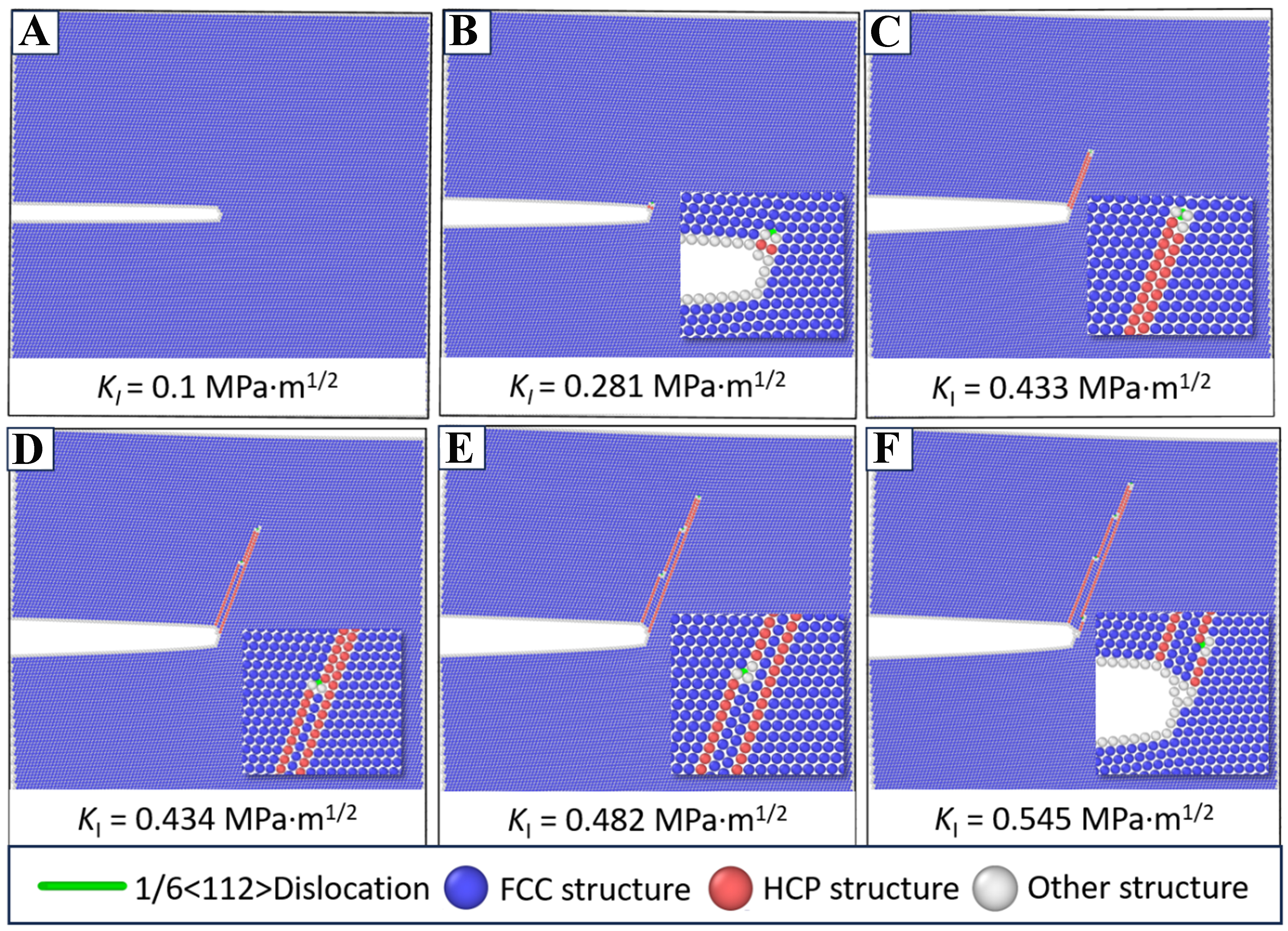
Figure 2. Snapshots for evolution of atomic configurations along the direction perpendicular to [
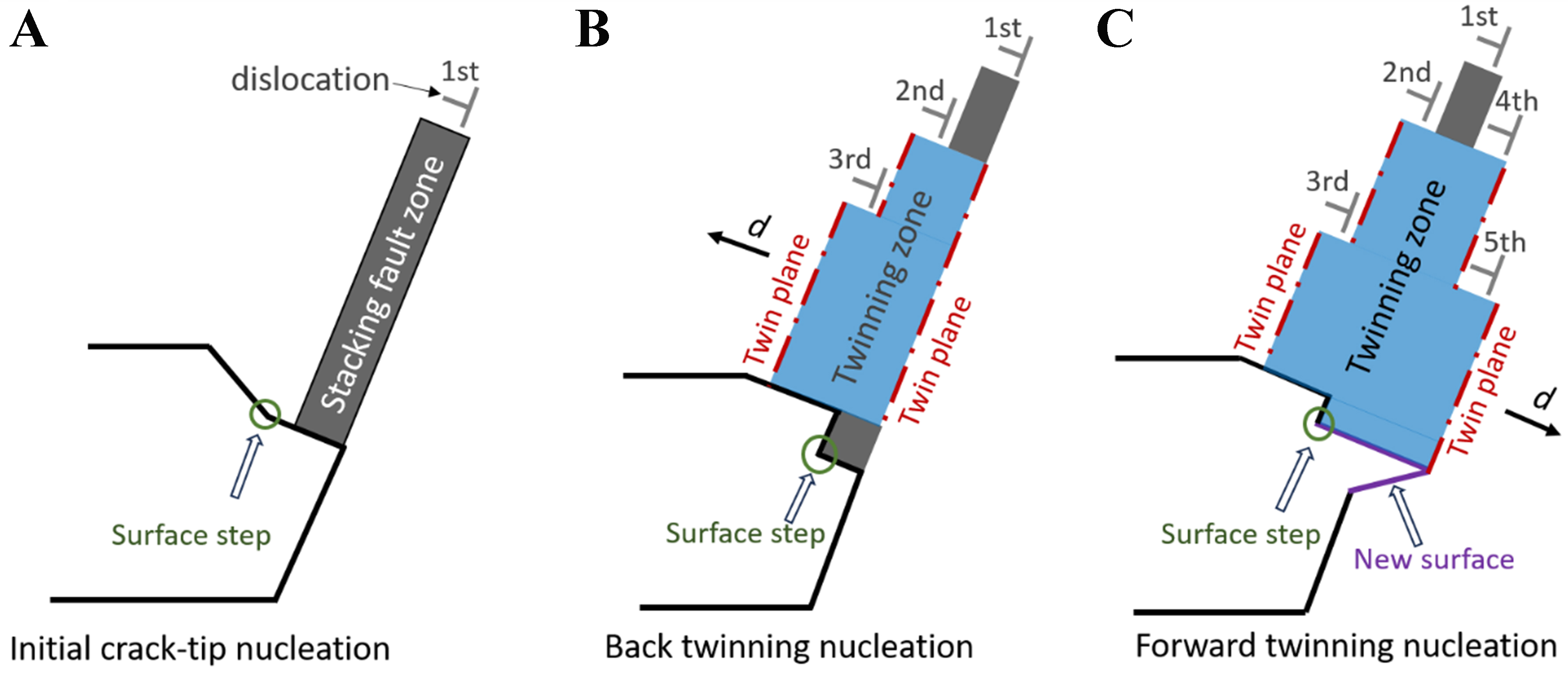
Figure 3. Schematic illustration for the formation and evolution of defects near the crack tips under different mechanisms of dislocation nucleation at the crack tips in FCC Al. (A) The initial dislocation nucleation at the crack tips accompanied by the formation of SF zone and a surface step on the dislocation propagation plane; (B) The back twinning dislocation nucleation at the crack tips, with the dislocation nucleation occurring on the slip plane adjacent to previous dislocation and the corresponding SF zone transforms into the twinning zone with stepwise shape due to the position distinctions in dislocation nucleation at the crack tips; (C) The forward twinning dislocation nucleation at the crack tips, with the dislocation nucleation occurring on the slip plane at the right of the first partial dislocation accompanied by instability of the crack tips and the corresponding twinning zone extended toward the crack tips. FCC: Faced-centered cubic; SF: stacking fault.
With the stress intensity factor increasing to KI = 0.434 MPa·m1/2, the second partial dislocation at the crack tips nucleates on the (
With the stress intensity factor increasing to KI = 0.482 MPa·m1/2, the third partial dislocation appears at the crack tips [Figure 2E], where nucleation of this dislocation occurs on the adjacent slip plane of the second partial dislocation. The nucleation mechanism of this dislocation remains the same as the second partial dislocation, while the distinction lies in the nucleation position. Meanwhile, the SF zone related to the third partial dislocation forms an atomic step on the previous SF zone generated by the second partial dislocation. Besides, the twinning zone is extended via emerging the SF zones with the same width of the third partial dislocation and that of the first and second partial dislocations at the crack tips [Figure 3B]. Consequently, the twinning zone thickness along the crack ending direction increases to 7.014 Å, i.e., three times the interplanar spacing of the (
The nucleation of the fourth partial dislocation occurs on the right slip plane of the first partial dislocation, rather than on the left boundary of the twinning zone, while the newly formed SF zone merges with the SF zone related to the previous three partial dislocations to form a twinning zone with larger thickness. However, the twinning expansion direction is no longer toward the crack end, but along the crack expansion direction. This signifies that the mechanism transforms from the back twinning dislocation nucleation of the second and third partial dislocations to the forward twinning dislocation nucleation of the fourth partial dislocation [Figure 3C]. The predicted results have been confirmed by experimental characterization[38] where certain crack propagation occurs through twinning nucleation ahead of the crack tips and the twinning serves as the nucleation sites for further cleavage.
As shown in Figure 4, the predictions for emission behaviors and nucleation mechanisms of dislocations at the crack tips in FCC Al are in accordance with the experimental observations reported previously[38]. For instance, the present MD simulations on the atomic behaviors of stress intensity factor of KI = 0.281 MPa·m1/2 [Figure 4A], agree well with the in-situ transmission electron microscopy (TEM) observations reported by Kou et al. that the first dislocation emission from the crack tips in FCC Al generates an atomic-scale surface step with a height equivalent to one {111} interplanar spacing [Figure 4B][38]. The twinning mechanism [Figure 4C] coincides with the TEM observations[38] as well [Figure 4D]. Besides, these available experimental findings confirm the retraction behaviors along the crack edge during crack propagation in FCC Al, which agrees with the atomic-scale step formation during the initial dislocation emission at the crack tips captured in the present work. Meanwhile, subsequent dislocation emissions mainly initiated from the intersection of the crack tips and coherent twinning boundaries, which serve as favorable sites for dislocation nucleation due to the geometric constraints and stress concentration. Moreover, the in-situ TEM experiments[38] confirmed that the twinning boundary migration is mediated by the glide of parallel Shockley partial dislocations on the {111} slip plane, which expands the twinning region progressively. This is consistent with the presently predicted back twinning mechanism of dislocation nucleation at the crack tips. As such, the present work demonstrates that the twinning formation and crack propagation are mediated by alternating slip of Shockley partial dislocations in FCC Al.
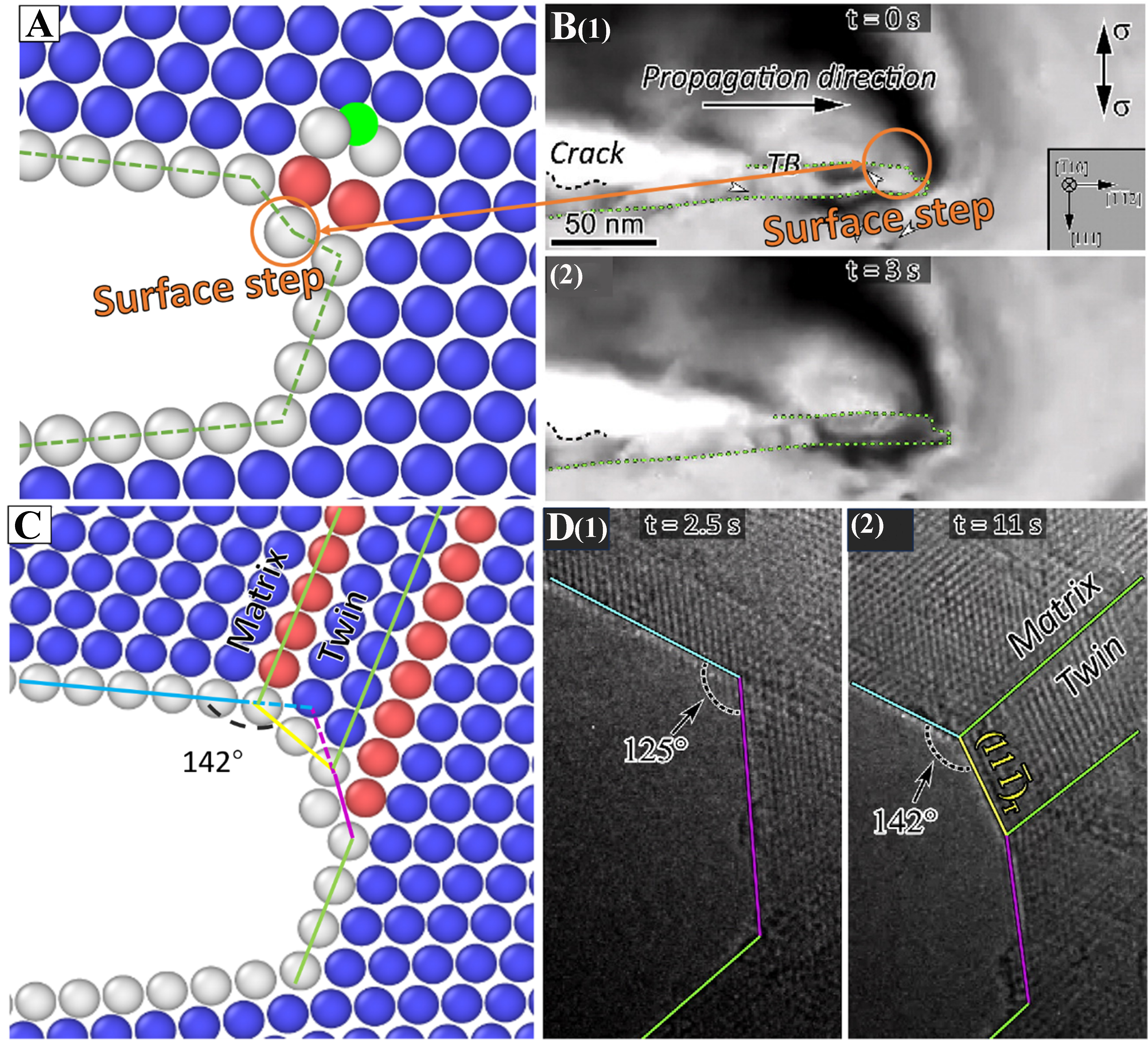
Figure 4. Comparisons between the present work and the TEM observations[38] on the initial dislocation emission and back twinning dislocation emission at the crack tips in FCC Al. (A) MD simulation and (B) TEM characterization[38] for surface step formation; (C) MD simulation and (D) TEM characterization[38] for twinning dislocation formation. TEM: Transmission electron microscopy; FCC: faced-centered cubic; MD: molecular dynamics.
Thus, different combinations of various defects generated during dislocation emission reflect the different mechanisms of multiple dislocation nucleation at the crack tips in FCC Al. Specifically, the emission of the first partial dislocation is dominated by the crack-tip nucleation accompanied by the formation of surface steps. The emission of the second and third partial dislocations is dominated by the back twinning dislocation nucleation accompanied by the formation of twinning zones with stepwise shape. The emission of the fourth partial dislocation is dominated by the forward twinning nucleation and manifests as the crack propagation and thickening of the twinning zone along crack tip direction. The abovementioned defects originate from variations in displacement of atoms near the crack tips in FCC Al, because the atomic displacement exerts direct influences on the magnitude of local strain. Once the atomic displacement reaches the critical condition, various defects will form to maintain the system stability. Therefore, it is necessary to understand the structural characteristics of the crack tips and their evolution rule based on the atomic displacement.
Atomic displacement criteria for dislocation emission at the crack tips in FCC Al
The critical conditions for dislocation emission can be determined from the displacement variations of atoms near the crack tips in FCC Al. In general, dislocation emission originates from the relative displacement of atomic pairs in the structural units at the crack tips. Specifically, the structural unit for dislocation emission at the crack tips in FCC Al under the Mode I loading conditions is defined as follows: (i) The two atoms overlapped between the SF zone formed by the first partial dislocation emission at the crack tips and the dislocation emission plane are denoted as the atomic pair 1 and 1’, and the corresponding displacement difference between these two atoms is denoted as Δ1; (ii) The two atoms adjacent to the atomic pair 1 and 1’ along the [112] direction are denoted as the atomic pair 2 and 2’, with the corresponding displacement difference as Δ2. When the first partial dislocation is emitted at the crack tips, the critical value of Δ1 (Δ1c = 0.35 bp) is smaller than that of Δ2 (Δ2c = 0.36 bp) [Figure 5A], which disagrees with Curtin’s theory[15]. To this end, the displacement difference Δ3 between the atomic pair 3 and 3’ is obtained. The ratio of the critical displacement differences is Δ1c/Δ3c= 0.64, which is close to that from the statistical result[15]. Figure 5B shows that when the second partial dislocation is emitted from the crack tips in FCC Al, the critical value for the displacement difference of the second structural unit, i.e., ΔIc = 0.21 bp, is smaller than that of the first structural unit, i.e., Δ1c = 0.35 bp. This indicates that the nucleation rate of the second partial dislocation is faster than that of the first partial dislocation. When the third partial dislocation is emitted at the crack tips in FCC Al [Figure 5C], the increment of displacement difference in the third structural unit approaches 0.68 bp, which is smaller than that in the second structural unit (i.e., 0.83 bp). This indicates that the energy required to dissipate for emission of the third partial dislocation is lower than that of the second partial dislocation.
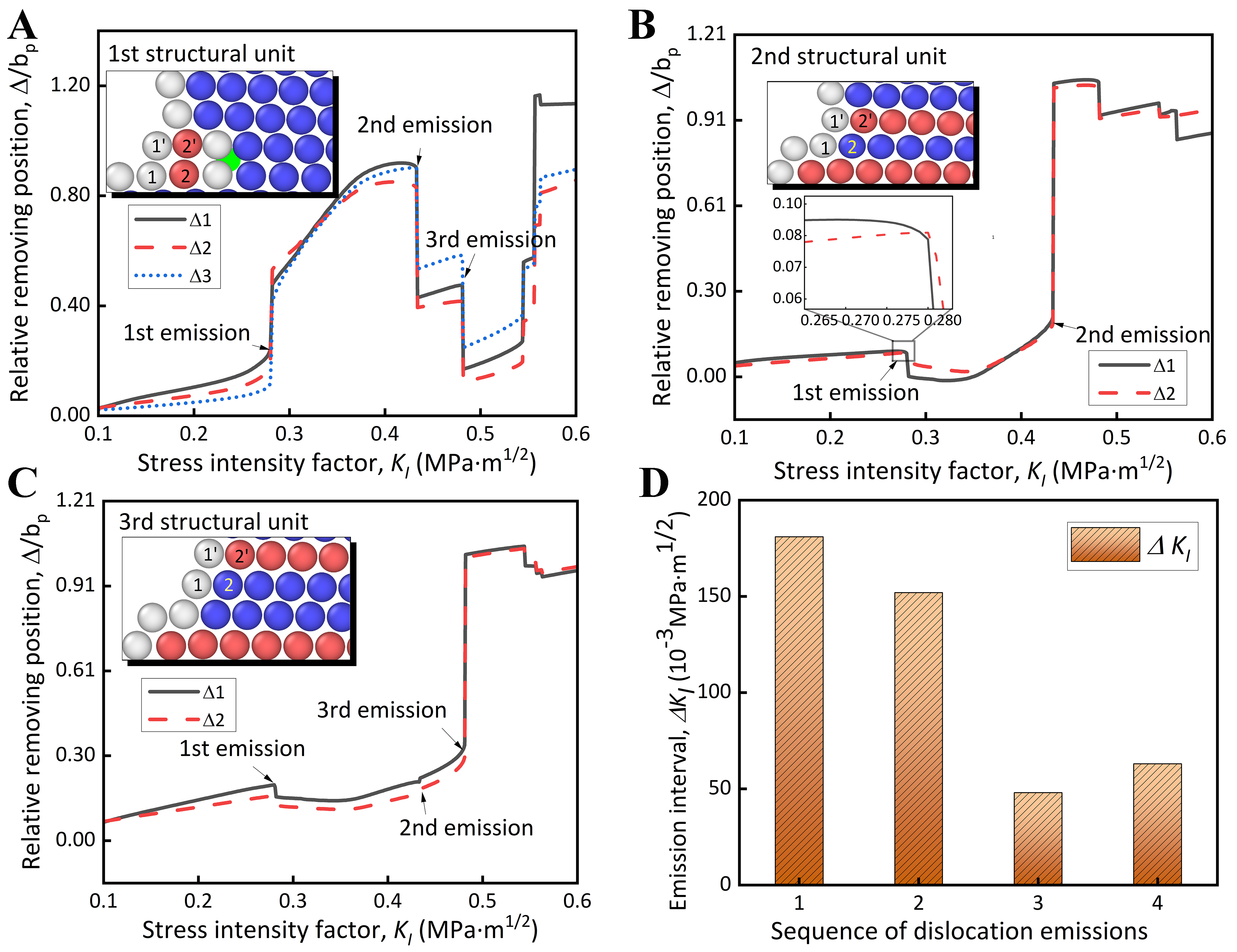
Figure 5. The displacement curves of atomic pairs in different structural units near the crack tips in FCC Al with respect to the stress intensity factor, along with the interval variations in stress intensity factor for each dislocation emission at the crack tips. The differences in displacement of atomic pairs 1 and 1’, 2 and 2’, and 3 and 3’ as a function of stress intensity factor during dislocation emission of (A) the first structural unit, (B) the second structural unit, and (C) the third structural unit; (D) Incremental changes in stress intensity factor among emission of four partial dislocations at the crack tips. FCC: Faced-centered cubic.
The atomic displacement at the crack tips reflects the distribution and dissipation of energy within the crack tip stress field. Analysis of the first three dislocation emission events reveals that with rising distance between the structural units emitting dislocations and the crack tips, the critical displacement for dislocation emission increases progressively. This confirms that the crack tips have the highest energy, and the dislocation emission occurring far from the crack tips has to overcome a larger energy barrier. The atomic displacement associated with the three dislocation emissions reaches the maximum during the second dislocation emission, indicating that the SF zone formed by the second dislocation emission has the largest width and consumes the most energy. This suggests a potential transformation for the type of defects formed during dislocation emission at the crack tips compared to previous emissions. The emission of arbitrary partial dislocations at the crack tips in FCC Al can delay the emission of subsequent partial dislocations [Figure 5A-C]. Detailed analysis is provided in the Supplementary Materials.
The increment of stress intensity factor for each dislocation emission can be used to estimate the ease or difficulty of dislocation nucleation at the crack tips. Figure 5D shows that when the stress intensity factor increases to KI = 0.282 MPa·m1/2, the first partial dislocation emits at the crack tips in FCC Al. The interval of dislocation emission at the crack tips expands gradually as the applied load increases. The interval between the stress intensity factor for emission of the first and second partial dislocations is ΔKI = 0.152 MPa·m1/2, while that for emission of the second and third partial dislocations is only ΔKI = 0.048 MPa·m1/2. However, the interval between the stress intensity factor for emission of the third partial dislocation and the fourth partial dislocation increases to 0.064 MPa·m1/2, which is attributed to the mechanism transition for dislocation nucleation at the crack tips. Thus, the ease or difficulty for dislocation emission at the crack tips in FCC Al is dominated by the synergistic effects of the applied stress intensity factor and the dislocation nucleation mechanism. Based on Equation (2), the system energy is a function of atomic displacement at the crack tips, and the critical conditions for dislocation emission can be captured from the abrupt changing points on the system energy evolution curve. Thus, the system energy dissipation can also serve as an indicator of dislocation emission at the crack tips. Moreover, the magnitude of energy dissipation can be used to estimate the ease or difficulty for defect formation, which corresponds to different dislocation nucleation mechanisms. As such, the mechanisms of dislocation nucleation at the crack tips can be understood from system energy dissipation, as analyzed in the following section.
Underlying mechanism of dislocation nucleation at the crack tips in FCC Al based on system energy evolution
Figure 6 shows the system energy evolution curve of FCC Al with a marginal crack under the Mode I loading condition. The energy evolution curve presents an overall concave downward [Figure 6A], where the system energy increases from Etotal = -2.081 × 10⁵ to -2.079 × 10⁵ eV with the stress intensity factor increasing from KI = 0.1 to 0.6 MPa·m1/2. By taking the derivative of the system energy with respect to the stress intensity factor, the energy evolution rate is denoted as: v = dE/dKI. The results are shown in Figure 6B, where the system energy growth rate curve exhibits an overall linear upward trend. However, each dislocation emission gives rise to a decrease in the system energy growth rate and then an increase. When the first partial dislocation is emitted at the crack tips in FCC Al, the energy evolution rate decreases from v = 328 to 323 eV/MPa·m1/2. When the second partial dislocation is emitted, the energy evolution rate suddenly drops from v = 474 to -358 eV/MPa·m1/2. Such a decrease in system energy evolution rate is attributed to the high energy consumed by the twinning formation during the back twinning dislocation nucleation. When the third dislocation is emitted at the crack tips, the descender for system energy evolution rate slows down gradually. The SF zone width after dislocation emission decreases as dislocations continue to emit at the crack tips during the back twinning dislocation nucleation, and the released energy decreases due to the twinning boundary with respect to the twinning zone formation by merging SF zones. The fourth partial dislocation nucleation position is close to the crack tips, resulting in a smaller energy release compared to emission of the third one. Meanwhile, the crack surface is expanded due to instability of the crack tips, which consumes extra energy, and thus the descender for system energy evolution rate is smaller. When the fourth partial dislocation is emitted, the system energy evolution rate drops (with the largest descender) from v = 527 to -770 eV/MPa·m1/2, but no new dislocations appear in the atomic configuration. Such variation in system energy evolution rate can be regarded as a continuation of the fourth partial dislocation emission, given that the mechanism of forward twinning dislocation nucleation at the crack tips can be divided into two stages: (i) In the 1st stage, the crack tip expands forward and dislocations are emitted from the crack tip plane accompanied by twinning formation; (ii) In the 2nd stage, the system is in a higher energy state due to formation of an uneven crack surface. To maintain stability, rearrangement of those atoms at the crack tips is triggered and the uneven crack surfaces merge, which reduces the surface energy and releases a large amount of system energy.
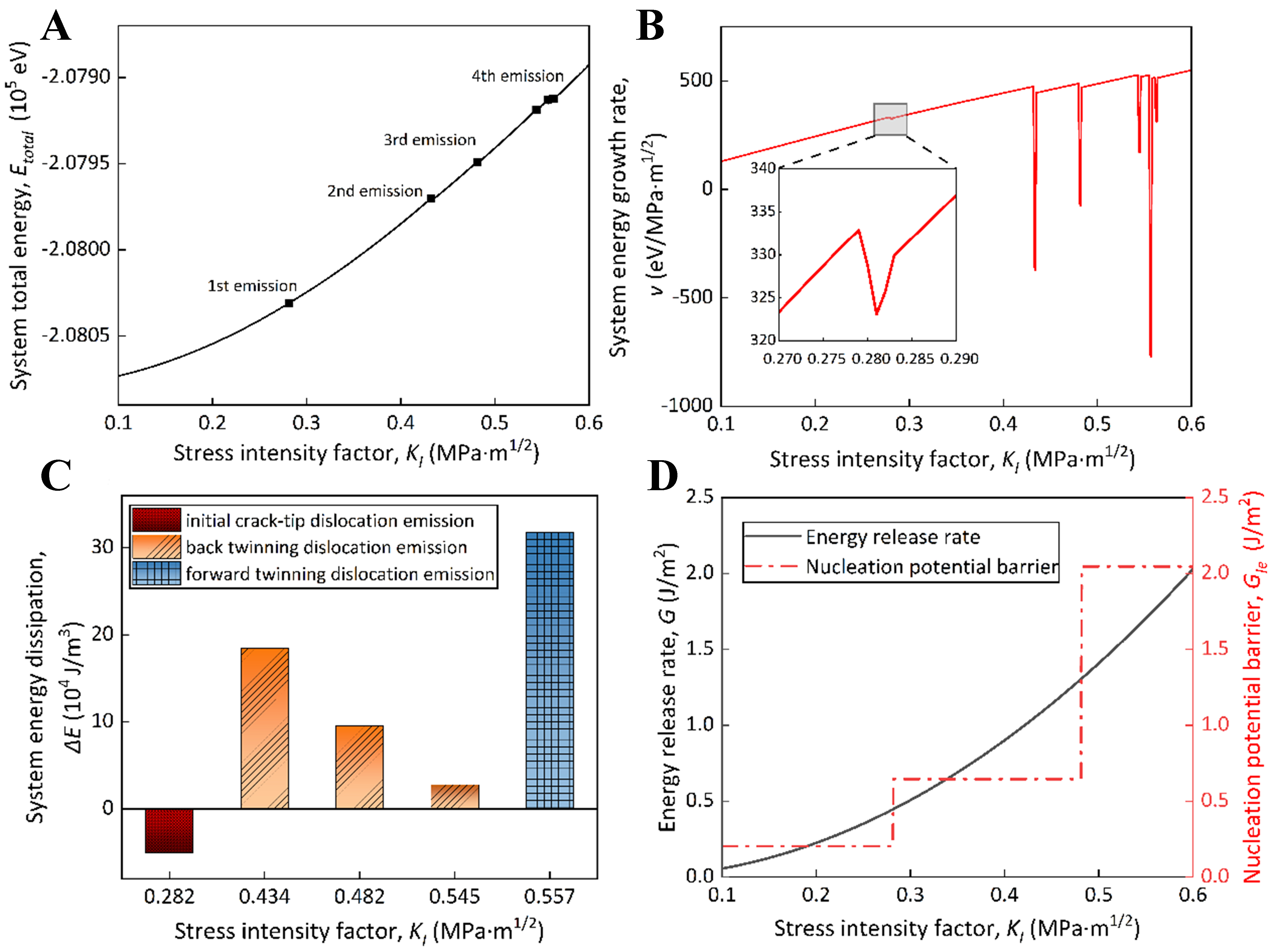
Figure 6. The system energy evolution of FCC Al with a marginal crack under Mode I loading conditions. (A) The system energy evolution; (B) Variations in growth rate of the system energy; (C) Variations in system energy dissipation during emission of different dislocations at the crack tips; and (D) Variations of system energy releasing rate and potential barrier of dislocation nucleation at the crack tips with respect to stress intensity factor. FCC: Faced-centered cubic.
The amount of system released energy during dislocation emission depends on the formation energy of defects at the crack tips. To further understand the dislocation emission behaviors at the crack tips, the energy evolution rule behind key segments for dislocation emission is analyzed, along with the characteristics of variations in potential energy distribution of atoms near the crack tip before and after dislocation emission [Figure 7]. By defining the second derivative of system energy Etotal with respect to the stress intensity factor KI, i.e., α = d2Etotal/dKI2, as the acceleration of system energy evolution, it is found that when KI = 0.281 MPa·m1/2 (corresponding to the first partial dislocation emission), α < 0, indicating the system energy increasing rate slowing down [Figure 7A]. Actually, the rise in system energy is induced by the elevation of potential energy for those atoms near the crack tips. The slowdown for system energy increasing rate signifies that lattice distortion near the crack tips can be released by the SF zone formation, which can restrict the system energy increase further. For dislocation emission dominated by the back twinning dislocation nucleation mechanism [Figure 7B and C], before the second and third partial dislocation emissions at the crack tips, those high-energy atoms can aggregate at the SF zone generated by the first partial dislocation. After the twinning dislocation nucleation, the stratification phenomenon appears for the energy distribution of those atoms near the crack tips. Those atoms within the twinning zone maintain their original high-energy state; however, the energy of those atoms at the twinning boundary becomes lower in comparison to their counterparts within the twinning zone. Thus, the system energy released at the back twinning dislocation nucleation stage originates from the twinning boundary formation. Compared with the second partial dislocation, the third partial dislocation emission is accompanied by a smaller area of twinning boundary, and thus results in less energy release. This is consistent with the analysis in Sections “Characteristics of structural evolution during dislocation emission at the crack tips in FCC Al” and “Atomic displacement criteria for dislocation emission at the crack tips in FCC Al”. For the fourth partial dislocation emission, at the crack tip instability stage, the energy released due to twinning formation is similar to that at the back twinning dislocation nucleation stage [Figure 7D]. Meanwhile, the free surface formation increases the number of high-energy atoms near the crack tips, which slows down the system energy dissipation. When the forward twinning dislocation nucleation enters into the atomic rearrangement stage at the crack tips, the twinning zone expands slightly compared to the crack instability stage. However, the energy dissipates significantly due to the reduced energy of newly added atoms near the crack surface, resulting in an apparent energy decrease compared to previous dislocation emission at the crack tips.
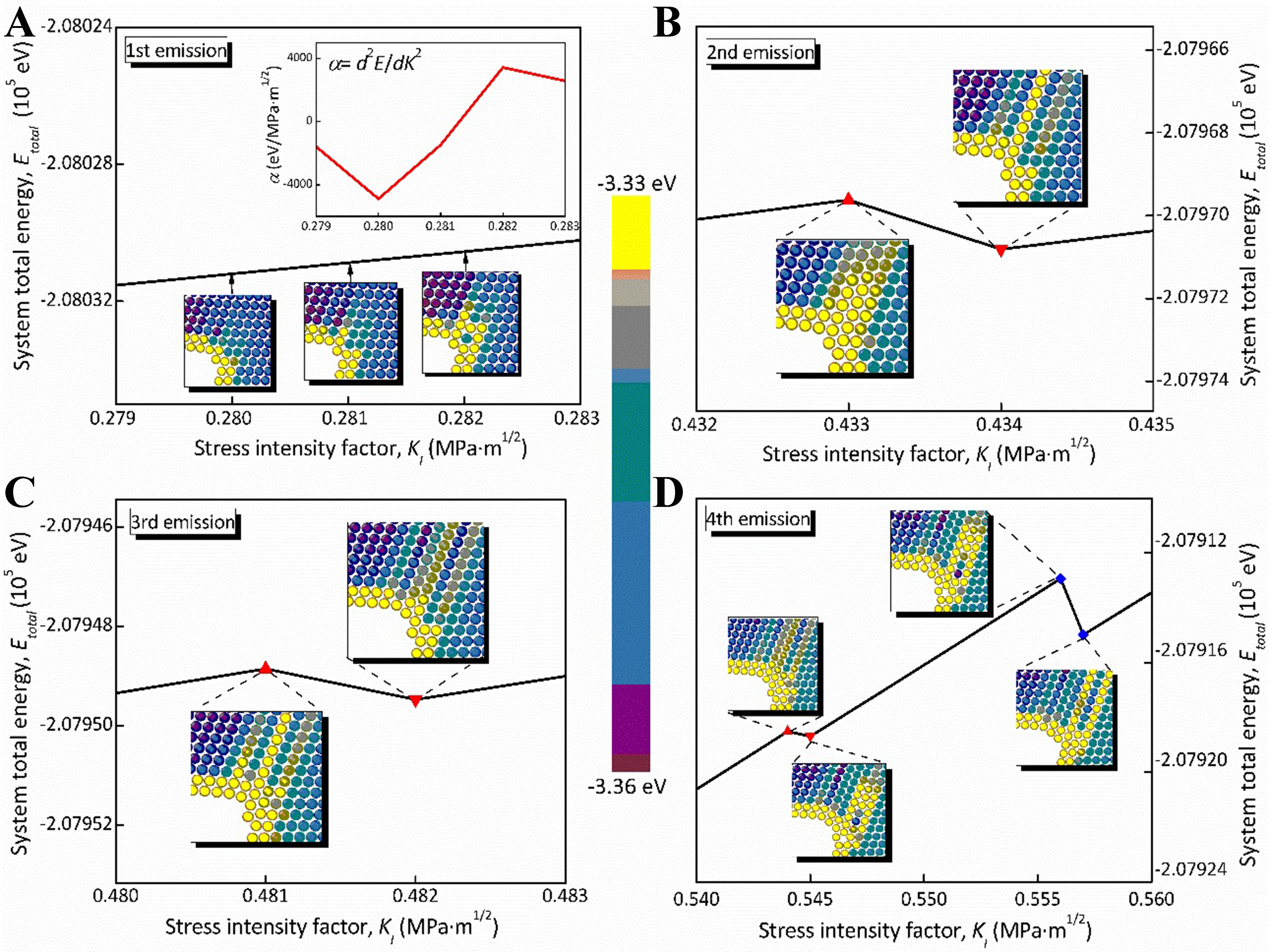
Figure 7. The energy distribution of atoms near the crack tips, as denoted by system energy evolution curve during emission of different dislocations at the crack tips in FCC Al. (A) Emission of the first partial dislocation dominated by the crack-tip nucleation mechanism; (B and C) Emission of the second and third partial dislocations dominated by the back twinning nucleation mechanism; (D) Emission of the fourth partial dislocation dominated by the forward twinning nucleation mechanism. FCC: Faced-centered cubic.
Accordingly, the decrease in system energy evolution rate can serve as a criterion for dislocation emission at the crack tips, while the different mechanisms of dislocation nucleation are determined by the amount of system energy dissipation. For the first partial dislocation nucleation, the system energy remains almost unchanged because there is no rearrangement of atoms near the crack tips. During subsequent back twinning dislocation nucleation at the crack tips, which corresponds to nucleation of the second and third partial dislocations, the SF zone transforms into a twinning zone due to atomic rearrangement, resulting in considerable system energy dissipation. During the forward twinning dislocation nucleation at the crack tips, which corresponds to the fourth partial dislocation nucleation, the system energy dissipates due to the twinning formation and the reduced crack surface derived from atomic rearrangement. This results in multiple peak points in system energy evolution curve, among which the energy decreasing amplitude caused by the surface energy reduction is the largest.
DISCUSSION
Thermo-kinetic criterion for mechanism transition of dislocation nucleation at the crack tips in FCC metals
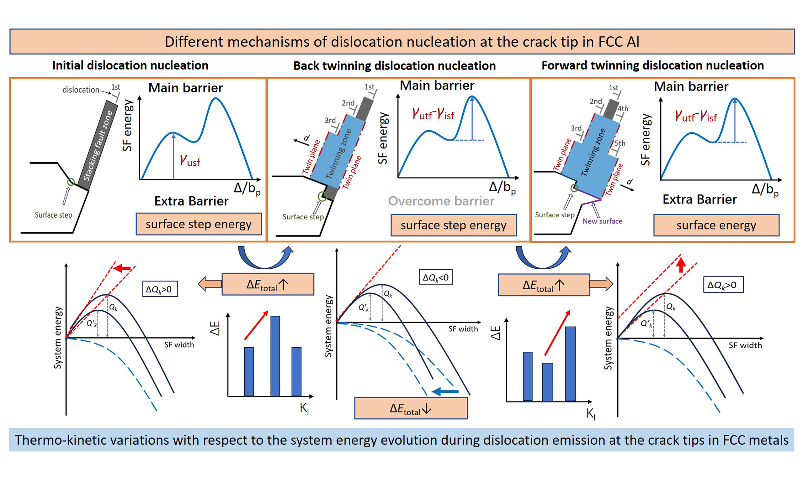
Following the results of Section “Underlying mechanism of dislocation nucleation at the crack tips in FCC Al based on system energy evolution”, the dislocation emission behaviors and the dislocation nucleation mechanism depend on system energy evolution, as dominated by the thermo-kinetic synergy. Specifically, the thermodynamic driving force is provided by the elastic strain energy accumulated at the crack tips, which is proportional to the energy release rate G at the crack tips. In contrast, the thermodynamic resistance is the dislocation nucleation energy Q, which depends on the potential barrier for dislocation nucleation GIe and the distance of dislocation emission (i.e., the SF zone width w). The kinetic energy barrier is determined by the thermodynamic driving force and resistance. The variations in energy release rate G and the potential barrier GIe for dislocation nucleation at the crack tips in FCC Al under the Mode I loading conditions is shown in Figure 6D, where G is obtained from KI based on the Irwin relation[39] (i.e., G = Y·KI2, where Y is the Young’s modulus), while GIe is calculated from the continuum mechanics model[15,27]. As the applied load under the Mode I loading conditions rises, the energy release rate G of dislocation emission grows in a parabolic manner, while the potential barrier for dislocation nucleation GIe increases in a stepwise manner. Notably, GIe can be expressed as a linear combination of the SF energy and surface energy γs:
where γusf, γisf and γutf correspond to the extreme points of the generalized SF energy curve [Figure 8A]. The stages I, II, and III represent the initial crack-tip dislocation nucleation, the back twinning dislocation nucleation, and the forward twin dislocation nucleation, respectively. Under different dislocation nucleation mechanisms [Figure 8B], the dislocation nucleation position and the accompanying defects exert a direct effect on GIe. The potential barrier for dislocation nucleation at different stages can be obtained as: GIe = 0.2038, 0.6458, and 2.046 J/m2 for the initial dislocation nucleation stage, the back twinning dislocation nucleation stage, and the forward twinning dislocation nucleation stage, respectively. Details on calculating potential barrier for dislocation nucleation at the crack tips are provided in the Supplementary Materials.
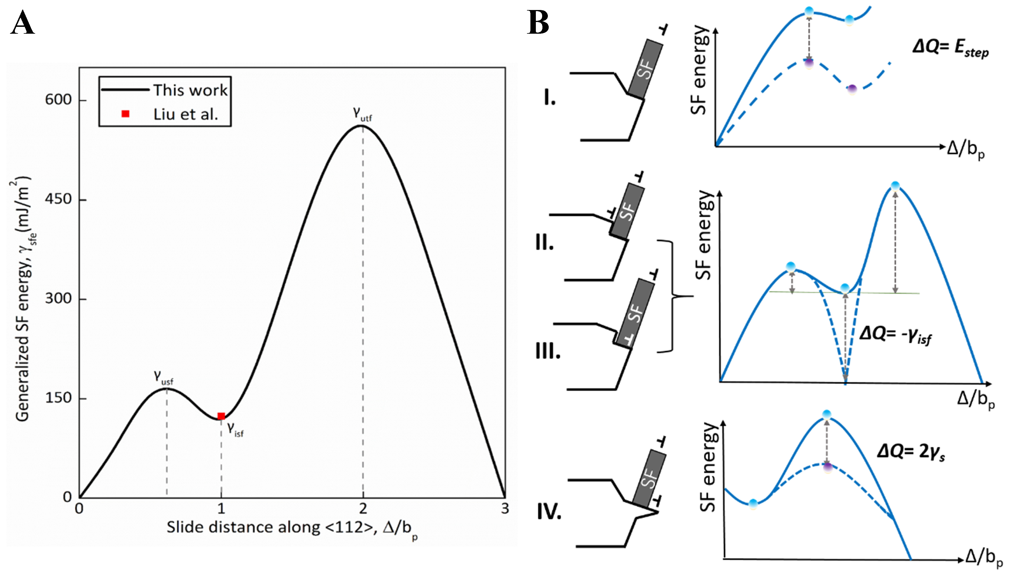
Figure 8. Schematic illustration for correlations between the SF energy γ and the potential barrier GIe of dislocation nucleation at the crack tips in FCC Al. (A) Generalized SF energy curve for FCC Al along the <112> direction on {111} slip plane, where the first peak point, the saddle point, and the second peak point represent the unstable SF energy γusf, intrinsic SF energy γisf, and unstable twinning fault energy γutf, respectively. Note that the values of SF energy calculated in this work are denoted by black solid line, while the red point represents the value reported by Liu et al.[50]; (B) Correlation between dislocation nucleation barrier and position of dislocation nucleation at the crack tips, including (I) dislocation nucleates at the crack tips, where the nucleation barrier GIe increases due to the formation of surface steps, (II and III) dislocation nucleated at the SF region and/or the boundary of the SF region, where the nucleation barrier GIe decreases by γisf, and (IV) dislocation nucleated on a new surface generated after crack instability, where the nucleation barrier GIe increases by 2γs. SF: Stacking fault; FCC: faced-centered cubic.
According to the variations in energy release rate G and potential barrier GIe, the system energy evolution of dislocation emission at the crack tips in FCC metals is schematically illustrated in Figure 9, where the elastic strain energy U accumulated at the crack tips (the blue dashed line) decreases as the SF zone width w increases, while the dislocation nucleation energy Q (the red dashed line) grows linearly with increasing SF region. The synergy of the elastic strain energy U and the dislocation nucleation energy Q determines the system total energy Etotal (the black solid line) to increase firstly and then decrease. When the first derivative of the system total energy Etotal with respect to the SF width w becomes zero, i.e., dEtotal/dw = 0, the system energy evolution reaches a peak point, and the according energy is regarded as the activation energy for dislocation at the crack tips, i.e., the energy barrier Qk of dislocation emission, with its physical meaning analogous to the critical nucleation energy for a new phase during phase transition. When the elastic strain energy U accumulated at the crack tips (i.e., the driving force) equals the energy barrier Qk for dislocation emission, the system has to dissipate energy to reach a stable state, where the amount of released energy ΔE is proportional to dislocation activation energy Qk.
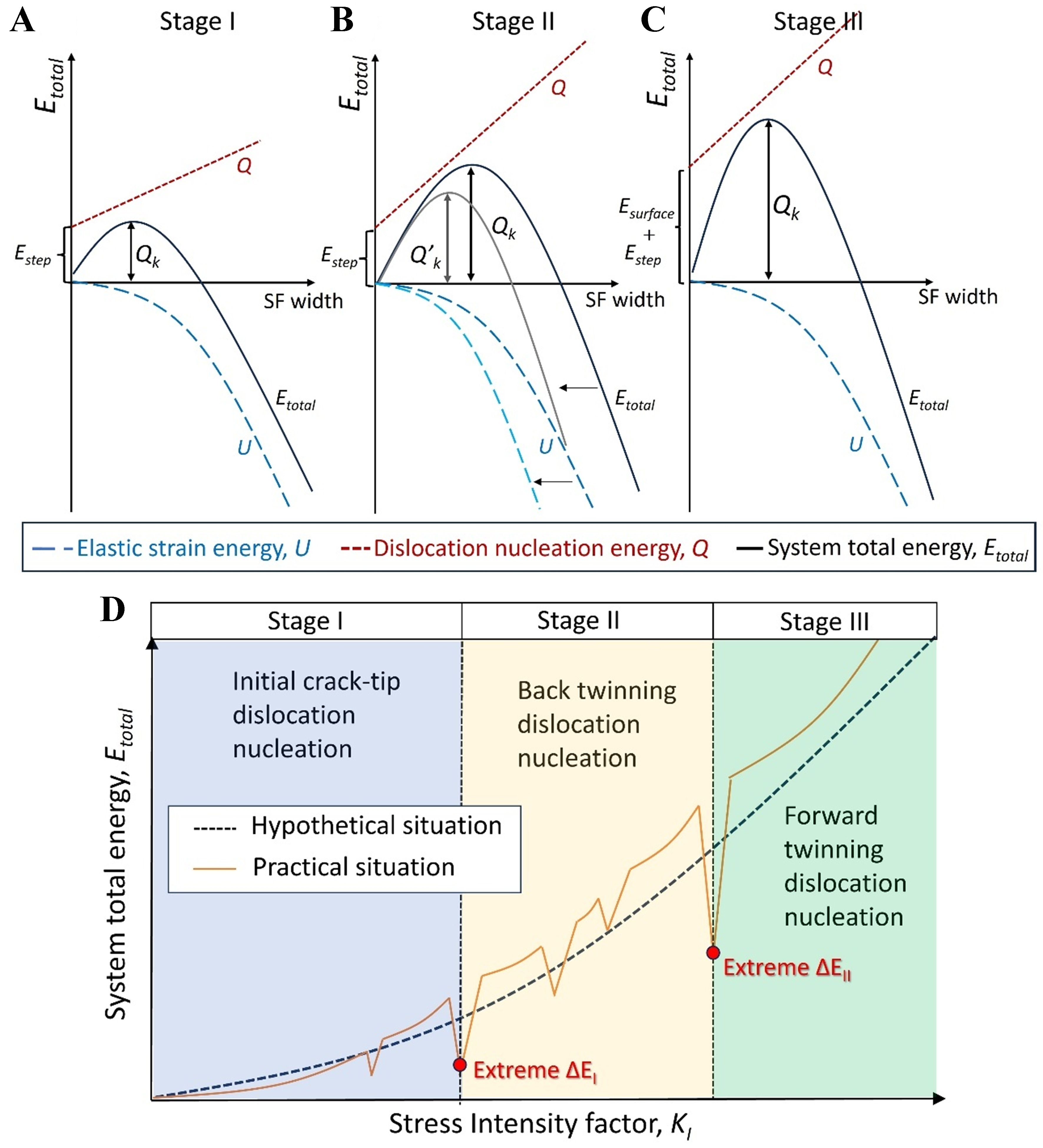
Figure 9. System energy evolution with respect to the stress intensity factor, reflecting the different mechanisms of dislocation nucleation at the crack tips in FCC metals, along with the thermo-kinetic variations during dislocation emission. (A) Nucleation mechanism of the crack-tip dislocation, where the nucleation energy is required to overcome the step formation energy Estep, and subsequently the energy dissipated by the formation of SF zone increases with increasing the width w of SF zone; (B) Nucleation mechanism of the back twinning dislocation, where there is no new surface formation and the intercept of energy axis remains unchanged, although the slope of nucleation energy curve increases with the potential barrier for dislocation nucleation; (C) Nucleation mechanism of the forward twinning dislocation, where there is a new crack surface formation; thus, the nucleation potential barrier requires a surface energy contribution, while the growth rate for dislocation nucleation energy remains the same as that for the back twinning dislocation. Note that the red and blue dashed lines represent the contribution of the nucleation potential barrier as resistance to system total energy, and the contribution of the energy release rate as driving force to system total energy, respectively; (D) System energy evolution with respect to stress intensity factor under Mode I loading conditions, where the dashed line represents the hypothetical situation by assuming the crack tips without dislocation emission and propagation, and the solid line represents the practical situation scenario that there are dislocation emission and propagation at the crack tips. Two peaks appear in the amount of system energy dissipation curve, which corresponds to mechanism transition of dislocation nucleation at the crack tips. Appearance of the first peak indicates the dislocation emission at the crack tips transforming from the first stage (i.e., the initial dislocation nucleation mechanism) to the second stage (i.e., the back twinning dislocation nucleation mechanism), while that of the second peak indicates that dislocation emission steps into the third stage (i.e., the forward twinning dislocation nucleation mechanism). FCC: Faced-centered cubic; SF: stacking fault.
Different dislocation nucleation mechanisms correspond to varying driving forces and energy barriers for dislocation emission, which in turn affect the system energy evolution. For the dislocation crack-tip nucleation mechanism [Figure 9A], the initial value of the dislocation nucleation energy Q originates from the step formation energy Estep. When the nucleation mechanism is dominated by the back twinning dislocation, the rise in potential barrier for dislocation nucleation GIe can cause the curve slope to increase [Figure 9B]. When the mechanism transforms from the back twinning nucleation to the forward twinning nucleation, the contribution associated with the SF zone to the GIe remains unchanged, but the surface energy γs should be overcome, which is reflected as the unchanged slope of the line for Q but an increased intercept along the energy axis [Figure 9C]. It is worthwhile to mention that the energy barrier for dislocation nucleation is associated with the geometric shape of the crack tips and the loading conditions. For instance, the sharp crack tips exhibit a higher nucleation barrier for initial dislocation emission than the blunted crack tips due to the larger difficulty in surface step formation. Besides, the temperature increase can reduce the activation energy for dislocation motion, thus decreasing the dislocation nucleation barrier. Notably, while these factors can influence the critical stress intensity factor for different dislocation nucleation at the crack tips, the fundamental energy evolution rules governing the mechanism transition of dislocation nucleation at the crack tips in FCC Al are not affected.
When the dislocation nucleation mechanism undergoes transition, the elastic strain energy U curve remains unchanged. However, the dislocation nucleation energy suddenly rises with respect to the mechanism transition as follows: (i) the enhanced contribution from SF energy for potential barrier GIe induces a steeper slope of the Q line; (ii) the elevated contribution from surface energy for potential barrier GIe leads to the increase in intercept of the Q line along the energy axis. Accordingly, the energy barrier Qk for dislocation emission escalates in a stepwise manner with respect to the dislocation nucleation mechanism transition, leading to a sudden amplification in energy dissipation ΔE. Figure 6C shows the system energy dissipation during dislocation emission at the crack tips in FCC Al. The amount of system energy dissipation rises from ΔE = -0.5 × 10⁵ to 1.85 × 10⁵ J/m3 when the initial dislocation nucleation stage transforms into the back twinning dislocation nucleation stage. Whereas from the back twinning dislocation nucleation stage to the forward twinning dislocation nucleation stage, ΔE grows from 0.28 × 10⁵ to 3.18 × 10⁵ J/m3. It is noteworthy that the fourth partial dislocation emission at the crack tips in FCC Al belongs to the back twinning dislocation nucleation stage, given that this dislocation emission occurs before atomic rearrangement, while the corresponding defect formation and system energy change characteristics remain similar to those of the back twinning dislocation nucleation, with distinctions in their nucleation location.
When the dislocation emission is dominated by the back twinning nucleation mechanism, there are multiple dislocations successively emitted from the crack tips, while the potential barrier GIe for dislocation nucleation remains unchanged during each dislocation emission [Figure 9B], resulting in a constant dislocation nucleation energy Q. However, the system energy release rate G increases continuously during dislocation emission at the crack tips. According to the expression for system energy release rate[40], i.e., G = -dU/dA, where A represents the area of crack surface, the slope of elastic strain energy curve also rises, with accelerated curve descent rate. This results in the continuous decrease of energy barrier Qk, along with the decrease in width w of SF zone generated by dislocation nucleation at the crack tips. The decrease in Qk corresponds to the gradual decrease in the amount of system energy dissipation ΔE [Figure 6D], where the energy release rate G associated with the driving force for dislocation emission increases from U = 0.44 to 1.30 J/m2 during emission of the second, third, and fourth partial dislocations (all dominated by the back twinning dislocation nucleation) at the crack tips in FCC Al, while the ΔE associated with Qk for dislocation emission decreases from 1.85 × 10⁵ to 0.28 × 10⁵ J/m3. Hence, the increase in driving force U for dislocation emission at the crack tips in FCC Al is accompanied by the decrease in energy barrier Qk, thus promoting dislocation emission, which is manifested as the reduced interval for dislocation emission at the crack tips. These analyses are in accordance with the results of Section “Atomic displacement criteria for dislocation emission at the crack tips in FCC Al” regarding the increment of applied load required for different dislocation emission [Figure 5D].
Following the above analysis, the correlation between different dislocation nucleation mechanisms and the system energy evolution during dislocation emission at the crack tips in FCC metals is schematically illustrated in Figure 9D. Under the Mode I loading conditions, the system energy evolution curve exhibits an overall parabolic upward trend, but there are several abrupt points (where the system energy firstly drops and then rises), which corresponds to the dislocation emission. As such, the dislocation nucleation mechanism transition can be examined in combination with the amount of system energy dissipation at the dislocation emission points. As shown in Figure 6C and 9D, when the dislocation nucleation mechanism transforms from the initial crack-tip nucleation (Stage I) to the subsequent back twinning nucleation (Stage II) and the forward twinning nucleation (Stage III), the amount of system energy dissipation increases progressively. Meanwhile, the sequential emission of multiple dislocations appears in the back twinning dislocation nucleation stage, where each dislocation emission is accompanied by gradual decrease in the amount of system energy dissipation. The system energy dissipation associated with dislocation emission at the crack tips can be treated as a discrete function of the stress intensity factor. Considering that there are three dislocations sequentially emitted at the crack tips with the corresponding stress intensity factor as Kn-1, Kn and Kn+1, when the system energy dissipation E(K) associated with these emission events satisfies: E(Kn) > E(Kn+1) and E(Kn) > E(Kn-1), and then Kn marks the critical stress intensity factor for the mechanism transition of dislocation nucleation at the crack tips in FCC metals [Figure 9D].
Before crack-tip instability, the number of dislocations emitted at the crack tips is restricted. As such, the fracture toughness can be adjusted by regulating the difficulty or ease of dislocation emission at the crack tips. In combination with system energy evolution, the process of dislocation emission can be slowed down by reducing the driving force (elastic strain energy U) and/or increasing the energy barrier Qk for dislocation emission, and thus the dislocation emission interval decreases. This is favorable for delaying fracture so as to enhance the fracture toughness. For example, the intrinsic SF energy γisf of Al alloys can be decreased by adding alloying elements[41] such as Cu, Mg, and Si, which can enhance the energy difference between the peak and saddle points on the generalized SF energy curve, corresponding to an increase in the potential barrier GIe for dislocation nucleation at the crack tips. Thus, the energy barrier Qk for dislocation emission can be enhanced, which makes the dislocation emission slower and more sustainable, thus delaying the crack propagation.
It is noteworthy that the present thermo-kinetic criterion for dislocation emission behaviors and dislocation nucleation mechanisms of FCC Al can be extended to other FCC metals. The distinctions lie in the magnitude of driving force and energy barrier for dislocation emission at the crack tips of different FCC metals, which is attributed to the differences in their characteristics of SF energy and surface energy[42]. Furthermore, it is certain that other defects can affect the dislocation emission behaviors at the crack tips of FCC metals. For instance, the solute atoms exert influences by changing the SF energy with respect to potential barrier of dislocation nucleation at the crack tips[43]. The existence of grain boundary can serve as a pathway for crack propagation, and thus affect the deformation mechanisms at the crack tips[44]. The precipitates that existed along the dislocation emission direction can introduce additional energy barriers for dislocation motion[45]. Accordingly, the design for high-toughness FCC metallic alloys can be achieved by adjusting composition/processing dependent thermo-kinetic synergy during dislocation emission at the crack tips in FCC metals[46-49]. Our continuous investigations along these directions are still in progress to acquire the general rule for dislocation nucleation with respect to the critical conditions for dislocation emission at the crack tips in FCC metallic alloys, and the results will be reported in further work.
CONCLUSIONS
In summary, this work investigates the dislocation emission behaviors at the crack tips in FCC Al under Mode I loading conditions based on a continuum mechanics model within the ALEFM framework and MD simulations. The characteristics of defect structures and the system energy evolution rule during dislocation emission at the crack tips were clarified. A thermo-kinetic criterion for the critical condition of dislocation emission and mechanism transition of dislocation nucleation at the crack tips was proposed. The following conclusions can be drawn:
(i) The system energy of FCC Al with marginal cracks gradually increases with the stress intensity factor KI. However, the system energy suddenly drops once a dislocation is emitted at the crack tips. The dislocation emission process can be classified into three stages, including the initial dislocation nucleation stage, the back twinning dislocation nucleation stage, and the forward twinning dislocation nucleation stage. The first partial dislocation nucleation is accompanied by the formation of SF zone and the appearance of surface steps, with the system energy variation being ΔE = 0.5 × 10⁵ J/m3. The second partial dislocation emission is dominated by the back twinning nucleation mechanism, which is accompanied by the formation of twinning zone and triggers the energy dissipation further, with the system energy variation decreasing to ΔE = -1.85 × 10⁵ J/m3. The fourth partial dislocation emission is accompanied by the merge of new crack surfaces, with the system energy variation decreasing to ΔE = -3.18 × 10⁵ J/m3, which marks the dislocation emission at the crack tips entering into the forward twinning nucleation stage.
(ii) The amount of system energy dissipation ΔE, which is dominated by the energy barrier Qk for dislocation emission, can serve as the criterion for the mechanism transition of dislocation nucleation at the crack tips. The value of Qk for the crack-tip dislocation emission is regarded as the maximum energy difference between the elastic strain energy U at the crack tips and the dislocation nucleation energy Q with respect to the SF zone width w. The system energy has to be released to maintain its stability once the system energy rises to Qk, which signifies the positive correlation between ΔE and Qk. The potential barrier of dislocation nucleation (i.e., the critical energy release rate GIe) undergoes a sudden change when the mechanism transition of dislocation nucleation at the crack tips occurs. The value of GIe for the initial dislocation nucleation stage, the back twinning dislocation nucleation stage, and the forward twin dislocation nucleation stage is 0.2038, 0.6458, and 2.046 J/m2, respectively. The corresponding dislocation nucleation energy Q increases progressively, while the driving force (i.e., the elastic strain energy) cannot keep up with the variation in Q, leading to progressive increases in both Qk and ΔE. When the stress intensity factor increases from KI = 0.434 to 0.545 MPa·m1/2 during dislocation emission dominated by the back twinning nucleation mechanism, there are multiple dislocations emitted sequentially at the crack tips, with GIe remaining unchanged as 0.6458 J/m2. While the energy release rate (associated with the driving force for dislocation emission) increases from G = 0.44 to 1.30 J/m2, causing the gradual decrease in both Qk and ΔE. Accordingly, ΔE reaches a maximum value when the dislocation nucleation mechanism transforms during dislocation emission, based on which the mechanism transition of dislocation nucleation at the crack tips can be determined.
Our investigations provide an innovative perspective to understand the dislocation emission behaviors at the crack tips in FCC metals from the thermo-kinetic synergy, and thus offer an insightful guidance for improving the fracture toughness of metallic alloys with FCC structures.
DECLARATIONS
Authors’ contributions
Conceptualization, supervision: Du, J.; Liu, F.
Investigation, writing original draft: Zhang, K.; Du, J.; Xiao, J.
Writing, review and editing: Zhang, K.; Du, J.; Xiao, J.; Song, K.; Liu, F.
Investigation, methodology, discussion: Zhang, K.; Du, J.; Xiao, J.; Yang, Z.; Yang, J.
Funding acquisition: Du, J.; Liu, F.
Availability of data and materials
The data that support the findings of this study are available from the corresponding author upon reasonable request.
Financial support and sponsorship
This work is financially supported by the National Natural Science Foundation of China (Grant Nos. 52171013, and 52130110), the Key Research and Development Program of Shaanxi (Grant No. 2025CY-YBXM-127), the Natural Science Foundation of Chongqing (Grant No. CSTB2022NSCQMSX0369), and the Research Fund of the State Key Laboratory of Solidification Processing (NPU) China (Grant No. 2023-QZ-03). The authors acknowledge the Analytical & Testing Center and the High-Performance Computing Center of NPU for access to supercomputing facilities.
Conflicts of interest
All authors declared that there are no conflicts of interest.
Ethical approval and consent to participate
Not applicable.
Consent for publication
Not applicable.
Copyright
© The Author(s) 2025.
Supplementary Materials
REFERENCES
1. Salvado, F. C.; Teixeira-Dias, F.; Walley, S. M.; Lea, L. J.; Cardoso, J. B. A review on the strain rate dependency of the dynamic viscoplastic response of FCC metals. Prog. Mater. Sci. 2017, 88, 186-231.
2. Li, H.; Ebrahimi, F. Transition of deformation and fracture behaviors in nanostructured face-centered-cubic metals. Appl. Phys. Lett. 2004, 84, 4307-9.
3. He, B. B.; Hu, B.; Yen, H. W.; et al. High dislocation density-induced large ductility in deformed and partitioned steels. Science 2017, 357, 1029-32.
4. Li, H.; Du, J.; Shang, S.; Liu, Z.; Liu, F. 3D misfit potentials dependent deformation behaviors with respect to different dislocation core structures of fcc metals. Phys. Rev. Mater. 2025, 9, 063604.
5. Paul, M. J.; Kruzic, J. J.; Ramamurty, U.; Gludovatz, B. The importance of fracture toughness evaluation for additively manufactured metals. Acta. Mater. 2024, 276, 120061.
6. Carlsson, A. E.; Thomson, R. Fracture toughness of materials: from atomistics to continuum theory. Solid. State. Phys. 1998, 51, 233-80.
7. Ma, J.; Yuan, L.; Zong, Y.; Zheng, M.; Shan, D.; Guo, B. Crack-tip cleavage/dislocation emission competition behaviors/mechanisms in magnesium: ALEFM prediction and atomic simulation. Int. J. Plast. 2024, 182, 104134.
8. Armstrong, R. Cleavage crack propagation within crystals by the Griffith mechanism versus a dislocation mechanism. Mater. Sci. Eng. 1966, 1, 251-4.
10. Rice, J. R.; Thomson, R. Ductile versus brittle behaviour of crystals. Philos. Mag. 1974, 29, 73-97.
12. Rice, J. R. Dislocation nucleation from a crack tip: an analysis based on the Peierls concept. J. Mech. Phys. Solids. 1992, 40, 239-71.
14. Brocks, W. Elastic-plastic fracture mechanics. In Plasticity and Fracture. Cham: Springer International Publishing; 2018. pp. 49-84.
15. Andric, P.; Curtin, W. New theory for Mode I crack-tip dislocation emission. J. Mech. Phys. Solids. 2017, 106, 315-37.
16. Xu, G.; Argon, A. S.; Ortiz, M. Nucleation of dislocations from crack tips under mixed modes of loading: implications for brittle against ductile behaviour of crystals. Philos. Mag. A. 1995, 72, 415-51.
17. Gumbsch, P.; Beltz, G. E. On the continuum versus atomistic descriptions of dislocation nucleation and cleavage in nickel. Model. Simul. Mater. Sci. Eng. 1995, 3, 597-613.
18. Kelly, A.; Tyson, W. R.; Cottrell, A. H. Ductile and brittle crystals. Philos. Mag. 1967, 15, 567-86.
19. Schoeck, G. The emission of dislocations from crack tips. Mater. Sci. Eng. A. 2003, 356, 93-101.
20. Schoeck, G. Dislocation emission from crack tips as a variational problem of the crack energy. J. Mech. Phys. Solids. 1996, 44, 413-37.
21. Zamora, R. J.; Nair, A. K.; Hennig, R. G.; Warner, D. H.
22. Tadmor, E.; Hai, S. A Peierls criterion for the onset of deformation twinning at a crack tip. J. Mech. Phys. Solids. 2003, 51, 765-93.
23. Yamakov, V.; Warner, D.; Zamora, R.; Saether, E.; Curtin, W.; Glaessgen, E. Investigation of crack tip dislocation emission in aluminum using multiscale molecular dynamics simulation and continuum modeling. J. Mech. Phys. Solids. 2014, 65, 35-53.
24. Knap, J.; Sieradzki, K. Crack tip dislocation nucleation in FCC solids. Phys. Rev. Lett. 1999, 82, 1700-3.
25. He, X.; Zhang, W.; Li, X. Modeling of Mode I crack-tip dislocation nucleation in three FCC materials: Ni, Cu and Al. Mech. Mater. 2024, 196, 105068.
26. Van Swygenhoven, H.; Derlet, P.; Frøseth, A. Nucleation and propagation of dislocations in nanocrystalline fcc metals. Acta. Mater. 2006, 54, 1975-83.
27. Andric, P.; Curtin, W. New theory for crack-tip twinning in fcc metals. J. Mech. Phys. Solids. 2018, 113, 144-61.
29. Andric, P.; Curtin, W. A. Atomistic modeling of fracture. Model. Simul. Mater. Sci. Eng. 2019, 27, 013001.
30. Argon, A. S.; Xu, G.; Ortiz, M. Kinetics of dislocation emission from crack tips and the brittle to ductile transition of cleavage fracture. MRS. Online. Proc. Libr. 1995, 409, 29-44.
31. Gulizzi, V.; Benedetti, I.; Milazzo, A. A novel boundary element formulation for anisotropic fracture mechanics. Theor. Appl. Fract. Mech. 2019, 104, 102329.
32. Zhu, S.; Ringer, S. P. On the role of twinning and stacking faults on the crystal plasticity and grain refinement in magnesium alloys. Acta. Mater. 2018, 144, 365-75.
34. Mishin, Y.; Farkas, D.; Mehl, M. J.; Papaconstantopoulos, D. A. Interatomic potentials for monoatomic metals from experimental data and ab initio calculations. Phys. Rev. B. 1999, 59, 3393.
35. Du, J.; Liu, Y.; Zhao, C.; et al. Towards mechanical performance paradox and behind thermo-kinetic origins of aluminum alloys with additional solutes (X = Mg, Cu and Si) from atomistic simulations. J. Mater. Inf. 2025, 5, 10.
36. Bitzek, E.; Koskinen, P.; Gähler, F.; Moseler, M.; Gumbsch, P. Structural relaxation made simple. Phys. Rev. Lett. 2006, 97, 170201.
37. Brunner, F.; Andric, P.; Maresca, F. An atomistic K-test framework for general grain boundaries and triclinic single crystals. Model. Simul. Mater. Sci. Eng. 2025, 33, 035004.
38. Kou, Z.; Yang, Y.; Yang, L.; Zhang, W.; Huang, B.; Luo, X. Deformation twinning in response to cracking in Al: an in situ TEM and molecular dynamics study. Scr. Mater. 2018, 145, 28-32.
39. Yarema, S. Y. On the contribution of G. R. Irwin to fracture mechanics. Mater. Sci. 1996, 31, 617-23.
40. Griffith, A. A. VI. The phenomena of rupture and flow in solids. Phil. Trans. R. Soc. Lond. A. 1921, 221, 582-93.
41. Du, J.; Liu, Y.; Zhang, Z.; et al. Deformation behaviors in light of dislocation core characteristics with respect to the compositional-dependent misfit potentials of aluminum alloys. J. Mater. Res. Technol. 2023, 27, 4366-77.
42. Zhang, Z.; Li, K.; Cai, T.; et al. Effects of stacking fault energy on the deformation mechanisms and mechanical properties of face-centered cubic metals. Acta. Metall. Sin. 2023, 59, 467-77 (in Chinese).
43. Ren, S.; Li, J.; Fang, Q.; Feng, H. Effect of solid solution addition on the dislocation emission in aluminum alloys. Acta. Mech. 2020, 231, 4537-45.
44. Sheng, Y.; Yang, H.; Ma, W.; Jiang, X. Interaction of dislocations and cracks in grains based on discrete dislocations. Int. J. Fract. 2023, 239, 135-47.
45. Zeng, G.; Guo, Y.; Xiong, C.; et al. Enhanced fatigue crack propagation resistance of Al-Cu-Li alloys via regulating grain structure and precipitation behavior. Int. J. Fatigue. 2025, 197, 108916.
46. Lu, Z.; Kapoor, I.; Li, Y.; Liu, Y.; Zeng, X.; Wang, L. Machine learning driven design of high-performance Al alloys. J. Mater. Inf. 2024, 4, 19.
47. Liu, J.; Sun, J.; Meng, J.; Li, J. Microstructural stability and stress rupture properties of a third-generation Ni base single crystal supalloy. Acta. Metall. Sin. 2024, 60, 770-6 (in Chinese).
48. Wang, K.; Li, H.; Zhou, Y.; Wang, J.; Xin, R.; Liu, Q. Dislocation slip and crack nucleation mechanism in dual-phase microstructure of titanium alloys: a review. Acta. Metall. Sin. 2023, 36, 353-65.
49. Tan, K.; Xie, J.; Qin, H.; et al. Effects of Co and Nb on the crack of additive manufacturing nickel-based superalloys. Acta. Metall. Sin. 2024, 37, 1601-10.
Cite This Article
How to Cite
Download Citation
Export Citation File:
Type of Import
Tips on Downloading Citation
Citation Manager File Format
Type of Import
Direct Import: When the Direct Import option is selected (the default state), a dialogue box will give you the option to Save or Open the downloaded citation data. Choosing Open will either launch your citation manager or give you a choice of applications with which to use the metadata. The Save option saves the file locally for later use.
Indirect Import: When the Indirect Import option is selected, the metadata is displayed and may be copied and pasted as needed.
About This Article
Copyright

Data & Comments
Data
0


Comments
Comments must be written in English. Spam, offensive content, impersonation, and private information will not be permitted. If any comment is reported and identified as inappropriate content by OAE staff, the comment will be removed without notice. If you have any queries or need any help, please contact us at [email protected].