fig2

Atomistic underpinnings for dislocation emission behaviors at the crack tips in FCC metals in light of thermo-kinetic synergy

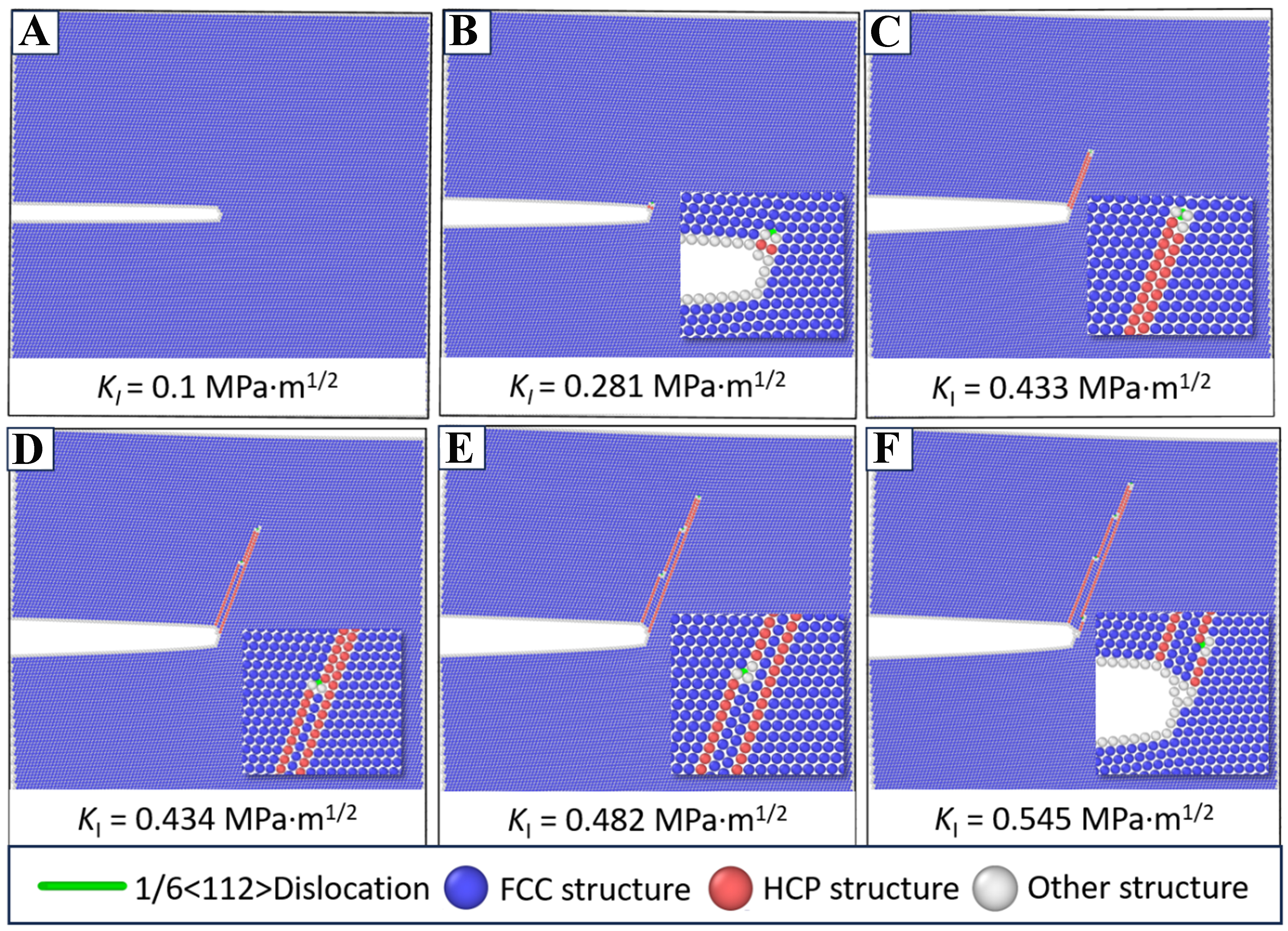
Figure 2. Snapshots for evolution of atomic configurations along the direction perpendicular to [$$ \bar{1} $$10] of FCC Al with a marginal crack under the Mode I loading conditions. (A) The initial atomic configuration of the marginal crack; (B and C) The atomic configurations at stress intensity factor of KI = 0.281 and 0.433 MPa·m1/2, respectively, which correspond to the nucleation and emission of the first partial dislocation at the crack tips; (D and E) The atomic configurations at stress intensity factors of KI = 0.434 and 0.482 MPa·m1/2, respectively, which correspond to the second and third partial dislocation emission at the crack tips; (F) The atomic configuration at stress intensity factor of KI = 0.545 MPa·m1/2, which corresponds to the fourth partial dislocation emitted from the propagation plane at the front of crack tips. Note that the green line represents the 1/6<112> Shockley partial dislocation. The atomic configurations are denoted by the CNA, where the blue, red and white atoms represent the FCC, HCP and other structures, respectively. FCC: Faced-centered cubic; CNA: common neighbor analysis; HCP: hexagonal-close packed.

Journal of Materials Informatics
ISSN 2770-372X (Online)
Follow Us

Portico

All published articles are preserved here permanently:

https://www.portico.org/publishers/oae/

Portico

All published articles are preserved here permanently:

https://www.portico.org/publishers/oae/