


fig12
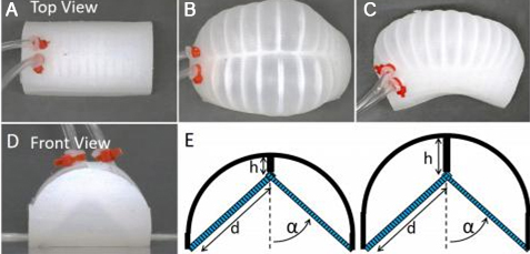
Figure 12. (A-C) are top views of the actuator, showing structural morphologies under different working states: (A) Initial flat state without air pressure input, where the silicone matrix maintains natural relaxation; (B) Asymmetric bending state after inflation of a single-side chamber, with the strain-limiting layer (blue pattern) restricting local deformation to induce bending of the actuator to one side; (C) Transitional deformation state after alternating inflation of bilateral chambers, preparing for axial propulsion; (D) Front view of the actuator, clearly presenting the layered structure of the silicone matrix and the strain-limiting layer; (E) presents a simplified model of the actuator with varying parameters. The blue pattern indicates the strain-limiting layer. Adapted with permission[14], Copyright 2019, IEEE.


