


Graphene-based flexible magnetic tactile sensor with vertically periodic magnetization for enhanced spatial resolution
 0
0 Abstract
This study presents the design and implementation of a fully flexible, high-resolution magnetic tactile sensor that integrates a vertically periodic magnetized film with a 3 × 3 flexible Hall sensor array. To achieve optimal mechanical flexibility and electrical performance, graphene was employed as the active sensing material, and polyethylene terephthalate was chosen as the substrate, based on a comprehensive evaluation of carrier mobility, material thickness, mechanical compliance, and fabrication compatibility. The incorporation of a vertically periodic magnetization strategy in the magnetic film effectively suppressed lateral magnetic field interference and improved surface magnetic flux concentration. This architectural approach enabled spatial position recognition to be enhanced from 3 × 3 to 6 × 6 sensing units. The fabricated sensor exhibited robust performance, achieving an average sensitivity of 0.13 mV/N, a linearity coefficient of 0.97, and a hysteresis rate of 11.4%, demonstrating its potential for high-performance tactile sensing in flexible electronic systems.
Keywords
INTRODUCTION
In recent years, tactile sensors have demonstrated significant application potential in various fields, including tactile perception[1], fingerprint recognition[2], medical monitoring[3,4], human-machine interfaces[5], and the Internet of Things[6]. In wearable health monitoring systems, tactile sensors can continuously track physiological signals such as pulse, heart rate, and respiration[7], thereby offering technological support for medical and remote health monitoring applications. By integrating multiple sensing capabilities into robotic systems, robots are enabled to perceive and process environmental information in real time, facilitating effective interaction with humans in complex scenarios. Among these capabilities, tactile perception plays an irreplaceable role in enhancing a robot’s adaptability to its surroundings and precision in manipulating target objects1. Tactile sensors not only serve as input interfaces between users and devices, but also provide real-time feedback, thereby improving the overall interaction experience and the level of system intelligence.
To date, different sensing types of tactile sensors, including magnetic[8-16], piezoresistive[17-19], and capacitive[20-22] sensors, have been developed. Magnetic tactile sensors can provide rich information dimensions, extracting force information including magnitude, direction and position through magnetic field information in three directions. Moreover, magnetic tactile sensors have higher stability and lower hysteresis than resistive types, better linearity than capacitive types, a wider range of force types than piezoelectric types, and are less susceptible to external environmental influences than optical types[23-25]. Finally, magnetic tactile sensors have the advantages of a simple structure and ease of use.
Currently, numerous studies have explored the position-sensing performance of magnetic tactile sensors. For instance, Yan et al. developed a 3 × 3 Hall sensor array for coarse localization and used deep learning to boost spatial resolution by 60 times for fine-grained positioning, enabling tasks such as stable fragile object grasping and needle threading[26]. They later[27] proposed a super-resolution method based on sinusoidally magnetized soft magnetic skin, improving localization accuracy from 6 to 0.4 mm (a 15-fold increase) and enabling force measurement, with the model relying on single triaxial sensor pixel local information for robust multi-point contact detection even with damaged neighboring pixels. Hu et al. designed a wireless flexible magnetic tactile sensor with a multi-directionally magnetized film and non-contact Hall element, achieving high-resolution position detection (≈ 3,600 mm2, 2.1 mm average error, 30 mm sensing distance) via specific magnetization, Kriging interpolation, and clustering[28]. Their subsequent work[29] introduced another magnetic skin with a multi-directionally magnetized film and a 4 × 4 Hall array, achieving super-resolution perception over 48,400 mm2 (1.2 mm average error) using tailored magnetization, K-nearest neighbors (KNN), and convolutional neural networks (CNN). Wu et al. achieved high-resolution tactile sensing from low-resolution sensors via multiple sampling, CNN, generative adversarial networks (GAN), and a novel dataset, enhancing the resolution 100-fold (from 4 × 4 to 40 × 40 grid)[30]. However, most of these studies utilized commercial rigid Hall sensors. Flexibility is crucial for tactile sensing to conform to human skin or robotic surfaces. While magnetic films are flexible, Hall sensors themselves usually lack flexibility. Researchers often combine commercial triaxial Hall sensors with custom magnetic films[26,31,32], but this leads to non-fully flexible tactile sensors, limiting applications in soft electronic skins and robotics. To date, no work has reported position sensing using flexible Hall sensors in magnetic tactile systems. Thus, achieving both flexibility and spatial position sensing remains a key challenge.
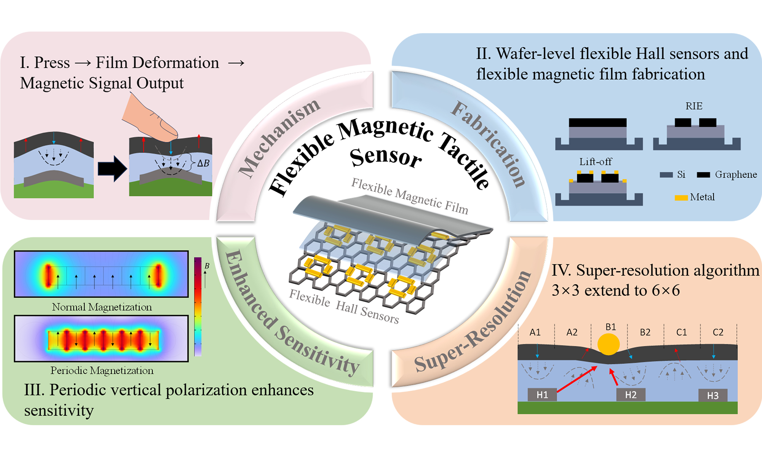
In this work, a fully flexible, high-resolution magnetic tactile sensor is developed through a systematic investigation of Hall sensor design and magnetic film configuration. A flexible Hall sensor was designed and fabricated using micro-electro-mechanical system (MEMS) technology. Through a comprehensive comparison of key material parameters - including carrier mobility, thickness, mechanical flexibility, and fabrication compatibility - appropriate materials were selected for the active sensing region and substrate, ensuring an optimal balance between electrical performance and mechanical compliance. To enhance spatial position-sensing capability, a magnetic tactile sensor architecture is proposed that integrates a Hall sensor array with a vertically periodic magnetized film. The array configuration was optimized through a trade-off between signal processing complexity and sensing accuracy. Moreover, the introduction of vertically periodic magnetization in the magnetic film effectively suppresses lateral magnetic field interference while enhancing the concentration of the surface magnetic flux. With this design, the fabricated sensor achieves full flexibility alongside high-resolution spatial position detection, demonstrating strong potential for integration in advanced flexible electronic systems.
EXPERIMENTAL
Fabrication for flexible Hall sensors
Graphene Hall sensors were fabricated on transferred graphene using microfabrication techniques based on electron-beam (E-beam) lithography, as detailed in Supplementary Figure 1. The fabrication process began with the patterning of a cross-shaped graphene channel via E-beam lithography, followed by oxygen plasma etching to define the active sensing region. Metal contacts were subsequently patterned using E-beam lithography on a photoresist layer, followed by development. A Ti/Al (10/500 nm) bilayer was deposited using E-beam evaporation, and a standard lift-off process was employed to complete the contact formation. The resulting device exhibits a symmetric cross-like geometry with four electrodes and high-quality graphene with minimal defects, as shown in Supplementary Figure 2A and B. To protect the graphene channel from environmental contaminants and improve device stability under ambient conditions, a 1 μm-thick parylene-C passivation layer was deposited, as shown in Supplementary Figure 4.
Fabrication of magnetic films
The preparation process for the magnetic film is illustrated in Supplementary Figure 5. Dragon Skin 10 NV (Smooth-On, Inc., Macungie, Pennsylvania, United States), a low-viscosity, addition-cure silicone rubber known for its mechanical robustness, was selected as the flexible matrix material. Neodymium-iron-boron (NdFeB) powder, with an average particle diameter of 38 μm, was incorporated due to its superior magnetic properties, including high remanence and coercivity. The fabrication process involved mixing the A and B components of Dragon Skin 10 NV in a 1:1 mass ratio, followed by the addition of NdFeB powder. The mixture was thoroughly stirred and cast onto a glass substrate. A film applicator was used to uniformly spread the mixture into a thin film, which was then cured at room temperature. Once fully cured, the film was laser-cut into the desired shape and dimensions. Magnetization was carried out using a local pulse magnetization technique, wherein a 1 mm magnetization head was employed to alternately magnetize the film with north (N) and south (S) poles in a vertically periodic pattern.
Test system
The experimental setup, as illustrated in Supplementary Figure 6, consists of a three-axis sliding platform, a three-axis force sensor, a 3D-printed indenter head (3 mm in diameter), a power supply, a data acquisition (DAQ) card, and a computer. The three-axis force sensor is mounted on the movable end of the sliding platform, with the 3D-printed head affixed to its bottom. The tactile sensor under test is securely mounted on an optical platform. The power supply and DAQ card are connected to the input and output terminals of the tactile sensor, respectively. An operational amplifier with a gain of 20× is inserted between the tactile sensor and the DAQ card to enhance the signal. Once assembled, the system allows precise control of the movement direction and displacement of the sliding platform via a control unit or computer interface. During testing, the indenter contacts the tactile sensor and applies a controlled force, while the force sensor simultaneously records the applied force components. Concurrently, the DAQ card captures the voltage response of the tactile sensor. By correlating the recorded force and output voltage data, the sensor’s electromechanical response characteristics can be quantitatively evaluated.
RESULTS AND DISCUSSION
Tactile sensor design
As shown in Figure 1A, the tactile sensor adopts a bioinspired multilayered structure mimicking human skin, comprising four functional layers. The top layer uses a flexible magnetic film (composite of dragon skin 10 NV and NdFeB particles) with magnetically printed 2D periodically polarized orientations to enhance surface magnetic fields. The intermediate layer consists of a 0.5 mm-thick Ecoflex 00-30 elastomer serving as a compliant medium to facilitate mechanical deformation, thereby amplifying magnetic field variations. The bottom two layers form a 3 × 3 flexible graphene-based Hall sensor array. The fully flexible Hall sensor structure conforms well to irregular surfaces, enabling its application scenarios on complex geometries such as human or robotic fingers. Figure 1B and C illustrates that when the tactile sensor is subjected to external force, deformation occurs in the flexible magnetic film, causing displacement of embedded permanent magnetic particles. This subsequently alters the local magnetic flux density beneath the film. Hall sensors detect these variations through the Hall effect and generate corresponding Hall voltages, achieving real-time transduction of tactile signals. Through elastomagnetic analysis, the variation in Hall voltage under applied pressure can be expressed as:
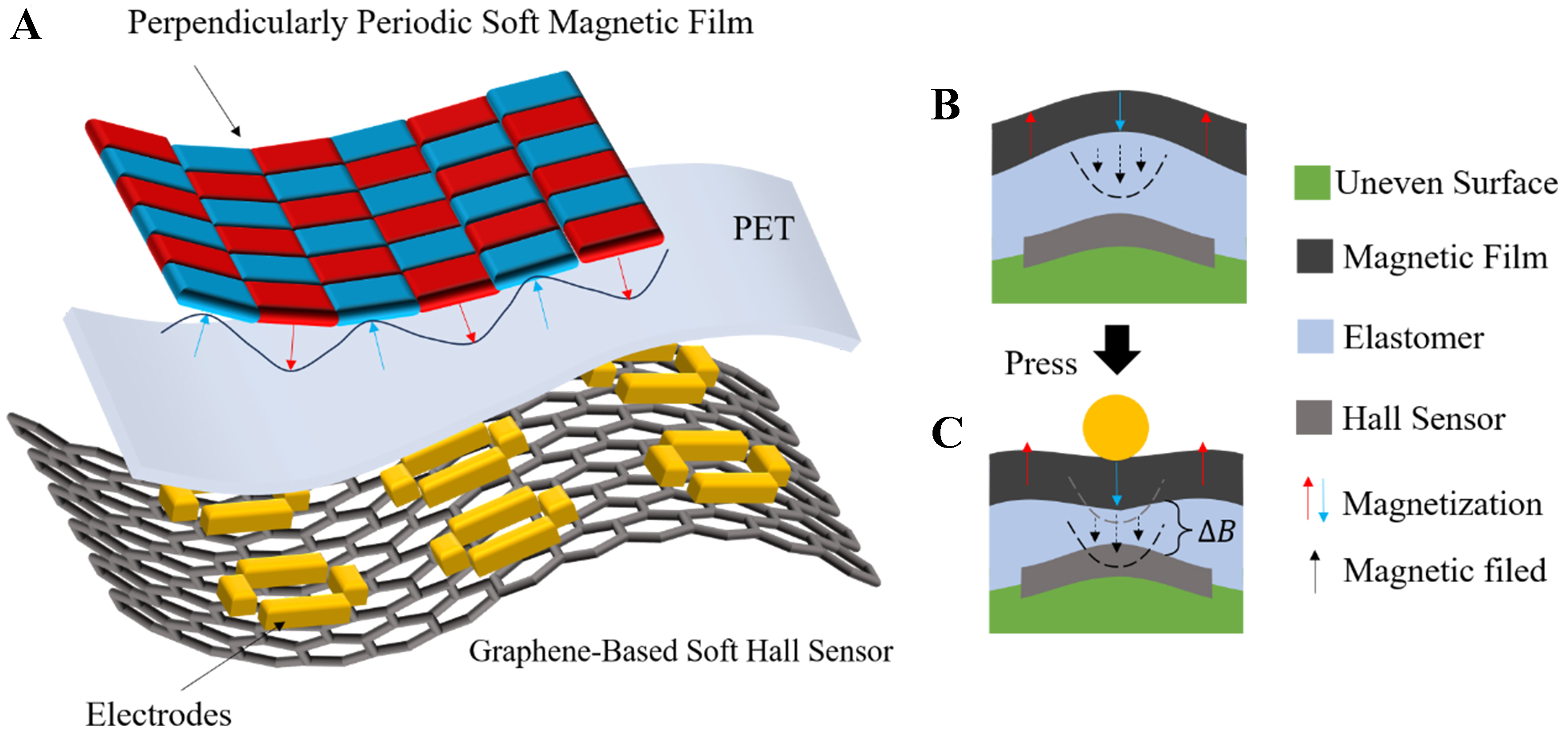
Figure 1. (A) Layer structure of the fully flexible super-resolution tactile sensor: periodically polarized flexible magnetic film, elastomer PET, 3 × 3 Hall sensor electrodes, and graphene substrate; (B) Initial state of the fully flexible Hall sensor; (C) Change in magnetic flux
where RH is the Hall coefficient, I is the magnitude of the current applied to the Hall sensor, and μ is the magnetoelastic coupling coefficient (defined in Supplementary Material Appendix A).
Graphene offers several advantages when employed in Hall sensors. Its exceptionally high carrier mobility significantly enhances sensitivity, reduces electronic noise, and enables the detection of magnetic fields at sub-microtesla levels. Its atomically thin structure (~0.335 nm) facilitates device miniaturization while maintaining superior performance. In addition, graphene’s excellent mechanical flexibility makes it well-suited for integration into flexible electronics and sensors. Its unique band structure contributes to improved temperature stability and linearity, enabling reliable operation across a wide temperature range. Furthermore, graphene’s compatibility with standard complementary metal-oxide-semiconductor (CMOS) processes and relatively simple fabrication requirements contribute to reduced manufacturing complexity and cost. Polyethylene terephthalate (PET), used as the substrate material, complements graphene with its transparency, mechanical flexibility, chemical durability, and low cost, making it highly suitable for applications in flexible and wearable electronics. The integration of graphene with PET substrates not only harnesses the individual strengths of both materials but also opens promising avenues for the advancement of high-performance, flexible sensor technologies.
Following the selection of suitable materials for the active region and substrate of the Hall sensors, the next critical step involves the structural design of the device. Although extensive research has been conducted on graphene-based Hall sensors[33-40], the majority of existing studies primarily focus on magnetic field detection along the z-axis. However, the tactile sensor proposed in this work necessitates high spatial resolution, which is defined by the size and density of individual sensing units within the sensor array. Spatial resolution directly influences the sensor’s ability to accurately capture and distinguish fine positional information, which is essential for precise tactile perception in flexible electronic applications.
To achieve high spatial resolution, the tactile sensor in this study adopts an array-based Hall sensor architecture. In principle, increasing the density of the array enhances spatial resolution, thereby enabling more accurate detection of contact force distribution and localization. However, excessively dense arrays introduce two primary challenges. First, a higher number of sensing units increases the complexity of metal interconnects and signal processing circuitry. Second, reducing the size of individual sensor elements to accommodate a denser layout can diminish the output signal strength, adversely affecting the overall sensitivity of the system. To balance spatial resolution, signal sensitivity, and the practicality of signal readout, a 3 × 3 Hall sensor array design is proposed in this work, as illustrated in Figure 2A.
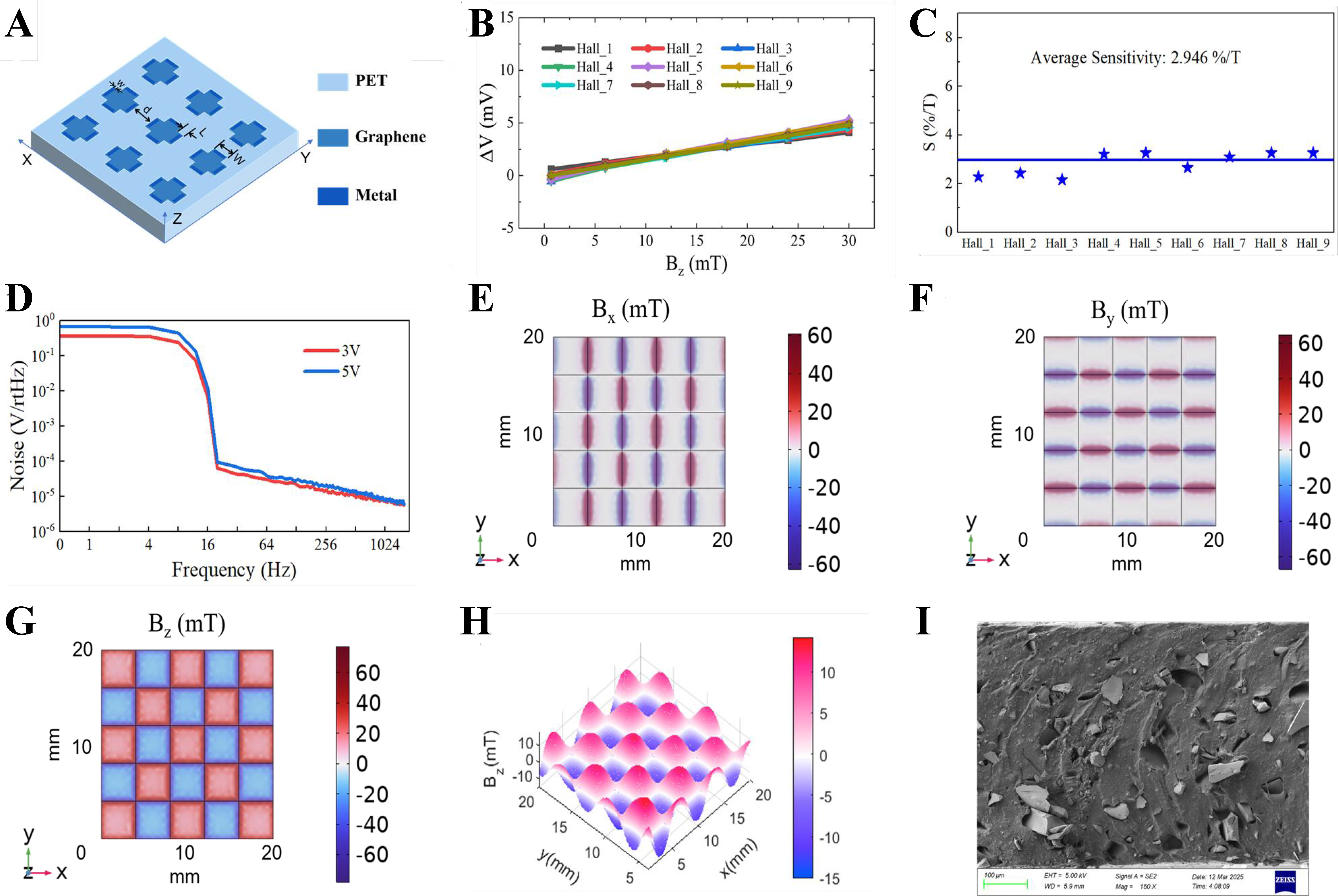
Figure 2. Design of Hall sensors and magnetic films. (A) Structure of flexible Hall sensors; (B) Output response of Hall sensors; (C) Sensitivity comparison of nine Hall sensors; (D) Noise testing of Hall sensors; (E-G) Simulation results of the x, y, z-axis magnetic field of the perpendicularly periodic magnetized film; (H) Test results of the z-axis magnetic field of a vertically periodic magnetized film; (I) SEM image of the magnetic film. SEM: Scanning electron microscope; PET: polyethylene terephthalate.
Previous studies[41] have demonstrated that the sensitivity of Hall sensors is maximized when the length-to-width (L/W) ratio of the sensing element is approximately 0.4. Accordingly, the flexible Hall sensors designed in this work maintain an L/W ratio of 0.4 to ensure optimal sensitivity. Ref[26] provides a detailed schematic of the human fingertip skin structure, including response profiles under localized pressure and simulations of skin responses to a spherical indenter at varying depths and lateral positions. These results indicate that indentations occurring 2-3 mm away from a mechanoreceptor (monitoring point) elicit negligible responses. The structural design of the proposed sensor mimics the layered architecture and localized sensitivity characteristics of human skin. When a contact force is applied directly at the sensing point - corresponding to the region of peak sensitivity - both the human skin (reflected in mechanoreceptor pulse frequency) and the magnetic tactile sensor (reflected in the out-of-plane magnetic field component Bz) exhibit maximal responses, which decay with increasing lateral displacement from the point of contact. Based on these insights, the 3 × 3 Hall sensor array was designed with the following dimensions and layout parameters: each sensor has a length L = 0.58 mm and width W = 1.45 mm (L/W = 0.4), with an inter-sensor spacing d = 2.4 mm and trace width w = 0.2 mm. These geometric features are annotated in Figure 2A.
Based on the above analysis, a flexible array-structured Hall sensor has been successfully designed. The proposed design optimizes both the array layout and the individual element dimensions, achieving a balanced trade-off between spatial resolution, signal strength, and signal processing complexity. By avoiding excessive array density, the structure preserves the effective signal output of each sensing unit while enhancing overall spatial resolution through a carefully considered array configuration. This design provides a robust foundation for the development of high-precision tactile sensing systems in flexible electronic applications.
The Hall sensor developed in this study adopts a 3 × 3 array configuration, consisting of nine individual sensing units. Each sensor was characterized to evaluate its magnetic field response within a flux density range of 0-30 mT, as illustrated in Figure 2B. The response curves of all nine sensors, as shown in Figure 2C, exhibit nearly identical behavior, demonstrating excellent uniformity across the array. The average sensitivity of the sensors was measured to be 2.946 %/T. The minimal variation in sensitivity among the sensing units indicates a high level of fabrication consistency, which is critical for ensuring reliable and uniform output in the context of tactile sensing applications.
As shown in Figure 2D, the voltage noise spectral density of the Hall sensor was measured under bias voltages of 3 and 5 V. Below the corner frequency of approximately 20 Hz, the noise is dominated by flicker noise, which increases with higher bias voltage. Above this frequency, the noise floor is governed by thermal noise, measured at 5.64 μV/√Hz. Based on these noise characteristics, the minimum detectable magnetic field strength of the sensor is calculated to be 38.29 μT/√Hz.
Compared to traditional vertically magnetized films, vertically periodically magnetized films achieve a regular, periodic distribution of magnetic domains along the z-axis while preserving vertical magnetization. This periodic domain arrangement forms closed magnetic circuits through alternating magnetic poles, effectively suppressing lateral magnetic field dispersion, reducing lateral magnetic flux leakage, and thereby enhancing the effective utilization of the z-axis magnetic field. When combined with the horizontally oriented Hall sensors designed to detect z-axis magnetic flux, this configuration offers significant advantages for magnetic tactile sensing applications.
The period size of the magnetization pattern also critically influences sensor performance. Under external pressure-induced deformation, smaller magnetic pole units produce more pronounced localized variations in the magnetic field, improving sensitivity to small forces. However, excessively small periods can induce strong magnetic domain coupling and increased demagnetizing field interference, which negatively impact signal stability and reduce the measurement range. To optimize these competing factors, this study employs a vertically periodically magnetized film with an 8 mm period, where each magnetic pole spans
Supplementary Figure 6 presents simulation results of the z-axis magnetic field at various heights above magnetic films with differing thicknesses. Four thicknesses were considered in this study: t1 = 0.25 mm, t2 = 0.5 mm, t3 = 0.75 mm, and t4 = 1 mm. The results indicate that the magnetic field strength at the film surface increases with thickness. Measurements were taken at four heights above the surface: h1 = 0.1 mm, h2 =
Magnetic films with varying thicknesses (0.25, 0.5, 0.75, and 1 mm) and different mass fractions of magnetic particles (40 wt.%, 50 wt.%, and 60 wt.%) were fabricated and characterized, as shown in Supplementary Figure 8. The magnetic flux density values presented correspond to measurements along the z-axis at the centers of individual magnetic poles. Error bars represent the variation in magnetic field strength across different pole centers within the same film, which was observed to be minimal. Results indicate that both increasing film thickness and higher magnetic particle mass fraction lead to an increase in the magnetic flux density at the pole centers. Notably, the magnetic film with a thickness of 1 mm and a 60 wt.% particle concentration exhibited magnetic flux densities of 10.65 and 11.74 mT at the centers of the north (N) and south (S) poles, respectively.
To achieve an optimal balance among sensitivity, flexibility, and dimensional constraints, the magnetic film with a thickness of 1 mm and a magnetic particle mass fraction of 60 wt.% was selected for subsequent experiments. The three-dimensional distribution of the z-axis magnetic field for this film is illustrated in Figure 2H, while Figure 2I presents a scanning electron microscope (SEM) image of the magnetic film.
A flexible magnetic tactile sensor was then assembled by integrating the vertically periodically magnetized film with the 3 × 3 arrayed Hall sensor, as shown in Figure 3A. Within the sensor array, nine discrete pressing positions labeled A through I correspond to the center points above each Hall sensor, denoted H1 through H9 [Figure 3B]. The tactile sensor’s output response was evaluated by applying pressure sequentially at each of these nine positions. Figure 3C displays the output response of Hall sensor H1 when pressure is applied at position A, with measurements repeated three times for reproducibility. Similar tests were conducted for the remaining eight positions. Figure 3D summarizes the sensitivity results, with an average sensitivity of 0.13 mV/N across all positions. To further validate the sensor’s performance, the linearity between applied pressure and output voltage was examined at the nine pressure points. Figure 3E shows the corresponding linear fitting coefficients, with an average coefficient of 0.97, indicating excellent linearity throughout the sensing area.
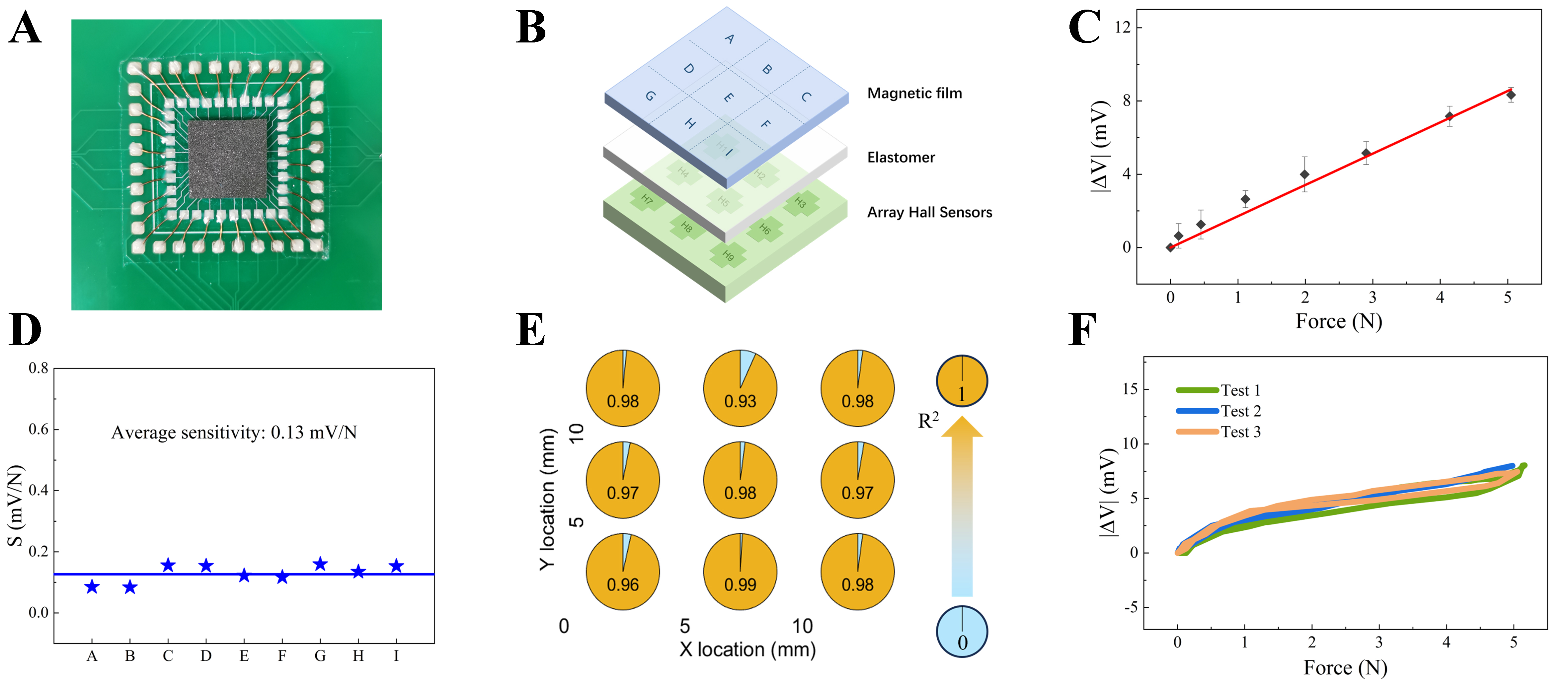
Figure 3. Tactile sensor design. (A) Packaging results for tactile sensors; (B) Schematic diagram of 3 × 3 press position; (C) Output response after applying force; (D) Comparison of sensitivity; (E) Linearity of the sensor; (F) Hysteresis testing of the sensor.
During force application, the tactile sensor exhibits hysteresis due to the elastic recovery properties of both the elastomer layer and the magnetic film. This results in a difference between the sensor output during loading and unloading cycles. To characterize this hysteresis behavior, cyclic loading was performed by applying a force from 0 to 5 N and subsequently releasing it back to 0 N. The experiment was repeated three times, as illustrated in Figure 3F. The maximum hysteresis observed in the sensor’s response was quantified as 11.4%.
High-resolution position sensing
With the Hall sensors arranged in a 3 × 3 array, a tactile sensor capable of 3 × 3 spatial resolution was initially implemented. Following the region division illustrated in Figure 3B, the center points of regions A through I were sequentially pressed, and the output voltages from all nine Hall sensors (H1-H9) were recorded for each pressing event. Figure 4 presents the output voltage responses corresponding to presses at regions A-I, along with sensor outputs under varying applied forces from 0 to 5 N. When region A is pressed, Hall sensor H1 - positioned directly beneath region A - exhibits the most pronounced voltage change. Similar spatial correlation patterns are observed for the other regions, with the sensor located immediately beneath the contact point showing the highest sensitivity. This behavior confirms that each Hall sensor’s most sensitive detection area corresponds spatially to the region directly above it. Leveraging this characteristic, the pressing position can be accurately determined by comparing the output voltages across the nine sensors, thereby enabling effective spatial position recognition within the 3 × 3 tactile sensor array.
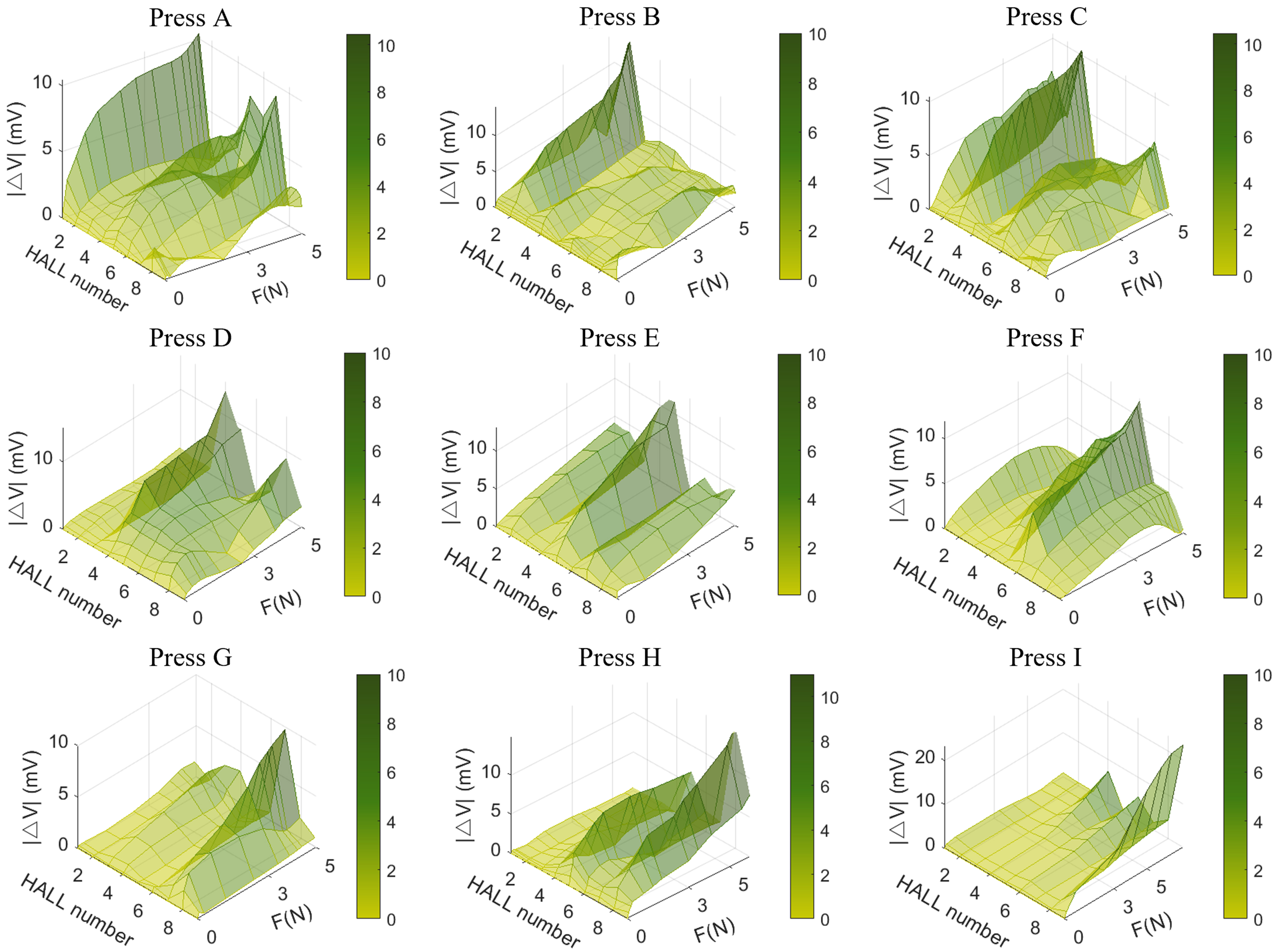
Figure 4. Output voltage comparison for presses at regions A-I.
Table 1 outlines the method employed to achieve spatial position recognition within the 3 × 3 tactile sensing unit. When a specific location is pressed, the DAQ system records the output voltage changes from all nine Hall sensors. These measurements are analyzed to identify the sensor exhibiting the maximum voltage variation, and the contact point is inferred to be directly above this sensor.
Judgment conditions for presses at regions A-I
| Condition | Result | Condition | Result | Condition | Result |
| |ΔVH1| > |ΔVHi,i=2-9| | A | |ΔVH2| > |ΔVHi,i=1,3-9| | B | |ΔVH3| > |ΔVHi,i=1,2,4-9| | C |
| |ΔVH4| > |ΔVHi,i=1-3,5-9| | D | |ΔVH5| > |ΔVHi,i=1-4,6-9| | E | |ΔVH6| > |ΔVHi,i=1-5,7-9| | F |
| |ΔVH7| > |ΔVHi,i=1-6,8,9| | G | |ΔVH8| > |ΔVHi,i=1-7,9| | H | |ΔVH9| > |ΔVHi,i=1-8| | I |
To validate this position recognition mechanism and assess its accuracy, repeated tests were conducted with each of the nine positions pressed ten times. Figure 5A compares the actual pressing positions with the predicted ones. The lowest recognition accuracy was observed at position B, located above Hall sensor H2. Despite this, the overall recognition accuracy remains high, demonstrating the system’s effective spatial position discrimination within the 3 × 3 tactile sensor array.
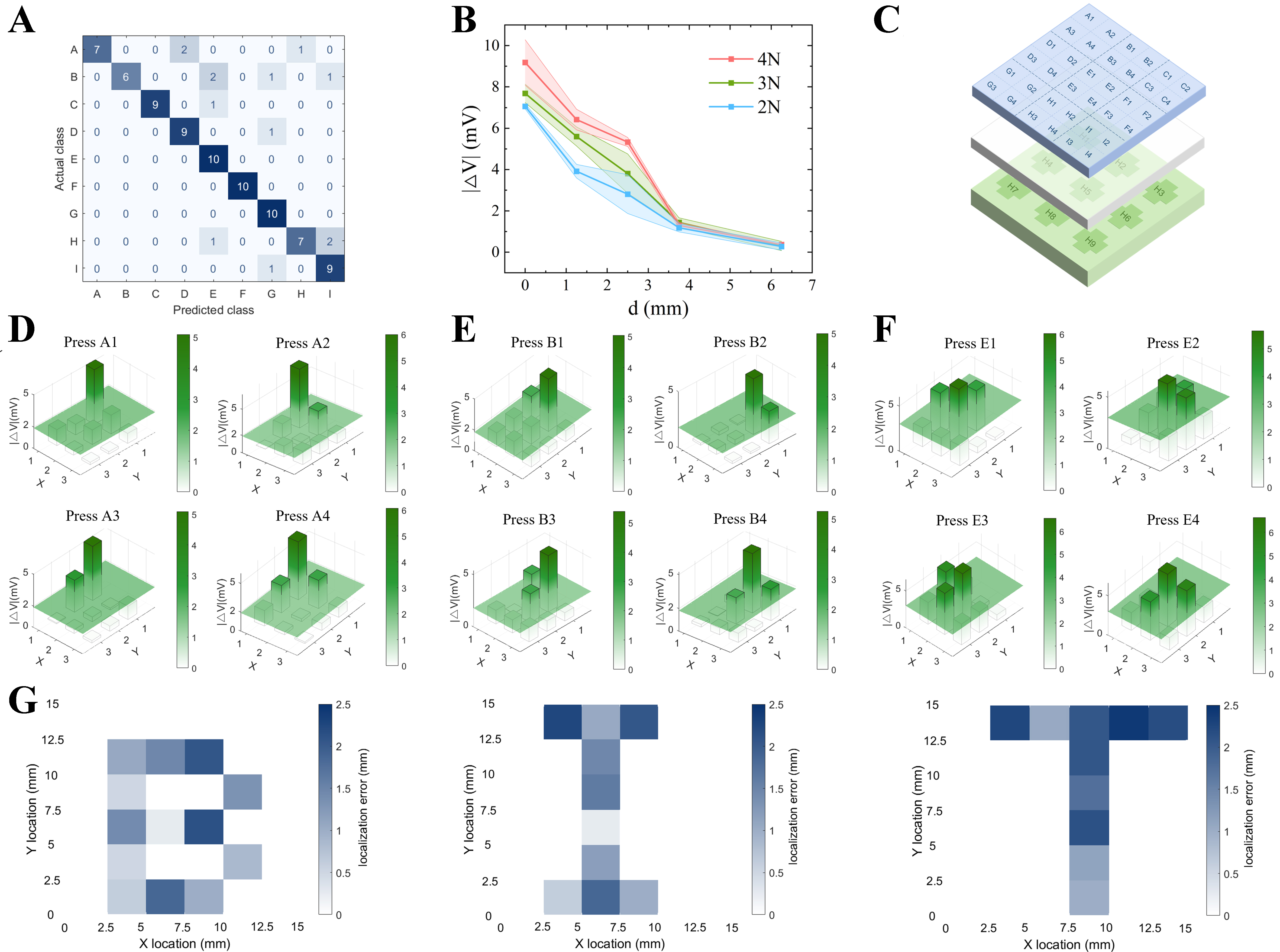
Figure 5. High-resolution position sensing. (A) 3 × 3 position recognition verification; (B) Relationship between pressing distance and output voltage; (C) 6 × 6 grid division; (D) Output comparison of presses at A1-A4; (E) Output comparison of presses at B1-B4; (F) Output comparison of presses at E1-E4; (G) 6 × 6 Position recognition verification.
The initial spatial resolution of 3 × 3 was primarily determined by the physical layout of the Hall sensor array. In the subsequent section, efforts are made to further enhance the sensor’s spatial resolution. A critical preliminary step involves identifying the maximum detectable pressing distance for each individual Hall sensor. As illustrated in Figure 5B, the output voltage change of a Hall sensor decreases with increasing horizontal distance d from the pressing point under applied forces of 2, 3, and 4 N. The sensor response becomes negligible when the distance reaches approximately 6.25 mm. The error bands shown in the figure represent the variability observed over multiple measurement trials.
Building on the previous findings and considering that the spacing between adjacent Hall sensors in the initial design was 5 mm, the original 3 × 3 sensing area was further subdivided into a 6 × 6 grid. Specifically, each original region was divided into four smaller subregions (2 × 2), as illustrated in Figure 5C. For instance, region A was subdivided into A1, A2, A3, and A4, with the same subdivision applied to the other regions. According to the data shown in Figure 5D, Hall sensor H1 responds to pressure applied at points A1-A4 and at B1, B3, D1, and D2, with the strongest responses corresponding to the subregions within A1-A4. Similar response distributions were observed for the other Hall sensors. These results demonstrate that the spatial resolution of the tactile sensor can be effectively enhanced beyond the original 3 × 3 configuration.
In this study, the pressing position is determined by analyzing and comparing the output variations across all nine Hall sensors, representing an advancement over the previous 3 × 3 spatial resolution approach, which relied solely on identifying the sensor with the largest output change. The current method not only identifies the sensor exhibiting the maximum response but also examines the output variations of neighboring sensors to improve positional accuracy.
As illustrated in Figure 5D, when pressing points A1 through A4 with a force of 3 N, Hall sensor H1 consistently shows the largest output variation. Among the remaining sensors, H3 and H5-H9 exhibit negligible responses, while sensors H2 and H4 demonstrate significant variation patterns that differ depending on the exact pressing location. Specifically, for press A1, output variations in H2 and H4 are minimal; at A2, H2 shows a pronounced response while H4 remains nearly unchanged; at A3, H4 shows a strong variation whereas H2 remains stable; and at A4, both H2 and H4 exhibit relatively large responses.
Based on these observations, an empirical threshold was established to differentiate valid sensor signals from noise-induced fluctuations. Output variations exceeding this threshold are considered valid and contribute to position recognition, while those below are treated as invalid. The threshold plane illustrated in Figure 5D represents this empirically derived criterion.
From the preceding analysis, it is evident that the output signal patterns corresponding to pressing positions A1-A4 are distinct, enabling reliable identification of the pressing location based on these unique signatures. The specific criteria for this classification are summarized in Table 2. Furthermore, the response patterns for pressing positions C1-C4, G1-G4, and I1-I4 exhibit symmetry with those of A1-A4. Detailed supporting data, including response curves and quantitative comparisons, are provided in Supplementary Figures 9-11 and Supplementary Tables 1-3, which confirm the consistency of these symmetric patterns across the sensor array.
Judgmental conditions for presses at regions A1-A4
| Condition | Result |
| |ΔVH1| > |ΔVHi,i=2-9|, |ΔVHi,i=2-9| < | A1 |
| |ΔVH1| > |ΔVHi,i=2-9|, |ΔVH2| > | A2 |
| |ΔVH1| > |ΔVHi,i=2-9|, |ΔVH4| > | A3 |
| |ΔVH1| > |ΔVHi,i=2-9|, |ΔVH2| > | A4 |
Figure 5E presents the output comparisons of the nine Hall sensors when pressing positions B1-B4 with a
Judgmental conditions for presses at regions B1-B4
| Condition | Result |
| |ΔVH2| > |ΔVHi,i=1,3-9|, |ΔVH1| > | B1 |
| |ΔVH2| > |ΔVHi,i=1,3-9|, |ΔVH3| > | B2 |
| |ΔVH2| > |ΔVHi,i=1,3-9|, |ΔVH1| > | B3 |
| |ΔVH2| > |ΔVHi,i=1,3-9|, |ΔVH3| > | B4 |
Similarly, Figure 5F compares sensor outputs when pressing positions E1-E4 under a 3 N load, with the threshold plane again indicated in green. Sensor H5 consistently exhibits the largest output variation. Specific sensor responses include: H2 responding to E1 and E2; H8 to E3 and E4; H4 to E1 and E3; and H6 to E2 and E4. These unique output patterns for E1-E4 enable precise position identification, with detailed criteria provided in Table 4.
Judgmental conditions for presses at regions E1-E4
| Condition | Result |
| |ΔVH5| > |ΔVHi,i=1-4,6-9|, |ΔVH2| > | E1 |
| |ΔVH5| > |ΔVHi,i=1-4,6-9|, |ΔVH2| > | E2 |
| |ΔVH5| > |ΔVHi,i=1-4,6-9|, |ΔVH4| > | E3 |
| |ΔVH5| > |ΔVHi,i=1-4,6-9|, |ΔVH6| > | E4 |
Collectively, these analyses confirm that each subregion within the 6 × 6 sensing grid produces a distinct output pattern when pressed, allowing for accurate spatial position recognition across the entire sensing area.
To further validate the position recognition method, sequential presses were applied on the sensor surface to trace the letters “B”, “I”, and “T”. Each subregion forming these letters was pressed 10 times, and the recognition accuracy and positioning errors were recorded. As shown in Figure 5G, the maximum positioning error was 2.41 mm, with an average of 1.37 mm, demonstrating the system’s high spatial accuracy and reliability.
CONCLUSIONS
This paper presents the design and fabrication of a magnetic tactile sensor based on a flexible array-type Hall sensor integrated with a vertically periodically magnetized film. Graphene was selected as the active sensing material for the Hall sensor due to its superior flexibility and high carrier mobility, while PET was employed as the flexible substrate to ensure overall device compliance. The array-type Hall sensor was structurally engineered with reference to the deformation characteristics of human skin, with optimized parameters to guarantee reliable response under applied pressure. Comparative analysis between conventional vertically magnetized films and vertically periodic magnetized films demonstrated that the latter offers enhanced local magnetic field concentration and effective suppression of lateral magnetic interference, thereby improving compatibility with z-axis flexible Hall sensor arrays. By optimizing the magnetization period and individual magnetic pole dimensions, surface magnetic flux densities of 10.65 mT (N-pole) and 11.74 mT (S-pole) were achieved, providing a robust magnetic field for high-resolution spatial sensing. The fabricated fully flexible tactile sensor exhibited excellent performance, characterized by an average sensitivity of 0.13 mV/N, a linearity coefficient of 0.97, and a hysteresis rate of 11.4%. Spatial position recognition was realized through feature extraction and classification of output responses from nine Hall sensors within a 3 × 3 array. Further refinement of the pressure array and signal discrimination enabled spatial recognition in an expanded 6 × 6 sensing unit array, demonstrating the sensor’s potential for high-precision tactile applications.
DECLARATIONS
Authors’ contributions
Performed manuscript writing and figure preparation: Li, X.; Gao, W.
Performed data analysis and interpretation: Wang, B.; Jiao, W.; Su, H.
Provided experimental conditions for supplementary data: Zhou, W.
Supervised the overall structure, provided critical feedback, and finalized the manuscript: Wang, X.; Shen, Y.; Xie, H.
Availability of data and materials
All data are available in the main text or the Supplementary Materials. Further information can be obtained from the corresponding authors upon reasonable request.
Financial support and sponsorship
This research was financially supported by the National Natural Science Foundation of China (62304023), Beijing Natural Science Foundation under Grant (4252062), and the National Key R&D Program of China (2023YFB3507300).
Conflicts of interest
All authors declared that there are no conflicts of interest.
Ethical approval and consent to participate
Not applicable.
Consent for publication
Not applicable.
Copyright
© The Author(s) 2025.
Supplementary Materials
REFERENCES
1. Chang, T. H.; Tian, Y.; Li, C.; et al. Stretchable graphene pressure sensors with Shar-Pei-like hierarchical wrinkles for collision-aware surgical robotics. ACS. Appl. Mater. Interfaces. 2019, 11, 10226-36.
2. Wang, Y.; Chen, J.; Mei, D. Recognition of surface texture with wearable tactile sensor array: a pilot study. Sens. Actuators. A. Phys. 2020, 307, 111972.
3. Wang, Y.; Chao, M.; Wan, P.; Zhang, L. A wearable breathable pressure sensor from metal-organic framework derived nanocomposites for highly sensitive broad-range healthcare monitoring. Nano. Energy. 2020, 70, 104560.
4. Mao, R.; Yao, W.; Qadir, A.; et al. 3-D graphene aerogel sphere-based flexible sensors for healthcare applications. Sens. Actuators. A. Phys. 2020, 312, 112144.
5. Guo, Y.; Guo, Z.; Zhong, M.; Wan, P.; Zhang, W.; Zhang, L. A flexible wearable pressure sensor with bioinspired microcrack and interlocking for full-range human-machine interfacing. Small 2018, 14, e1803018.
6. Kumar, A. Methods and materials for smart manufacturing: additive manufacturing, Internet of Things, flexible sensors and soft robotics. Manuf. Lett. 2018, 15, 122-5.
7. Lin, X.; Gao, S.; Fei, T.; Liu, S.; Zhao, H.; Zhang, T. Study on a paper-based piezoresistive sensor applied to monitoring human physiological signals. Sens. Actuators. A. Phys. 2019, 292, 66-70.
8. Jiang, Y.; Liang, F.; Li, H. Y.; et al. A flexible and ultra-highly sensitive tactile sensor through a parallel circuit by a magnetic aligned conductive composite. ACS. Nano. 2022, 16, 746-54.
9. Hellebrekers, T.; Kroemer, O.; Majidi, C. Soft magnetic skin for continuous deformation sensing. Adv. Intell. Syst. 2019, 1, 1900025.
10. Ge, J.; Wang, X.; Drack, M.; et al. A bimodal soft electronic skin for tactile and touchless interaction in real time. Nat. Commun. 2019, 10, 4405.
11. Le Signor, T.; Dupre, N.; Close, G. F. A gradiometric magnetic force sensor immune to stray magnetic fields for robotic hands and grippers. IEEE. Robot. Autom. Lett. 2022, 7, 3070-6.
12. Xu, J.; Tat, T.; Zhao, X.; et al. A programmable magnetoelastic sensor array for self-powered human–machine interface. Appl. Phys. Rev. 2022, 9, 031404.
13. Shu, Q.; Xu, Z.; Liu, S.; et al. Magnetic flexible sensor with tension and bending discriminating detection. Chem. Eng. J. 2022, 433, 134424.
14. Xie, S.; Zhang, Y.; Jin, M.; Li, C.; Meng, Q. High sensitivity and wide range soft magnetic tactile sensor based on electromagnetic induction. IEEE. Sens. J. 2021, 21, 2757-66.
15. Becker, C.; Bao, B.; Karnaushenko, D. D.; et al. A new dimension for magnetosensitive e-skins: active matrix integrated micro-origami sensor arrays. Nat. Commun. 2022, 13, 2121.
16. Zhang, X.; Hu, H.; Tang, D.; Zhang, C.; Fu, J.; Zhao, P. Magnetic flexible tactile sensor via direct ink writing. Sens. Actuators. A. Phys. 2021, 327, 112753.
17. Guan, X.; Wang, Z.; Zhao, W.; et al. Flexible piezoresistive sensors with wide-range pressure measurements based on a graded nest-like architecture. ACS. Appl. Mater. Interfaces. 2020, 12, 26137-44.
18. Wei, Y.; Shi, X.; Yao, Z.; et al. Fully paper-integrated hydrophobic and air permeable piezoresistive sensors for high-humidity and underwater wearable motion monitoring. npj. Flex. Electron. 2023, 7, 244.
19. Zhao, T.; Yuan, L.; Li, T.; Chen, L.; Li, X.; Zhang, J. Pollen-shaped hierarchical structure for pressure sensors with high sensitivity in an ultrabroad linear response range. ACS. Appl. Mater. Interfaces. 2020, 12, 55362-71.
20. Lv, C.; Tian, C.; Jiang, J.; et al. Ultrasensitive linear capacitive pressure sensor with wrinkled microstructures for tactile perception. Adv. Sci. 2023, 10, e2206807.
21. Farman, M.; Surendra,
22. Bai, N.; Wang, L.; Xue, Y.; et al. Graded interlocks for iontronic pressure sensors with high sensitivity and high linearity over a broad range. ACS. Nano. 2022, 16, 4338-47.
23. Dahiya, S. R.; Valle, M. Tactile sensing for robotic applications. In: Gerardo J, Lanceros-Mendez S, editors. Sensors: focus on tactile force and stress sensors. InTech; 2008.
24. Zapata-Impata, B. S.; Gil, P.; Torres, F. Tactile-driven grasp stability and slip prediction. Robotics 2019, 8, 85.
25. Wang, C.; Dong, L.; Peng, D.; Pan, C. Tactile sensors for advanced intelligent systems. Adv. Intell. Syst. 2019, 1, 1900090.
26. Yan, Y.; Hu, Z.; Yang, Z.; et al. Soft magnetic skin for super-resolution tactile sensing with force self-decoupling. Sci. Robot. 2021, 6, eabc8801.
27. Yan, Y.; Shen, Y.; Song, C.; Pan, J. Tactile super-resolution model for soft magnetic skin. IEEE. Robot. Autom. Lett. 2022, 7, 2589-96.
28. Hu, H.; Zhang, C.; Pan, C.; et al. Wireless flexible magnetic tactile sensor with super-resolution in large-areas. ACS. Nano. 2022, 16, 19271-80.
29. Hu, H.; Zhang, C.; Lai, X.; et al. Large-area magnetic skin for multi-point and multi-scale tactile sensing with super-resolution. npj. Flex. Electron. 2024, 8, 325.
30. Wu, B.; Liu, Q.; Zhang, Q. Tactile pattern super resolution with taxel-based sensors. In 2022 IEEE/RSJ International Conference on Intelligent Robots and Systems (IROS), Kyoto, Japan. October 23-27, 2022. IEEE; 2022. pp 3644-50.
31. Xia, Z.; Fang, B.; Sun, F.; et al. Contact shape and pose recognition: utilizing a multipole magnetic tactile sensor with a metalearning model. IEEE. Robot. Automat. Mag. 2022, 29, 127-37.
32. Man, J.; Chen, G.; Chen, J. Recent progress of biomimetic tactile sensing technology based on magnetic sensors. Biosensors 2022, 12, 1054.
33. Huang, L.; Zhang, Z.; Chen, B.; Peng, L. M. Flexible graphene Hall sensors with high sensitivity. In 2015 IEEE International Electron Devices Meeting (IEDM), Washington, USA. December 07-09, 2015. IEEE; 2015. pp 33.5.1-4.
34. Kaidarova, B. A.; Liu, W.; Swanepoel, L.; et al. Flexible Hall sensor made of laser-scribed graphene. npj. Flex. Electron. 2021, 5, 100.
35. Xu, H.; Huang, L.; Zhang, Z.; Chen, B.; Zhong, H.; Peng, L. Flicker noise and magnetic resolution of graphene hall sensors at low frequency. Appl. Phys. Lett. 2013, 103, 112405.
36. Li, P.; Collomb, D.; Lim, Z. J.; et al. High resolution magnetic microscopy based on semi-encapsulated graphene Hall sensors. Appl. Phys. Lett. 2022, 121, 043502.
37. Shah, N.; Iyer, V.; Zhang, Z.; et al. Highly stable integration of graphene Hall sensors on a microfluidic platform for magnetic sensing in whole blood. Microsyst. Nanoeng. 2023, 9, 71.
38. Schaefer, B. T.; Wang, L.; Jarjour, A.; et al. Magnetic field detection limits for ultraclean graphene Hall sensors. Nat. Commun. 2020, 11, 4163.
39. Collomb, D.; Li, P.; Bending, S. J. Nanoscale graphene Hall sensors for high-resolution ambient magnetic imaging. Sci. Rep. 2019, 9, 14424.
40. Izci, D.; Dale, C.; Keegan, N.; Hedley, J. The construction of a graphene Hall effect magnetometer. IEEE. Sens. J. 2018, 18, 9534-41.
Cite This Article
How to Cite
Download Citation
Export Citation File:
Type of Import
Tips on Downloading Citation
Citation Manager File Format
Type of Import
Direct Import: When the Direct Import option is selected (the default state), a dialogue box will give you the option to Save or Open the downloaded citation data. Choosing Open will either launch your citation manager or give you a choice of applications with which to use the metadata. The Save option saves the file locally for later use.
Indirect Import: When the Indirect Import option is selected, the metadata is displayed and may be copied and pasted as needed.
About This Article
Special Topic
Copyright

Data & Comments
Data
0


Comments
Comments must be written in English. Spam, offensive content, impersonation, and private information will not be permitted. If any comment is reported and identified as inappropriate content by OAE staff, the comment will be removed without notice. If you have any queries or need any help, please contact us at [email protected].