


Neutron imaging quantifying hydrogen diffusion and distribution in metallic materials - a review
 0
0 Abstract
Neutron imaging (NI) has emerged as a pivotal non-destructive characterization technique, leveraging its exceptional penetration through heavy metals and high sensitivity to light elements such as hydrogen and lithium. These unique properties render NI indispensable for the quantitative assessment of hydrogen in metallic materials, where hydrogen accumulation can significantly degrade mechanical performance. In this context, in-situ experimental setups capable of precise control over temperature, gas environment, and mechanical stress enable real-time monitoring of hydrogen absorption, diffusion, and spatial distribution. Recent advancements in NI have achieved hydrogen detection with concentrations as low as 5-10 wppm and spatial resolutions on the order of
Keywords
INTRODUCTION
Neutron imaging has emerged as a non-destructive evaluation method, employing the distinctive interaction between neutrons and atomic nuclei to investigate material properties[1,2]. Recent advancements in neutron source design, detector technology, and computational algorithms have facilitated advanced experimental capabilities, including high spatial resolution attenuation imaging[3], Bragg-edge imaging[4,5], and grating imaging[6]. Attenuation imaging relies on the scattering and absorption of neutrons by materials. Variations in the neutron counts transmitted through different materials generate image contrast, reflecting differences in neutron attenuation coefficients. Bragg-edge imaging utilizes wavelength dependent diffraction between neutron beam and crystalline lattices. Intensity contrast arises at specific wavelengths, enabling phase identification. Additionally, lattice distortion induced by stresses alters Bragg-edge profiles, allowing for quantitative stress mapping in specific phases[7]. Grating imaging, a recently developed technique, employs periodic grating structures to achieve sub-micrometer resolution[6]. Through the design of user-oriented experimental setups, in situ monitoring under extreme conditions (e.g., high temperature, mechanical stress), as well as operando studies of dynamic processes (e.g., hydrogen diffusion, phase transformation), have become achievable[8-10].
In comparison with X-rays, which exhibit strong penetration through light elements but limited efficacy in dense metallic systems, neutrons provide exceptional penetration depth up to several centimeters in metals while maintaining sensitivity to light elements such as hydrogen, boron and lithium[11,12]. This complementary capability makes neutron imaging an indispensable tool for analyzing hydrogen in metallic materials, where conventional techniques cannot resolve hydrogen distribution without destructive characterization. The unique advantage of neutron imaging lies in its ability to generate hydrogen specific contrast via neutron interaction with hydrogen nuclei, enabling non-destructive visualization of hydrogen distributions within bulk metallic specimens. This is particularly crucial for hydrogen storage alloys, and high strength steels[13,14].
Hydrogen is a common element with wide importance in many areas, such as nuclear energy and storing hydrogen[8]. However, when it comes into contact with other materials, it can cause serious damage, known as Hydrogen-Induced Damage (HID). The destructive effect of hydrogen on materials is complex and gradual, affecting atomic-level interaction, microstructural changes, and overall material failure. These effects show up as hydrogen embrittlement (HE), hydrogen attack and HID, each of which contributes to the degradation of material properties and performance under hydrogen exposure. HE is the most damaging form of HID, causing brittle fractures in metals such as high-strength steel and titanium/zirconium alloys, even under stresses much lower than the material’s yield strength. In this process, hydrogen atoms gather at the tips of cracks under stress, weakening the bonds between atoms and leading to early fracture[5]. In titanium and zirconium alloys, hydrogen reacts with the material to form brittle hydrides (e.g., ZrH1.5), which can cause delayed cracking known as delayed hydride cracking (DHC). DHC failure in nuclear fuel cladding under high temperature, water-cooled conditions is a major safety concern. Hydrogen attack is commonly observed in steels exposed to high-temperature and high-pressure environments such as in petrochemical reactors[10]. This type of damage is often hard to detect during service and can lead to catastrophic failures. Additionally, hydrogen-assisted cracking occurs during processes such as welding, electroplating, or in corrosive environments, where hydrogen enters materials through cracks or corrosive media. The sudden and hidden nature of HID presents serious risks to industries such as nuclear power and hydrogen storage, highlighting the importance of analyzing hydrogen distribution. This paper focuses on attenuation imaging, which is a type of neutron imaging, and reviews its applications in hydrogen containing metallic systems in recent years, while also offering perspective on future developments.
PRINCIPLES OF NEUTRON ATTENUATION IMAGING
Neutrons have a unique property: they are electrically neutral. This allows them to form beams that carry no charge, making them highly useful for neutron imaging[15]. Unlike X-rays, which interact with the electrons in atoms, neutrons only interact with atomic nuclei due to their neutral charge. While both X-ray and neutron imaging share some basic principles, such as the variation in mass attenuation coefficients across different materials, the interaction mechanisms of neutrons and X-rays with matter are different, leading to distinct mass attenuation coefficients. X-ray attenuation is directly related to the number of electrons outside the atomic nucleus, increasing as atomic number rises. In contrast, neutrons attenuation is influenced by more complex processes and their attenuation coefficients are not dependent on the atomic number. The distribution of neutron attenuation coefficients is independent of atomic number and can be utilized to distinguish isotopes (for instance, 1H and 2H)[16].
Research indicates that at a temperature of 473 K, the total neutron cross section of light water and heavy water, assessed using thermal neutrons at 25.3 meV, exhibits a considerable difference, nearly two orders of magnitude apart[17]. The main reason for this discrepancy is that the atomic nuclei of the two substances have different masses, which influences how momentum and energy are transferred during elastic scattering. Inelastic scattering, on the other hand, is affected by changes in the energy levels of the nuclei. Additionally, in terms of absorption cross section, deuterium exhibits a lower neutron capture probability. This enables neutron techniques to distinctly differentiate between two materials, despite their identical electron configurations. Neutron-nucleus interactions can be divided into two fundamental categories that collectively determine the neutron cross section σ: (i) absorption cross section (σa), characterized by neutron capture via nuclear reactions; and (ii) scattering cross section (σs), which is governed by the exchange of momentum with atomic nuclei. The scattering cross section is further divided into coherent elastic scattering (similar to Rayleigh scattering of X-rays), incoherent elastic scattering (Thomson scattering), and inelastic scattering (Compton scattering). In liquid system with short-range order and long-range disorder, scattering dominates and behaves depending on energy. At low energy (E < 1 meV), elastic scattering occurs with minimal transfer; at intermediate energies (1 meV < E < 0.1 eV), quasi-elastic scattering prevails, especially in liquids containing light elements; and at higher energies (E > 0.1 eV), inelastic scattering, which causes molecular vibrations, becomes important. Additionally, light elements have a greater impact on these interactions due to their large scattering cross section[18]. In multiphonon (solid) state, the inelastic scattering component of neutron interactions is predominantly modulated by the phonon density of states (DOS). The scattering cross section increases with the DOS, as seen in metals and their hydrides. Also, higher temperatures lead to more thermally excited phonons, increasing multiphonon scattering cross section[19]. X-rays interact with matter in several ways, including the photoelectric effect, Rayleigh scattering, Compton scattering, and electron-positron pair formation, all of which are caused by interactions with electrons in atoms. Neutrons, on the other hand, interact directly with atomic nuclei. Figure 1A and B shows how X-rays and neutrons interact with matter in different ways[2]. Table 1 demonstrates that hydrogen has a much greater neutron cross-section than other materials. Thus, it is theoretically demonstrated that neutron attenuation imaging has an extremely strong characterization capability for hydrogen in metals[20]. The comparison between the reaction ability of X-rays with matter and the cross section of the interaction between neutron beams and matter is depicted in Figure 1C.
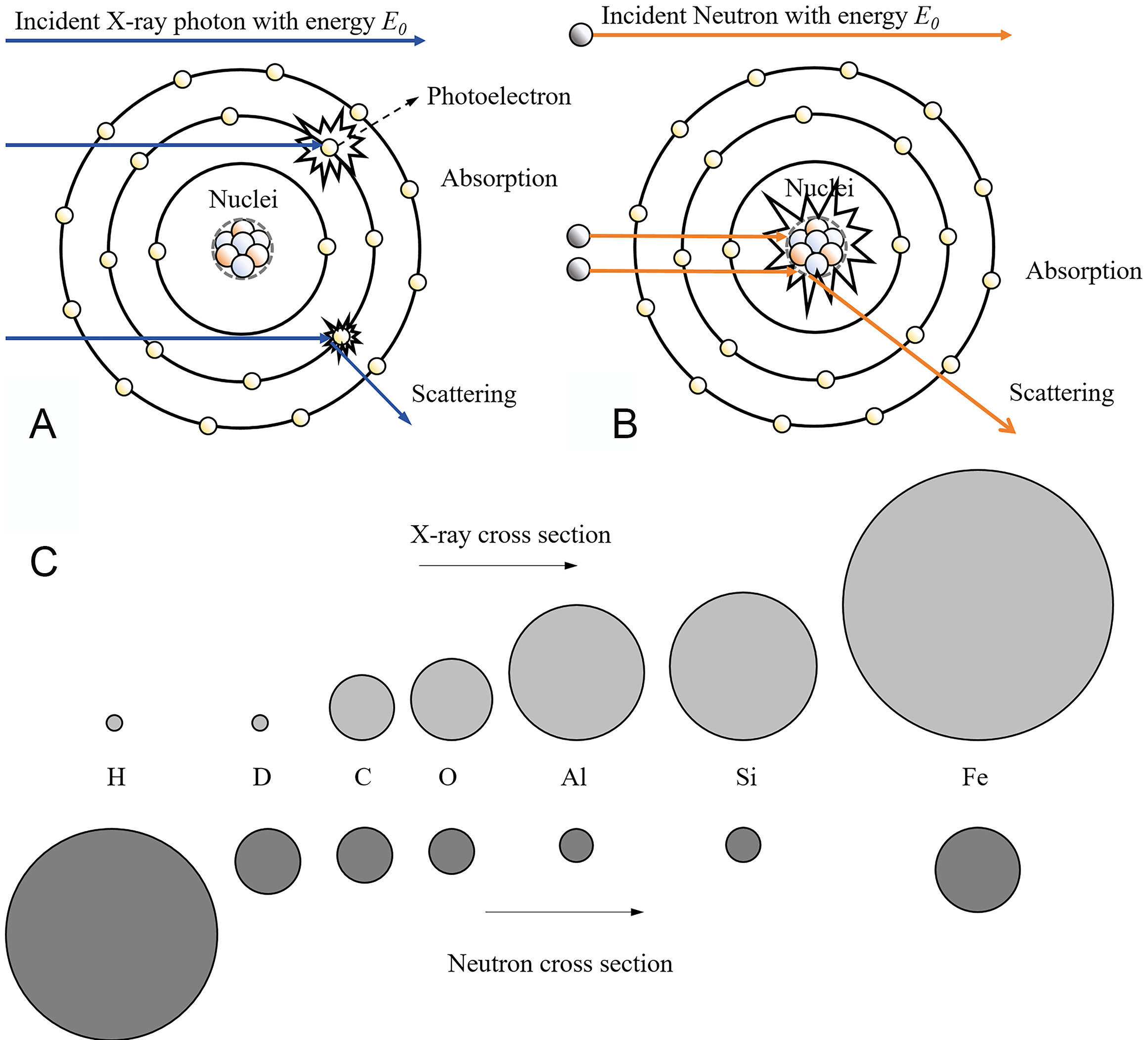
Figure 1. Comparison of the interaction of X-rays and neutron beams: (A) interaction with atom, (B) the relative cross sections of common elements, (C) cross sections of common elements[2].
Total bound scattering cross section (σs) and absorption cross section for thermal neutron (σa) in barns with a neutron energy 25.3 meV[20]
| H | D | Li | C | ||||
| σs | σa | σs | σa | σs | σa | σs | σa |
| 82.02 | 0.332 | 7.64 | 0.000519 | 1.37 | 70.5 | 5.551 | 0.0035 |
| O | Ti | Fe | Zr | ||||
| σs | σa | σs | σa | σs | σa | σs | σa |
| 4.232 | 0.00019 | 4.35 | 6.09 | 11.62 | 2.56 | 6.46 | 0.185 |
There are two major ways in which neutrons interact with atomic nuclei: absorption and scattering. The total neutron cross section is the sum of these two interactions. When a neutron is absorbed by a nucleus, it usually emits gamma rays, which account for a definite portion of the total cross section. Scattering, on the other hand, occurs when a neutron collides with a nucleus and changes its energy and direction without being absorbed. The spin state of hydrogen molecules has an effect on scattering[18]. Neutron energy also affects scattering; as neutron energy increases, i.e., from cold neutrons (μeV-meV) to epithermal neutrons (eV-keV), the scattering cross section changes from the bound-nucleus value to the free-nucleus value[19].
Neutron beams irradiate objects and are attenuated through absorption and scattering by the objects. The attenuation of the incident neutron beam depends on the thickness and elemental composition of the sample. Neutron attenuation imaging is based on the Beer-Lambert law, as given below[21]:
where I indicates the intensity of transmitted intensity, I0 represents the incident intensity, ∑t stands for the neutron attenuating cross section, and x denotes the thickness of the target material.
Neutron imaging has long been used to determine hydrogen content in metal samples by analyzing the attenuation of a neutron beam as it passes through the specimen. The extent of attenuation reflects the overall hydrogen concentration within the material. The attenuation coefficient is a critical parameter in neutron imaging studies. The mean attenuation coefficient of hydrogen is typically higher than that of metallic materials, primarily due to the incoherent scattering of hydrogen[22]. The incoherent scattering cross section of neutrons with hydrogen nuclei is very large; therefore, the presence of hydrogen significantly increases the attenuation of materials to neutrons. Differences in attenuation coefficients enable the effective detection of hydrides by measuring neutron beam attenuation as it passes through a sample. In studies quantifying hydrogen concentration in metallic materials, the neutron transmission relationship defines
where Idc indicates dark current, the detector signal in the absence of neutrons, Iob denotes the open-beam intensity without the sample, ∑total represents the total macroscopic neutron cross section of the material, and s signifies the neutron path length through the sample. In the confined state, strong external potential forces restrict the movement of hydrogen nuclei. Within the lattice of metal hydrides, hydrogen nuclei oscillate around their equilibrium positions. In contrast, in water molecules, hydrogen nuclei form strong covalent bonds with oxygen atoms and weaker hydrogen bonds with neighboring molecules, which limit their mobility. The bound-state scattering cross-section (σbound) exhibits a strong environmental dependence. The σbound of hydrogen in zirconium hydride (ZrHX) varies with the peak position of the lattice phonon DOS and is lower than the scattering cross-section in the free state. In the free state, hydrogen nuclei are completely unbound from external constraints and exist as freely mobile atoms. At this stage, the interaction between neutrons and hydrogen nuclei is dominated solely by nuclear forces, with the influence of confining potentials becoming negligible. The free-state scattering cross-section (σfree) thus exhibits a significantly simplified energy dependence. In general, the neutron cross section shows an inverse dependence on energy, with distinct behaviors observed across three energy regimes: (1) In the lower energy range (E < 1 eV), the absorption cross section increases as the neutron velocity decreases, since the probability of absorption is inversely proportional to the neutron velocity (v). The scattering cross section in this regime is predominantly governed by coherent scattering, akin to Rayleigh scattering of photons, where the scattered waves maintain phase correlation. This phenomenon leads to diffraction effects due to the matching of neutron wavelengths with atomic spacing in crystalline structures; (2) In the medium energy range (1 eV < E < 0.1 MeV), the probability of neutron capture is significantly enhanced when the neutron energy matches the energy of the nuclear excited state, resulting in the formation of highly unstable compound nucleus. In resonant scattering, neutrons are temporarily captured by the nucleus and subsequently re-emitted (inelastic scattering), causing the scattering cross section to vary sharply with energy; (3) At high energies (E > 0.1 MeV), the interaction time between the neutrons and atomic nuclei is reduced, which leads to lower probability of interaction, thereby decreasing the neutron cross section[17]. The empirically determined macroscopic cross-section in Equation (2) facilitates quantitative hydrogen characterization in materials. Then, for the hydrogen-containing materials[24]:
where ∑metal denotes the cross section of metal, σH represents the microscopic cross section of hydrogen, and NH stands for the atomic number density of hydrogen. To enhance statistical efficiency and simplify the neutron transmission and hydrogen concentration relationship, uniform the thickness of metal for both calibration and experimental specimens[25]. This refinement not only improves statistical accuracy but also yields a simplified exponential model:
where a denotes the neutron transmission of the hydrogen-free material, b represents the neutron sensitivity coefficient which depends on material and cH signifies hydrogen concentration in wppm.
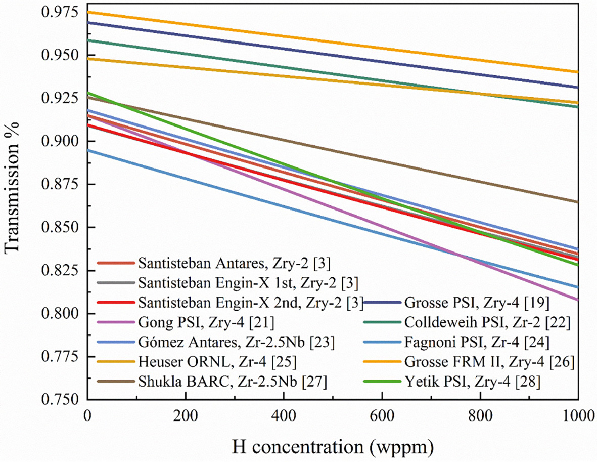
Numerous quantitative studies on hydrogen in zirconium alloys have shown that the calibration formulas used may exhibit minor deviations from Equation (4) when applied as calibration curves. In this review, experimental data are organized according to Equation (4), assuming a sample thickness of 4 mm unless otherwise specified. Figure 2 shows that the relationship between transmission and hydrogen concentration is nearly linear in the range of 0-1,000 wppm. The intercept indicates the absence of hydrogen in the material, while the slope reflects the sensitivity of the material to neutrons. Variations in material properties affect both the initial neutron transmission and the attenuation caused by hydrogen. Likewise, changes in material thickness influence its sensitivity to hydrogen. This conversion formula facilitates the description of hydrogen distribution and concentration in metals and hydrogen storage systems.
The attenuation coefficient is an intrinsic property of the material and is related to the neutron energy E or the equivalent neutron wavelength λ. For zirconium hydride, when λ 0.2 Å, its incoherent scattering behaves as the inelastic scattering of nearly free protons, and the attenuation coefficient remains basically constant. As the wavelength increases, oscillations appear. The thermal neutron interaction in zirconium hydride (ZrHx) is dominated by the dynamics of bound hydrogen in the lattice, primarily through incoherent inelastic scattering from hydrogen. Its characteristics are determined by the vibrational modes of hydrogen in the lattice (acoustic and optical branches)[17]. For λ 3 Å, the attenuation of hydrogen strongly depends on temperature due to the inelastic scattering process in which neutrons gain energy during collisions[3]. Under identical testing conditions, variations in the attenuation coefficient for hydrogen concentration between different materials are primarily governed by disparities in hydrogen density within their hydride phases. For instance, titanium, which has a similar crystal structure to zirconium, exhibits distinct macroscopic cross sections at the same hydrogen concentrations[13]. Consequently, material-specific calibration procedures are essential during quantitative measurements. These wavelength-related characteristics provide more evidence for the precise detection of hydrides. For instance, by choosing a neutron beam of an appropriate wavelength for the experiment, the presence and distribution of hydrides can be detected more sensitively[3]. The primary source of variation in the attenuation coefficients of different hydride phases is the disparity in hydrogen density. Under identical conditions, hydride phases with higher hydrogen density exhibit stronger neutron attenuation and higher attenuation coefficients. This difference is crucial in practical research. For example, in the analysis of zirconium alloys containing different hydride phases, variations in hydrogen density can lead to significant differences in neutron imaging results[7]. By measuring and analyzing the attenuation coefficient, both the presence and concentration of different hydride phases can be inferred.
HYDROGEN IN METALLIC STRUCTURAL MATERIALS
Zirconium alloys
Zirconium alloys are widely employed as nuclear fuel cladding tubes and pressure tubes in reactor systems due to their exceptional corrosion resistance and neutron transparency. Under in-service conditions, these alloys are subject to waterside corrosion when exposed to coolants, generating hydrogen that penetrates through the protective oxide layer and into the matrix. As hydrogen accumulates at the cladding surface, it exceeds the local solubility limit, leading to hydride precipitation. This process significantly compromises the mechanical integrity of the cladding by inducing embrittlement and volume expansion, which increases the risk of nuclear fuel leakage. Therefore, investigating the behavior of hydrogen dissolution and diffusion in zirconium alloys is crucial for predicting the thresholds for hydride formation, optimizing cladding performance, and ensuring the operational safety of nuclear reactors. Neutron imaging has become an essential tool in addressing critical issues such as hydrogen diffusion and HID in zirconium alloys, offering unique advantages due to its sensitivity to light elements, strong penetration capabilities, and non-destructive detection methods[2]. The characterization of hydrogen in zirconium using neutron beams was first validated by Bennun et al.[33] through neutron cross section measurements, diffraction studies[10], and imaging experiments on zirconium alloys and hydrides conducted between 1995 and 2004, as shown in Figure 3A-C[34-36]. The pioneering work by Grosse et al. further demonstrated the potential of neutron imaging for in-situ studies under high-temperature conditions, providing qualitative characterizations of hydrogen pickup and redistribution processes[37,38]. These studies examined hydrogen diffusion at elevated temperatures, steam oxidation dynamics, and Loss of Coolant Accidents (LOCA), highlighting the technique’s advancement in hydrogen detection, achieving high hydrogen concentrations up to
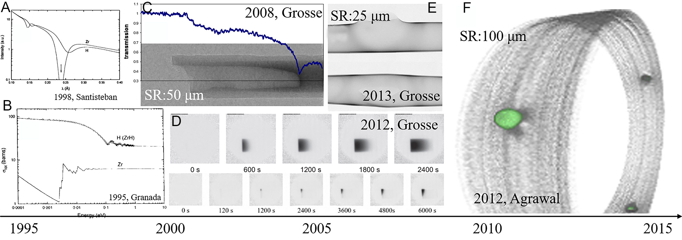
Figure 3. Neutron imaging development from 1995 to 2015: (A) the neutron scattered time of flight spectra by H and Zr[35], (B) cross sections of Zr and H in ZrH alloy[34], (C) neutron images of Zr-1Nb rod[23], (D) hydrogen diffusion at 1,273 K and 823 K in Zr-4[39], (E) 3D volume of pressure tube with blisters[37], (F) 3D tomography of the hydride blister in Zr-2.5Nb[43].
Grosse et al. found the linear association between neutron cross section and hydrogen concentration between 2008 and 2014. Although the relationship is subject to the influence of multiple factors, it establishes the physical foundation for quantitative neutron imaging[23]. Agrawal et al. transitioned from qualitative observation to quantitative application in zirconium hydride research, achieving a detection accuracy of 25 wppm[43]. Smith et al. rebuilt three-dimensional hydrogen distributions in Zr-4 alloys subjected to temperature gradients (13-1,096 wppm) to illustrate temperature-induced hydrogen segregation mechanisms as in Figure 4A[44].
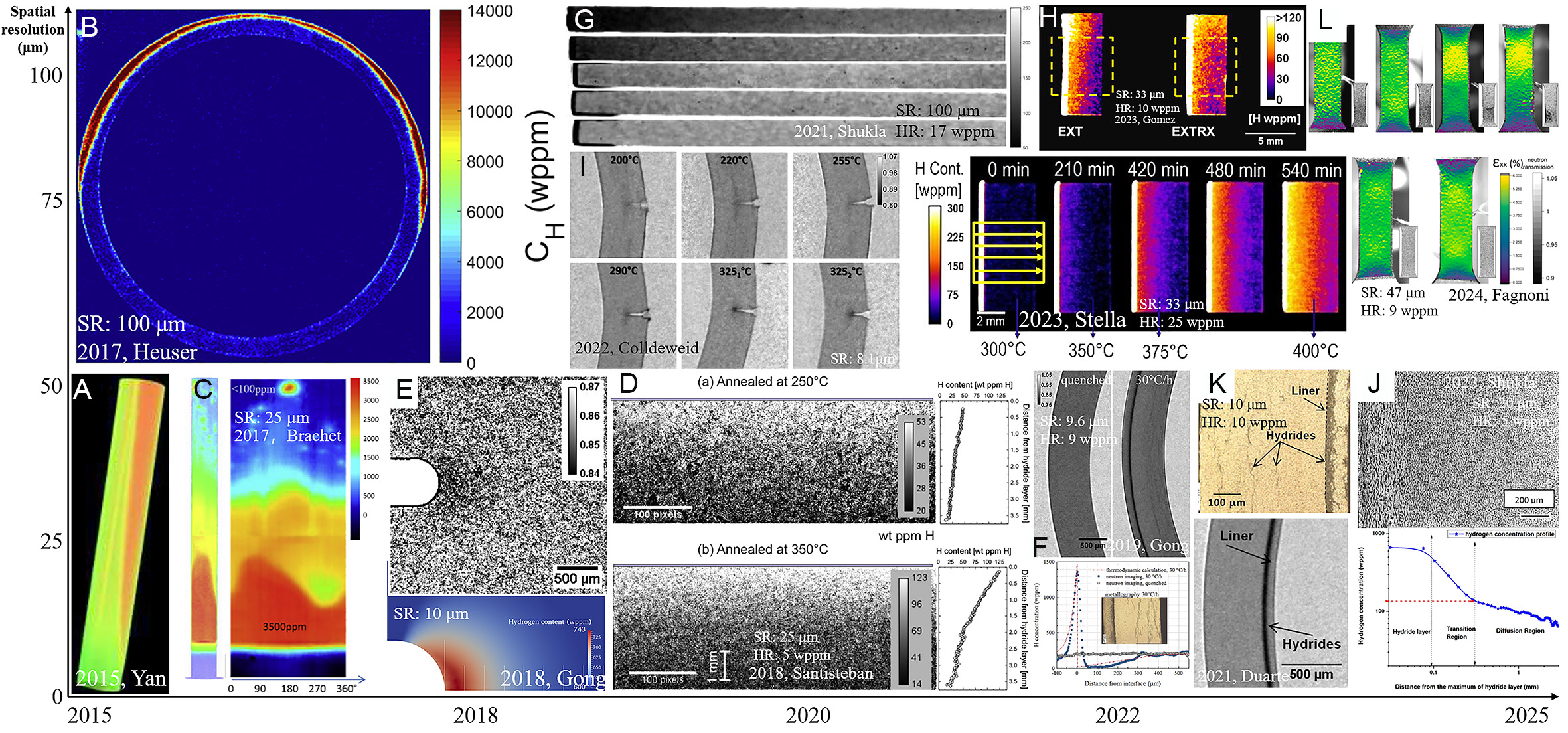
Figure 4. Neutron imaging resolution of hydrogen in Zr alloys optimizing with time: (A) 3D uneven hydrogen distribution in Zr-4[45], (B) hydrogen concentration of hoop stress tube[29], (C) tomographic hydrogen concentration distribution of clad segment[45], (D) hydrogen concentration in two inhomogeneous Zr-2.5Nb[3], (E) transmission of thermo-mechanical tested Zr-4 and stress field near the notch[46], (F) transmission imaging of the duplex cladding tubes[25], (G) annealed Zr-2.5Nb for displaying hydrogen diffusion[31], (H) hydrogen concentration maps for samples after annealed[27], (I) DHC in Zr-2 with integral 200 wppm hydrogen[26], (J) optical micrograph of Zr-2.5Nb annealed samples for diffusion rate and hydrogen concentration obtained by quantitative neutron imaging[32], (K) transmission imaging of the images of Zr-2 based cladding[49], (L) strain and hydrogen distribution maps of Zr-4 tensile samples[51].
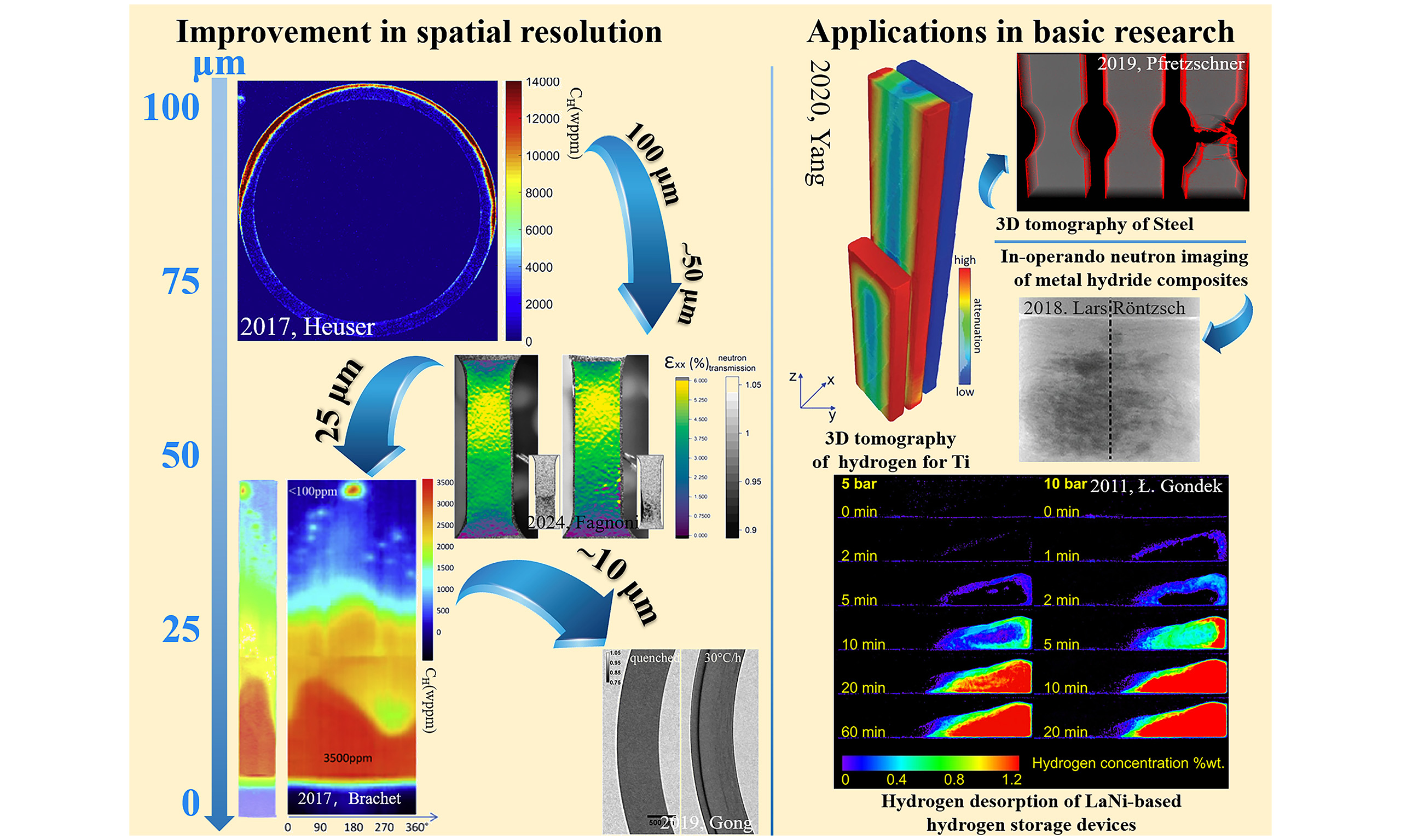
The resolution of pictures and the sensitivity to hydrogen were improved between 2015 and 2020. Brachet took 25 μm photos of clad hydrogen pick up in LOCA in Figure 4B and 4C. Heuser, on the other hand, employed 100 μm resolution imaging to explore stress-induced anisotropic hydrogen diffusion under hoop stress[29,45]. A milestone emerged in 2018 when Santisteban integrated multi-beamline data to achieve 25 μm spatial resolution and hydrogen resolution (HR) of 5 wppm, proving the technique’s reliability for low-concentration samples (< 10 wppm) in Figure 4D[25]. Meanwhile, Gong attained 10 μm spatial resolution and 9 wppm in sensitivity [Figure 4E and F] in hydrogen diffusion studies under stress and chemical potential gradient, enabling hydrogen behavior analysis at micron-scale level and in 2022 revealed the influence of stress-driven conditions on hydride precipitation, demonstrating the inhibitory effect of compressive stress on hydride formation[3,25,46]. Additionally, the results of finite element modeling (FEM), which analyzes stress distribution, can demonstrate the distribution states of tensile and compressive stress. The hydride redistribution integrates with stress distribution, better corroborating the interactive effect of tensile and compressive stresses during hydride formation[47].
In the past five years, breakthroughs in neutron imaging have significantly advanced the quantitative characterization of hydrogen behavior in metallic systems, particularly in terms of spatial resolution, detection sensitivity, and multi-physics coupling. One notable example is Shukla’s pioneering high-resolution diffusion studies, which achieved a spatial resolution of 100 μm and a hydrogen detection limit of 17 wppm. These advances enabled accurate tracing of hydrogen diffusion rates. Neutron imaging also revealed fine-scale hydrogen gradients [Figure 4G], providing five times more data compared to conventional metallography[31]. In 2023, Gómez et al. & Stella et al. improved dynamic hydrogen monitoring by achieving a spatial resolution of 33 μm and a hydrogen quantification sensitivity of 10-25 wppm. This advancement enabled direct observation of hydrogen migration during diffusion cycles [Figure 4H][27,48]. Furthermore, in the context of microscale hydrogen-induced delayed hydride cracking (DHC), Colldeeweih reached an unprecedented spatial resolution of 8.1 μm, allowing micron-scale visualization of hydrogen aggregation fronts [Figure 4I][26]. Weick & Grosse pushed spatial resolution below 10 μm with hydrogen quantification limitation approaching a few wppm, setting new benchmarks for nanoscale hydrogen mapping[7]. The quantification limitation improvement achieved by Shukla employed advanced signal processing algorithms to as low as 5 wppm, enhancing sensitivity for low-concentration hydrogen analysis in complex alloys in Figure 4J[32]. Multi-physics coupling capabilities in hydrogen quantitative characterization: Duarte et al. combined 10 μm spatial resolution with 10 wppm hydrogen quantification resolution to uncover interface-induced hydrogen diffusion barriers in Zr-2 alloys, linking microstructural features to hydrogen trapping efficiency in Figure 4K[49]. In 2023, Konarski et al. further characterized such diffusion barriers using neutron imaging and developed a modeling approach, which clearly revealed hydrogen diffusion, hydride dissolution/precipitation, and the hydrogen solubility difference between the substrate and liner[50]. In addition, Fagnoni et al. integrated hardness mapping in 9.6 μm resolution and hydrogen-strain field synchronization (47 μm/9 wppm) to correlate hydrogen distribution quantitatively with mechanical degradation during plastic deformation, offering mechanistic insights into HE
In the advancement of neutron imaging technology, improvements in scintillator materials and upgrades in detector design have played a pivotal role. The new scintillator 157Gd2O2S:Tb, combined with iridium coating materials, can improve light output efficiency while maintaining resolution and neutron absorption capacity[52]. Moreover, enlarging the numerical aperture of magnifying optical instruments can improve resolution by 30%, attaining a spatial resolution of 5 μm[53]. Recent studies indicate that a high numerical aperture enhances spatial resolution, whereas variable optical magnification mitigates inelastic and incoherent Moiré effects arising from varying pixel sizes for distinct events[54].
In 2013, LOCA simulations highlighted the trade-off between short exposure times (2 min) and spatial resolution degradation, with ex-situ studies achieving 100 μm, whereas in-situ studies reached 25 μm, as shown in Figure 5A. Subsequent optimization of the optical system enabled in-situ oxidation monitoring at 25 μm spatial resolution[40]. Grosse et al. further demonstrated the non-destructive advantage of neutron imaging by dynamically characterizing hydrogen distributions under coupled mechanical stress-thermal-gas field conditions at 350 °C, achieving a spatial resolution of 25 μm in Figure 5B[55]. However, increasing the sample-detector distance to 225 mm was found to degrade the resolution to 250 μm [Figure 5C][56], emphasizing the importance of optimized beamline design in multi-physics experiments. By 2023,
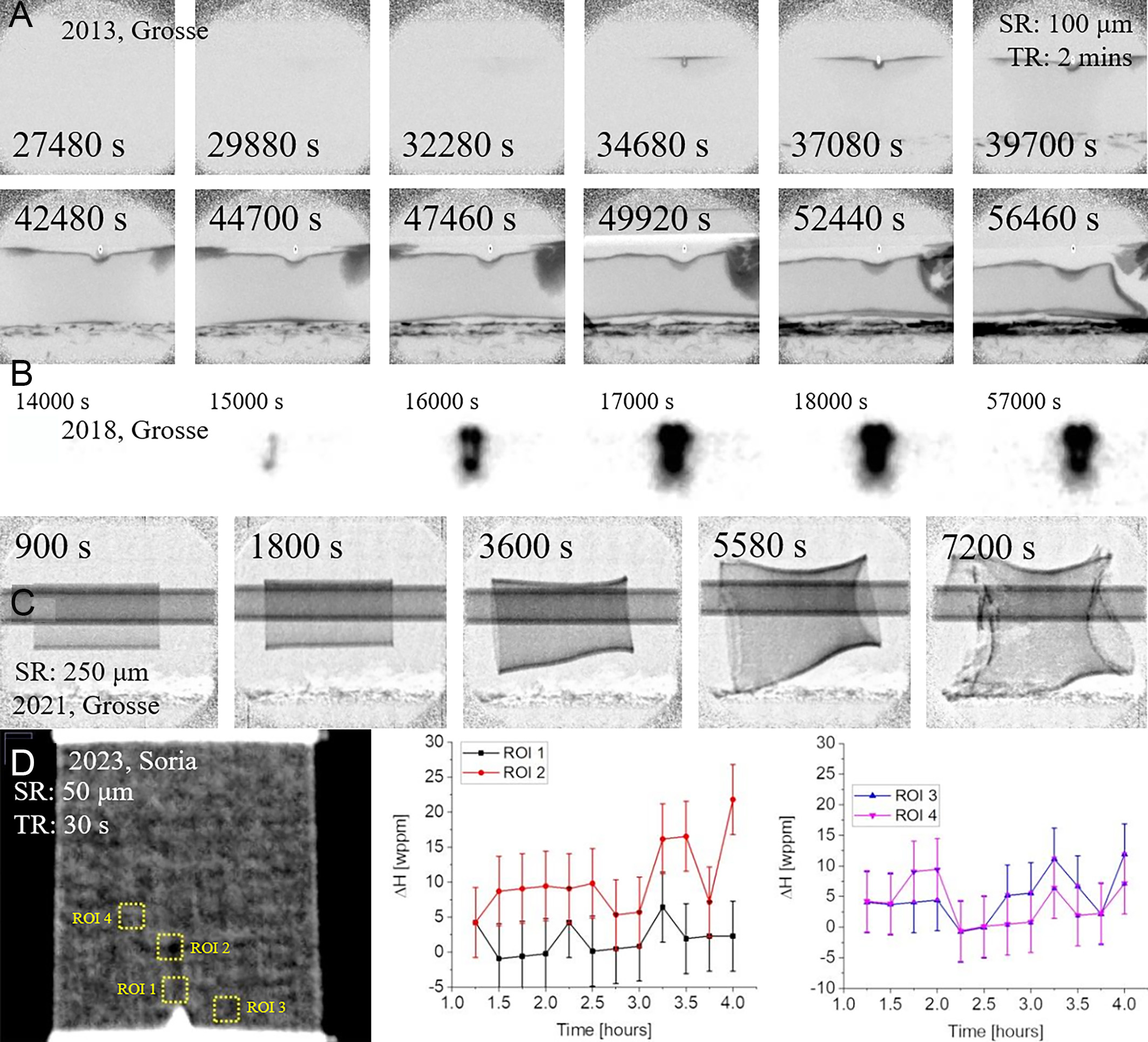
Figure 5. In-situ neutron imaging of Zr alloys: (A) mechanical stress-Ar/H2 and 350 °C conditions coupling for Zr-4[38], (B) mechanical stress-inert annealing in Ar/H2 at 350 °C for hydrogen diffusion[55], (C) nitrogen/steam atmosphere for Zr-4 swelling[56], (D) end image of in-situ DHC test for Zr-2.5Nb[57].
In summary, neutron imaging technology has advanced rapidly. Continuous improvements in in-situ characterization equipment have enabled precise control of stress and temperature during experiments, while also significantly enhancing image quality and hydrogen detection resolution[59]. Spatial resolution has improved more than 30-fold, from above 100 μm in 2008 to below 10 μm in 2024, and hydrogen detection limits have decreased fivefold, from 25 wppm to less than
Titanium alloys
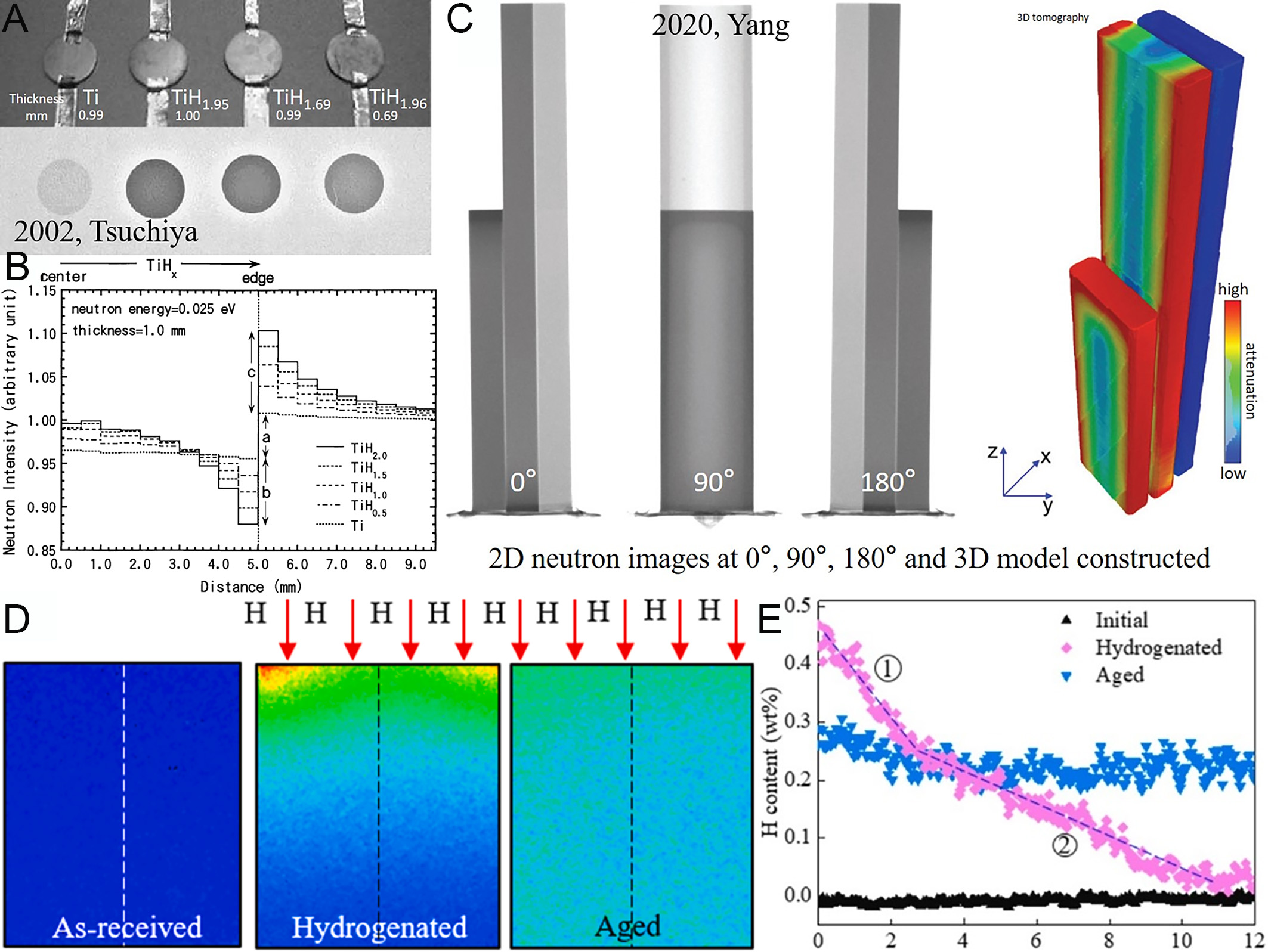
Titanium, extensively applied in aerospace, biomedical engineering, marine exploration, and the nuclear industry[61-64], exhibits hydride formation behaviors similar to those observed in zirconium alloys. Hydrogen in titanium alloys degrades mechanical properties through the formation of hydride phases[65]. However, targeted heat treatments can partially restore mechanical performance. These thermal processes facilitate hydrogen desorption while promoting the dissolution and redistribution of hydride phases. Therefore, understanding hydrogen distribution and diffusion kinetics in titanium alloys is crucial for optimizing post-hydrogenation recovery strategies and ensuring structural reliability[66]. The relatively low neutron cross-section of titanium further enhances its suitability for neutron imaging studies[2]. Initial experiments on titanium hydrides in 2002 demonstrated a systematic decrease in neutron transmission with increasing hydrogen concentration, accompanied by edge effects, wherein peripheral regions exhibited higher brightness compared to central areas and background. These effects intensified with increasing hydrogen content as shown in Figure 6A and B[67]. In 2020, 3D neutron tomography enabled quantitative characterization of hydrogen gradient distributions in titanium alloys, revealing higher hydrogen concentrations at surfaces compared to interiors and dynamically tracking hydrogen diffusion pathways during thermal hydrogenation processing (THP) [Figure 6C][68]. By 2025, neutron imaging elucidated the dominant role of β-phase in early-stage hydrogen diffusion, with rapid hydrogen migration through β-phase channels resulting in non-uniform distribution at diffusion fronts. Quantitative comparisons of hydrogen concentrations before and after aging treatments [Figure 6D and E] provided experimental evidence of phase-transition-diffusion coupling mechanisms in titanium-hydrogen systems[69]. Kumar et al.’s 2025 study further characterized the radial uniformity of hydrogen distribution and the decreasing concentration gradient from surface to interior in hydrided titanium alloys during corrosion, demonstrating that MgZnCa coverage at the center impedes hydrogen diffusion[70]. Thermal neutrons (energy < 0.5 eV) and cold neutrons (energy < 5 meV) can be employed for imaging metallic materials at a centimeter scale or smaller. With technological advancements, neutron imaging has progressed from qualitative observations to a multiscale, quantitative analytical tool[71].
Future research should integrate neutron imaging with phase-field simulations and synchrotron-based characterization to elucidate the dynamic evolution of titanium hydrides. Such multimodal approaches will connect mesoscale hydrogen distribution patterns with atomic-scale structural changes, ultimately enabling predictive modeling of hydrogen-induced degradation in titanium alloys under service conditions.
Steels
Steel components operating in hydrogen-rich environments, such as hydrogen storage tanks, absorb hydrogen through mechanisms involving hydrogen transport, stress fields, and localized accumulation, resulting in significant deterioration of mechanical properties[72]. During welding, hydrogen dissociated from protective gases diffuses into the weld pool and becomes trapped upon solidification. When hydrogen exceeds local solubility limits, material degradation accelerates markedly. The combined influence of hydrogen and stress on defects promotes crack initiation and propagation, a phenomenon particularly pronounced in high-strength alloys. In these materials, hydrogen segregation at grain boundaries and precipitates substantially reduces fracture toughness, facilitating crack growth. A comprehensive understanding of these hydrogen-material interactions is therefore essential for optimizing welding protocols and developing effective corrosion mitigation strategies[73]. HE in steels arises from the synergistic effects of lattice-dissolved hydrogen and hydrogen trapped at microstructural sites such as dislocations, grain boundaries, and carbide particles. Resolving these mechanisms critically depends on mapping hydrogen spatial distributions, a task for which neutron imaging offers unique advantages due to its non-destructive and hydrogen-specific detection capabilities[74]. In 2011, neutron imaging was first applied to study hydrogen effusion rates in austenitic stainless steel[75]. By integrating a heating unit, this study achieved synchronous in-situ monitoring of hydrogen concentration and temperature, overcoming the limitations of conventional carrier gas hot extraction (CGHE), which only measures lattice-diffusible hydrogen [Figure 7A and B]. Subsequent work in 2013 further validated the technique’s ability to capture cavity-trapped hydrogen[76], offering a novel approach to investigate multi-state hydrogen interactions.
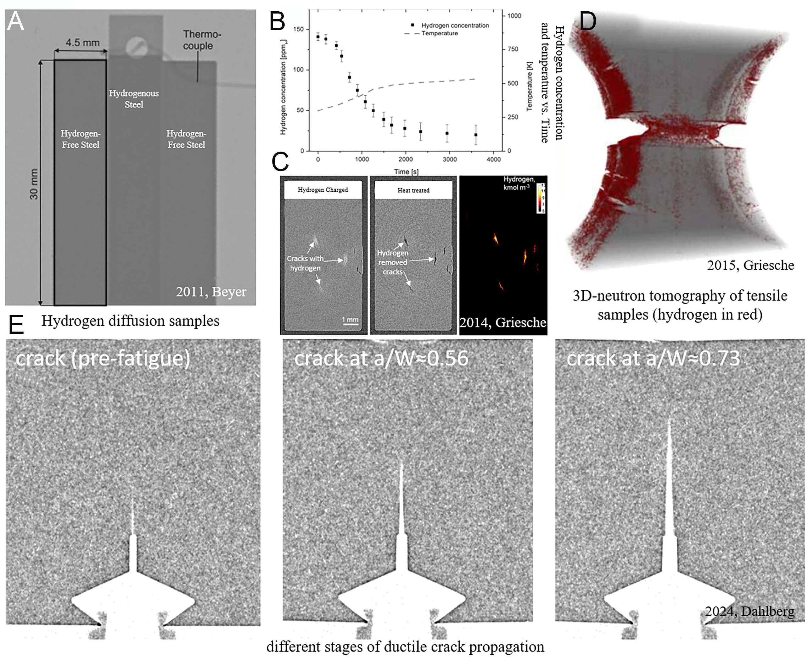
Figure 7. Neutron images of steels: (A) neutron images of hydrogenous and hydrogen-free steels[75], (B) Hydrogen concentration change with time and temperature[75], (C) hydrogen in cracks before and after heat treatment[73], (D) 3D tomography of martensitic tensile sample (hydrogen in red)[79], (E) different stages of ductile crack propagation[72].
In the characterization of hydrogen-induced cracks, neutron imaging non-destructively reveals crack morphology and internal hydrogen retention. Studies on steels with high hydrogen concentrations show persistent hydrogen signals within internal cracks even after thermal treatment, providing insights into hydrogen distribution and crack geometry [Figure 7C][73,77,78]. Tensile experiments on austenitic and martensitic stainless steels further demonstrate hydrogen accumulation in stress-concentrated regions
SOLID-STATE HYDROGEN STORAGE MATERIALS
Solid-state hydrogen storage materials, which offer a promising solution for safe and efficient hydrogen storage, have garnered significant attention in recent years[80]. These materials are generally capable of reversibly absorbing and desorbing hydrogen, rendering them ideal candidates for applications in fuel cells and other hydrogen-powered technologies. A critical challenge, however, lies in fully understanding the hydrogen evolution behavior within these storage materials - a problem particularly well-suited for investigation using neutron imaging[81]. The design of neutron imaging systems for hydrogen storage materials requires careful consideration of factors such as neutron flux, spatial resolution, and the experimental chamber, which must accommodate the high-pressure environments typical of hydrogen storage conditions. Furthermore, neutron imaging can be integrated with complementary techniques, such as X-ray imaging and thermal analysis, providing a more comprehensive understanding of material behavior under varied operating conditions. Beyond microscopic studies, neutron imaging also informs the design and optimization of hydrogen storage tanks and enables the examination of entire hydrogen tanks filled with storage materials.
In hydrogen storage alloys, Sakaguchi et al. employed neutron radiography (NRG) and neutron computed tomography (NCT) to visualize hydrogen distribution in the hydrogenated solid solution of Mg-Ni alloys. The studies revealed that Mg3Ni was more prone to pulverization compared to Mg2Ni due to the formation of the MgH2 phase[82,83]. These investigations provided both qualitative and quantitative insights into hydrogen absorption [Figure 8] and the desorption kinetics of LaNi-based hydrogen storage materials within specific storage devices, offering valuable guidance for industrial design and the future application of onboard hydrogen storage tanks[84-86]. In metal hydrides, Garlea demonstrated that NRG effectively captures LiH behavior, including its hydrolysis products and the thermal conversion of LiOH to Li2O[87]. Similarly, Röntzsch employed neutron imaging to study the structural stability and spatiotemporal hydrogen concentration in graphite-containing metal hydride composites (MHC) with diameters of 40 mm. This approach allowed observation of reaction fronts within the MHC and powder bed, which were strongly influenced by heat transfer[88]. Börries further established the utility of neutron imaging for precise quantitative analyses of time-dependent hydrogen distribution in metal hydride systems, exemplified through investigations of sodium alanate inside hydrogen storage tanks[89]. For composite systems, the LiBH4-MgH2 system, with and without ScCl3 additives, was characterized using both synchrotron- and neutron-based probing methods, providing complementary insights into the hydride matrix[90]. Furthermore, neutron tomography of a hydrogen storage tank filled with NaAlH4/TiF3 was employed to demonstrate the hydrogenation process and the distribution of hydrides within the composite hydride system in the tank[91].
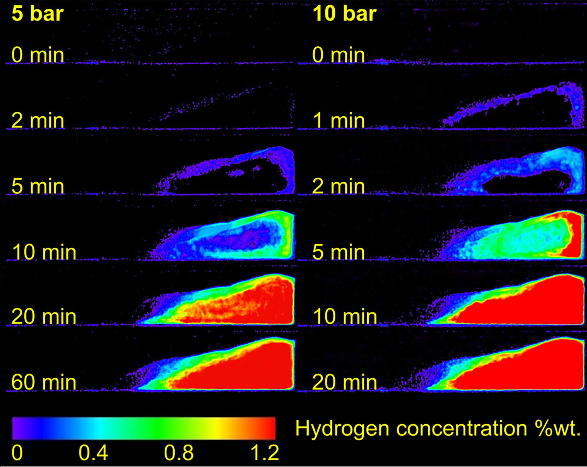
Figure 8. Neutron images of hydrogenating process kinetics at different pressures[85].
In addition to studies on hydrogen storage materials, neutron imaging has proven to be a critical tool for visualizing the internal states of large-scale hydrogenated containers and informing the design of efficient hydrogen storage tanks[92]. The optimization of such tanks necessitates precise, time-resolved investigations of hydrogen distribution within large-scale metal hydride beds. In this context, researchers have proposed that in-situ fission neutron imaging can provide unique insights into hydrogen spatial distributions, enabling direct examination of hydrogen storage tanks even in large-scale compact configurations[93].
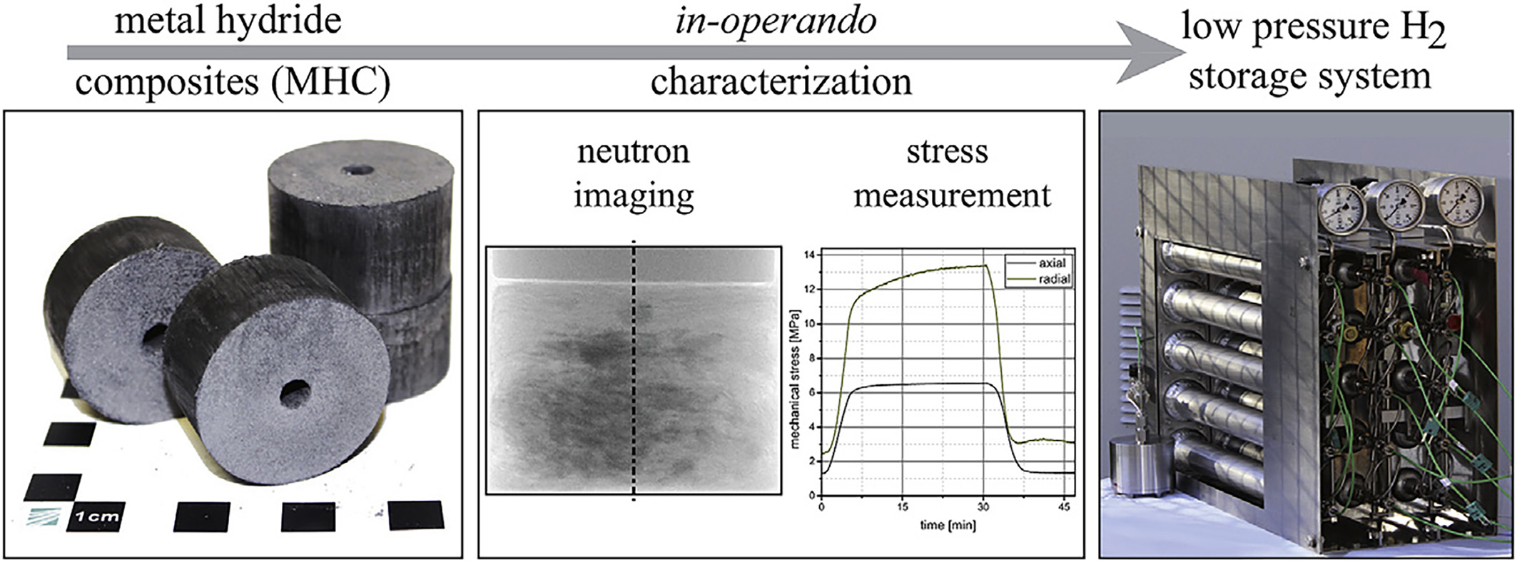
Figure 9. In-operando characterization of the volume expansion and mechanical stress measurement of MHC for the design of safe metal hydride storage systems[96].
BLACK BODY GRID CORRECTION OF BACK SCATTERING NEUTRON
In the quantitative determination of hydrogen concentration, data processing reveals spatially inconsistent air transmission profiles, as obtained using Equation (2) and illustrated in Figure 10A. To systematically assess this phenomenon, a width of 0.2 mm along a diagonal path from the upper-left to the lower-right of the image was analyzed, deliberately avoiding regions influenced by the sample to isolate background effects. The measured transmission exhibited an initial increase followed by a slight decrease [Figure 10B], a trend attributed to background scattering caused by the presence of the sample rather than to edge effects. Specifically, neutron beams passing near the sample edges interact with post-imaging optical components, such as mirrors, and scatter back toward the scintillator screen, generating extraneous counts across the entire image. This effect alters the recorded counts from the sample itself and was first identified by Hassanein et al.[97], introducing systematic biases in hydrogen quantification.
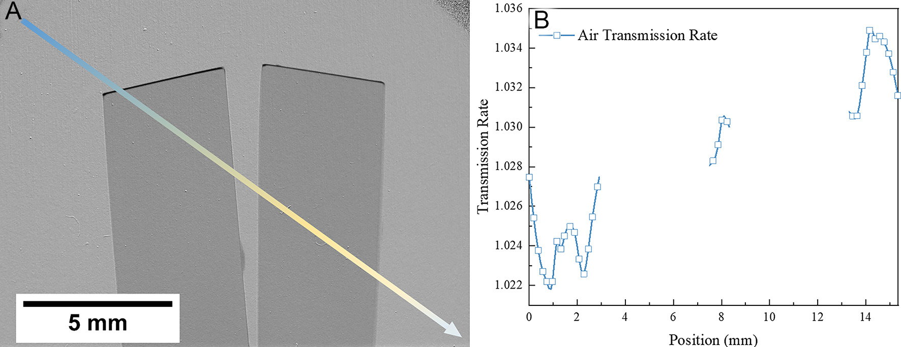
Figure 10. (A) The diagonal path and region of interest (ROIs); (B) the air transmission of 7 ROIs.
Boillat et al.[98] proposed a correction method employing a black body grid to address this issue. The protocol involves two steps: firstly, grid-only reference images use a grid framework consisting of the high transmission material as a cross grid with low transmission material in the junctions [Figure 11A]. Secondly, sample and grid composite images are the measurements combining the sample and grid to isolate backscattering neutron contributions. The absorbers occupy only 0.8% of the total imaging area, minimizing beam attenuation while enabling full-field characterization of the point spread function (PSF) [Figure 11B]. The deconvolution correction was applied to the entire image using the measured PSF, reconstructing bias-free transmission profiles [Figure 11C].
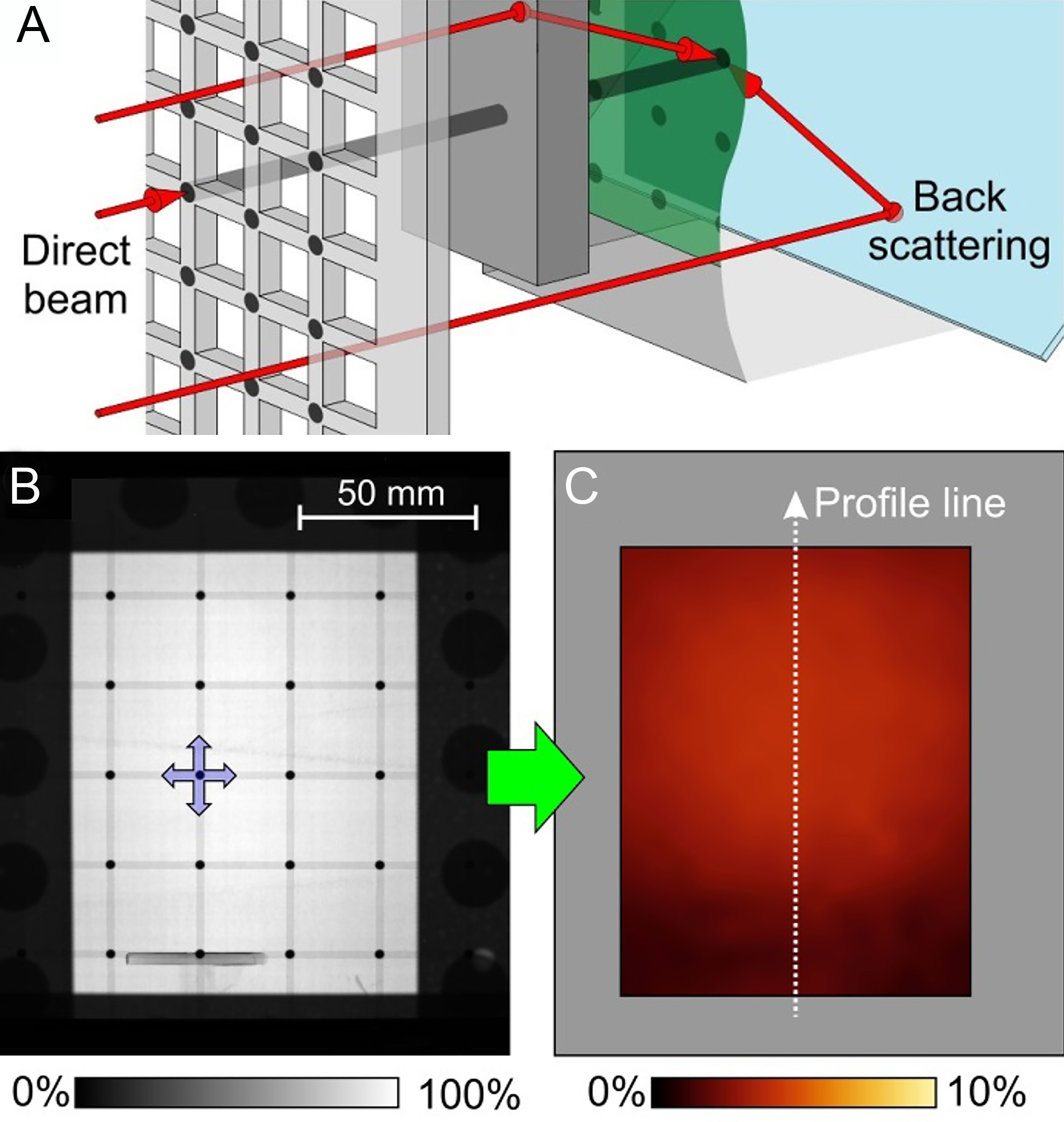
Figure 11. (A) The schematic of black body grid and the back scattering neutron; (B) measurement of black body grid; (C) resulting interpolated background image by the black body grid[98].
Yetik et al. advanced quantitative neutron imaging methodology by integrating a black body grid into hydrogen redistribution studies[99]. This approach employs a high-transmission substrate, such as aluminum, embedded with periodic, uniformly distributed low-transmission circular absorbers across both the sample area and background in the same image[99]. Background intensity variations are observed in regions unaffected by neutron scattering, with background intensities at approximately 2% of the nominal beam flux, while in affected regions, intensities increase to 4%. Prior to deconvolution correction, an additional 2% intensity bias arises, further compounding quantification errors. Post-processing corrections for backscattered neutron contributions, yielding transmission correction magnitudes between 0.264% and 2.603%, were implemented using the software KipTool[100]. In 3D tomography, precise alignment of the black body grid with the sample is crucial to minimize thickness-dependent biases, particularly for low-transmission samples such as hydrogen-rich alloys, high-thickness materials, or elements of relatively high atomic mass. These corrections are essential because transmission fluctuations within this range caused by factors unrelated to hydrogen concentration can significantly distort quantitative analysis, especially for hydrogen concentrations below 1,000 wppm.
Although neutron imaging has achieved spatial resolutions of ~10 μm, this remains approximately three orders of magnitude lower than that of synchrotron X-ray imaging, which can reach resolutions as fine as ~30 nm. While optical paths can be readily adjusted for X-rays using lenses, collimation of neutron beams is inherently challenging, limiting their achievable spatial resolution. Temporal resolution is similarly constrained: time-resolved synchrotron radiation can acquire 8,000 projection images within 1-2 s[101], whereas neutron imaging typically requires one minute to three hours per complete image. Each neutron image results from averaging and stacking multiple filtered data points, and successive data collection periods are needed to ensure neutron beam stability, further extending experimental durations.
These limitations arise primarily because neutrons interact randomly with atomic nuclei, resulting in multiple scattering events that cause image blurring. Additionally, the photon flux of synchrotron X-rays can reach up to 1012 ph/cm2/s[102], which is 6-8 orders of magnitude higher than typical neutron fluxes
SUMMARY AND FUTURE DIRECTIONS
Due to its non-destructive nature, high penetrability, and exceptional sensitivity to hydrogen, neutron imaging has emerged as a powerful tool for the quantitative analysis of hydrogen diffusion and distribution in metallic materials. The methodology is grounded in the Beer-Lambert law, which relates the microscopic cross-section of a material to its hydrogen concentration, forming the theoretical foundation for quantitative characterization. Ex-situ and in-situ studies have demonstrated the capability of high-resolution neutron imaging to resolve hydrogen distribution with remarkable precision. In particular, in-situ investigations of hydrogen absorption and desorption kinetics in hydrogen storage materials, coupled with the development of dedicated characterization equipment, have enabled detailed monitoring of dynamic processes in real time. Advancements in imaging instrumentation, alongside improvements in data processing techniques, have further enhanced spatial resolution and hydrogen quantification accuracy.
Despite these achievements, several challenges remain in optimizing neutron imaging for hydrogen detection in metals and hydrogen storage materials. Future research directions include the development of enhanced neutron monitoring systems to improve imaging precision and hydrogen sensitivity, particularly within large or complex experimental setups. Integrating neutron imaging with complementary characterization techniques, such as differential scanning calorimetry (DSC), will provide more comprehensive insights into solid-state hydrogen storage phenomena. Additionally, establishing a standardized, cross-facility database that documents neutron beam parameters, sample thickness, material composition, and transmission data will be critical for enabling reproducible experiments and robust data sharing. Collectively, these advancements are expected to improve the descriptive characterization of hydrogen behavior, enhance detection capabilities, and optimize the design and performance of hydrogen storage technologies.
DECLARATIONS
Authors’ contributions
Writing - original draft, investigation, data curation, supervision, conceptualization: Zhang, M.
Writing - language revision: Muzamil, N.; Que, Z.
Writing - original draft, investigation, data curation: Jia, Y.; Zhang, X.
Resources, data curation: Sun, Y.; Chen, J.; Yang, L.
Writing - review and editing, project administration, supervision, conceptualization: Gong, W.
Availability of data and materials
All figures and data are from public literature with details provided in the citations except Figure 10. Figure 10A is derived from the research program and is not currently authorized for public release.
Financial support and sponsorship
This work is funded by the National Key R&D Program of China for Young Scientists (2023YFA1610300) and the National Natural Science Foundation of China (NASF U2230124, 12005170).
Conflicts of interest
All authors declared that there are no conflicts of interest.
Ethical approval and consent to participate
Not applicable.
Consent for publication
Not applicable.
Copyright
© The Author(s) 2025.
REFERENCES
1. Kardjilov, N.; Manke, I.; Woracek, R.; Hilger, A.; Banhart, J. Advances in neutron imaging. Mater. Today. 2018, 21, 652-72.
2. Kardjilov, N.; Manke, I.; Hilger, A.; Strobl, M.; Banhart, J. Neutron imaging in materials science. Mater. Today. 2011, 14, 248-56.
3. Buitrago, N.; Santisteban, J.; Tartaglione, A.; et al. Determination of very low concentrations of hydrogen in zirconium alloys by neutron imaging. J. Nucl. Mater. 2018, 503, 98-109.
4. Strickland, J.; Tassenberg, K.; Sheppard, G.; et al. 2d single crystal bragg-dip mapping by time-of-flight energy-resolved neutron imaging on IMAT@ISIS. Sci. Rep. 2020, 10, 20751.
5. Woracek, R.; Santisteban, J.; Fedrigo, A.; Strobl, M. Diffraction in neutron imaging - A review. Nucl. Instrum. Methods. Phys. Res. Sect. A. 2018, 878, 141-58.
6. Muneem, A.; Yoshida, J.; Saito, T. R.; et al. Advancing neutron imaging techniques to highest resolution with fluorescent nuclear track detectors. Sci. Rep. 2025, 15, 2103.
7. Weick, S.; Grosse, M. Investigating hydrogen in zirconium alloys by means of neutron imaging. Materials 2024, 17, 781.
8. Aswal, D. K.; Sarkar, P. S.; Kashyap, Y. S. Neutron imaging: basics, techniques and applications. Springer, 2022.
9. Strobl, M.; Manke, I.; Kardjilov, N.; Hilger, A.; Dawson, M.; Banhart, J. Advances in neutron radiography and tomography. J. Phys. D. Appl. Phys. 2009, 42, 243001.
10. Grosse, M.; Kardjilov, N. Which resolution can be achieved in practice in neutron imaging experiments? Phys. Proc. 2017, 88, 266-74.
11. Brenizer, J. A review of significant advances in neutron imaging from conception to the present. Phys. Proc. 2013, 43, 10-20.
12. Wang, S.; Shi, H.; Wang, D.; et al. Neutron-based characterization: a rising star in illuminating rechargeable lithium metal batteries. Nano. Energy. 2024, 122, 109337.
13. Börries, S. Neutron imaging of metal hydride systems; 2017. Available from: https://ediss.sub.uni-hamburg.de/handle/ediss/7425 [Last accessed on 18 Sep 2025].
14. Lehmann, E. H.; Vontobel, P.; Kardjilov, N. Hydrogen distribution measurements by neutrons. Appl. Radiat. Isot. 2004, 61, 503-9.
15. Bilheux, H. Z.; McGreevy, R.; Anderson, I. S. Neutron imaging and applications: a reference for the imaging community; Springer, 2009.
16. Banhart, J. Advanced tomographic methods in materials research and engineering. OUP Oxford; 2008.
17. Mattes, M.; Keinert, J. Thermal neutron scattering data for the moderator materials h2o, d2o and ZrHx in ENDF-6 format and as ACE library for MCNP(X) codes. Vienna: IAEA Nuclear Data Section; 2005. Available from: https://library.iaea.org/permalink/43IAEA_INST/2q130i/alma991000004629709096 [Last accessed on 18 Sep 2025].
18. Grammer, K. B.; Alarcon, R.; Barrón-palos, L.; et al. Measurement of the scattering cross section of slow neutrons on liquid parahydrogen from neutron transmission. Phys. Rev. B. 2015, 91, 180301.
19. Romanelli, G.; Onorati, D.; Ulpiani, P.; et al. Thermal neutron cross sections of amino acids from average contributions of functional groups. J. Phys. Condens. Matter. 2021, 33, 285901.
21. Fritzsche, H.; Huot, J.; Fruchart, D. Neutron scattering and other nuclear techniques for hydrogen in materials. Springer, 2016.
22. Dawidowski, J.; Granada, J. R.; Santisteban, J. R.; et al. Neutron scattering lengths and cross sections. Neutron Scattering - Fundamentals. Elsevier; 2013. pp. 471-528.
23. Grosse, M.; Kuehne, G.; Steinbrueck, M.; Lehmann, E.; Stuckert, J.; Vontobel, P. Quantification of hydrogen uptake of steam-oxidized zirconium alloys by means of neutron radiography. J. Phys. Condens. Matter. 2008, 20, 104263.
24. Grosse, M.; Stuckert, J.; Steinbrück, M.; Kaestner, A. Secondary hydriding during LOCA - Results from the QUENCH-L0 test. J. Nucl. Mater. 2012, 420, 575-82.
25. Gong, W.; Trtik, P.; Colldeweih, A.; et al. Hydrogen diffusion and precipitation in duplex zirconium nuclear fuel cladding quantified by high-resolution neutron imaging. J. Nucl. Mater. 2019, 526, 151757.
26. Colldeweih, A. W.; Fagnoni, F.; Trtik, P.; Zubler, R.; Pouchon, M. A.; Bertsch, J. Delayed hydride cracking in Zircaloy-2 with and without liner at various temperatures investigated by high-resolution neutron radiography. J. Nucl. Mater. 2022, 561, 153549.
27. Gómez, A. G.; Ponce, J. P.; Grosse, M.; et al. Evaluation of the delayed hydrogen cracking behavior and the hydrogen diffusion coefficient for different microstructures of the Zr-2.5%Nb alloy. J. Nucl. Mater. 2023, 587, 154725.
28. Fagnoni, F.; Trtik, P.; Wheeler, J. M.; Zubler, R.; Bertsch, J.; Duarte, L. I. Hydrogen diffusion in zirconium cladding alloys with an inner liner as quantified by neutron radiography and nanoindentation. J. Nucl. Mater. 2023, 584, 154574.
29. Lin, J.; Zhong, W.; Bilheux, H. Z.; Heuser, B. J. Azimuthally anisotropic hydride lens structures in Zircaloy 4 nuclear fuel cladding: high-resolution neutron radiography imaging and BISON finite element analysis. J. Nucl. Mater. 2017, 496, 129-39.
30. Grosse, M.; van, den. Berg. M.; Goulet, C.; Lehmann, E.; Schillinger, B. In-situ neutron radiography investigations of hydrogen diffusion and absorption in zirconium alloys. Nucl. Instrum. Methods. Phys. Res. Sect. A. 2011, 651, 253-7.
31. Shukla, S.; Singh, P.; Roy, T.; Kashyap, Y.; Shukla, M.; Singh, R. Investigation of hydrogen diffusivity in Zr-2.5%Nb alloy pressure tube material using metallography and neutron radiography. J. Nucl. Mater. 2021, 544, 152679.
32. Shukla, S.; Singh, R.; Kashyap, Y.; et al. Anisotropy study of hydrogen diffusion along different directions of Zr-2.5%Nb alloy pressure tube using neutron imaging. J. Nucl. Mater. 2023, 580, 154414.
33. Bennun, L.; Santisteban, J.; Díaz-Valdés, J.; Granada, J.; Mayer, R. A neutronic method to determine low hydrogen concentrations in metals. Nucl. Instrum. Methods. Phys. Res. Sect. B. 2007, 263, 468-72.
34. Granada, J.; Santisteban, J.; Mayer, R. Non-destructive determination of very low hydrogen content in metals with the use of neutron techniques. Phys. B. 1995, 213-214, 1005-7.
35. Santisteban, J.; Granada, J.; Mayer, R. Neutron spectrometer for the determination of very low hydrogen content in metals. J. Neutron. Res. 1998, 7, 1-14.
36. Sváb, E.; Mészáros, G.; Somogyvári, Z.; Balaskó, M.; Körösi, F. Neutron imaging of Zr-1%Nb fuel cladding material containing hydrogen. Appl. Radiat. Isot. 2004, 61, 471-7.
37. Grosse, M. K.; Stuckert, J.; Steinbrück, M.; Kaestner, A. P.; Hartmann, S. Neutron radiography and tomography investigations of the secondary hydriding of zircaloy-4 during simulated loss of coolant nuclear accidents. Phys. Proc. 2013, 43, 294-306.
38. Grosse, M.; Valance, S.; Stuckert, J.; et al. Neutron imaging investigations of the hydrogen related degradation of the mechanical properties of zircaloy-4 cladding tubes. MRS. Proc. 2013, 1528, S1946427413003643.
39. Grosse, M.; van, den. Berg. M.; Goulet, C.; Kaestner, A. In-situ investigation of hydrogen diffusion in Zircaloy-4 by means of neutron radiography. J. Phys. Conf. Ser. 2012, 340, 012106.
40. Grosse, M.; Pulvermacher, S.; Steinbrück, M.; Schillinger, B. In-situ neutron radiography investigations of the reaction of Zircaloy-4 in steam, nitrogen/steam and air/steam atmospheres. Phys. B. 2018, 551, 244-8.
41. Grosse, M.; Roessger, C.; Stuckert, J.; et al. Neutron imaging investigations of the secondary hydriding of nuclear fuel cladding alloys during loss of coolant accidents. Phys. Proc. 2015, 69, 436-44.
42. Hong T, Brachet J, Crépin J, Le Saux M. Combined effects of temperature and of high hydrogen and oxygen contents on the mechanical behavior of a zirconium alloy upon cooling from the βZr phase temperature range. J. Nucl. Mater. 2021, 554, 153069.
43. Agrawal, A.; Kashyap, Y.; Sarkar, P.; et al. Study of hydride blisters in Zr-alloy using neutron tomography. J. Nucl. Mater. 2012, 421, 47-53.
44. Smith, T.; Bilheux, H.; Ray, H.; Bilheux, J.; Yan, Y. High resolution neutron radiography and tomography of hydrided zircaloy-4 cladding materials. Phys. Proc. 2015, 69, 478-82.
45. Brachet, J.; Hamon, D.; Le, Saux. M.; et al. “Study of secondary hydriding at high temperature in zirconium based nuclear fuel cladding tubes by coupling information from neutron radiography/tomography, electron probe micro analysis, micro elastic recoil detection analysis and laser induced breakdown spectroscopy microprobe. J. Nucl. Mater. 2017, 488, 267-86.
46. Gong, W.; Trtik, P.; Valance, S.; Bertsch, J. Hydrogen diffusion under stress in Zircaloy: high-resolution neutron radiography and finite element modeling. J. Nucl. Mater. 2018, 508, 459-64.
47. Gong, W.; Trtik, P.; Ma, F.; Jia, Y.; Li, J.; Bertsch, J. Hydrogen diffusion and precipitation under non-uniform stress in duplex zirconium nuclear fuel cladding investigated by high-resolution neutron imaging. J. Nucl. Mater. 2022, 570, 153971.
48. Stella, V.; Soria, S.; Gomez, A.; Grosse, M.; Schulz, M.; Santisteban, J. R. Hydrogen diffusion in Zr-2.5Nb pressure tubes specimens between 300°C-400°C by in-situ neutron imaging experiments. J. Phys. Conf. Ser. 2023, 2605, 012037.
49. Duarte, L. I.; Fagnoni, F.; Zubler, R.; Gong, W.; Trtik, P.; Bertsch, J. Effect of the inner liner on the hydrogen distribution of zircaloy-2 nuclear fuel claddings. J. Nucl. Mater. 2021, 557, 153284.
50. Konarski, P.; Cozzo, C.; Khvostov, G.; Ferroukhi, H. Modeling of hydrogen behavior in liner claddings. J. Nucl. Mater. 2023, 573, 154125.
51. Fagnoni, F.; Kursun, E.; Busi, M.; et al. Hydrogen enhanced localized plasticity in zirconium as observed by digital image correlation. J. Nucl. Mater. 2024, 590, 154873.
52. Crha, J.; Vila-Comamala, J.; Lehmann, E.; David, C.; Trtik, P. Light yield enhancement of 157-gadolinium oxysulfide scintillator screens for the high-resolution neutron imaging. MethodsX 2019, 6, 107-14.
53. Trtik, P.; Lehmann, E. H. Progress in high-resolution neutron imaging at the paul scherrer institut - the neutron microscope project. J. Phys. Conf. Ser. 2016, 746, 012004.
54. Gustschin, A.; Han, Y.; Losko, A.; et al. Event-based high-resolution neutron image formation analysis using intensified CMOS cameras. Sci. Rep. 2024, 14, 26941.
55. Grosse, M.; Santisteban, J. R.; Bertsch, J.; et al. Investigations of the hydrogen diffusion and distribution in Zirconium by means of Neutron Imaging. Kerntechnik 2018, 83, 495-501.
56. Grosse, M.; Schillinger, B.; Kaestner, A. In situ neutron radiography investigations of hydrogen related processes in zirconium alloys. Appl. Sci. 2021, 11, 5775.
57. Soria, S.; Gomez, A.; Grosse, M.; Schulz, M.; Santisteban, J.; Vizcaino, P. Development of in-situ delayed hydride cracking tests using neutron imaging to study the H redistribution in Zr-2.5%Nb. J. Phys. Conf. Ser. 2023, 2605, 012036.
58. Xue, Z. L.; Ramirez-Cuesta, A. J.; Brown, C. M.; et al. Neutron instruments for research in coordination chemistry. Eur. J. Inorg. Chem. 2024, 2019, 1065-89.
59. Weick, S.; Grosse, M.; Steinbrueck, M. The INCHAMEL facility - a new device for in-situ neutron investigations under defined temperatures with applicable mechanical load. J. Phys. Conf. Ser. 2023, 2605, 012035.
60. Taylor, C. N. Hydrogen and its detection in fusion and fission nuclear materials - a review. J. Nucl. Mater. 2022, 558, 153396.
62. Niinomi, M. Mechanical biocompatibilities of titanium alloys for biomedical applications. J. Mech. Behav. Biomed. Mater. 2008, 1, 30-42.
63. Zhang, X.; Chen, Z.; Luo, H.; Zhou, T.; Zhao, Y.; Ling, Z. Corrosion resistances of metallic materials in environments containing chloride ions: a review. Trans. Nonferrous. Met. Soc. China. 2022, 32, 377-410.
64. Oryshchenko, A. S.; Kudryavtsev, A. S.; Mikhailov, V. I.; Leonov, V. P. Titanium alloys for shipbuilding and nuclear power engineering. Inorg. Mater. Appl. Res. 2012, 3, 497-506.
65. Wang, C.; Zhang, L.; Ma, Y.; Zhang, S.; Yang, R.; Hu, Q. Hydrogen-surface interaction from first-principles calculations and its implication to hydrogen embrittlement mechanisms of titanium. Appl. Surf. Sci. 2023, 621, 156871.
66. Yan, H.; Kim, J.; Cem, Tasan. C. In-situ scanning electron microscope thermal desorption spectroscopy (SEM-TDS) analysis of thermally-induced titanium hydride decomposition and reformation. Acta. Mater. 2022, 226, 117562.
67. Tsuchiya, B.; Teshigawara, M.; Nagata, S.; et al. Hydrogen analyses of titanium hydride by ERD and NRG methods. Nucl. Instrum. Methods. Phys. Res. Sect. B. 2002, 190, 699-703.
68. Wang, Q.; Hu, J.; Weng, H.; et al. Hydrogen diffusion-induced crystallographic changes in α + β titanium alloy. Scr. Mater. 2025, 256, 116410.
69. Yang, L.; He, L.; Huang, D.; et al. Three-dimensional hydrogen distribution and quantitative determination of titanium alloys via neutron tomography. Analyst 2020, 145, 4156-63.
70. Kumar, R.; Solís, C.; Trtik, P.; et al. Characterizing effects of hydrogen ingress in Ti-Mg based hybrid implant materials. RSC. Adv. 2025, 15, 4472-80.
71. Zakalek, P.; Gutberlet, T.; Brückel, T. Neutron sources for large scale user facilities: the potential of high current accelerator-driven neutron sources. Prog. Part. Nucl. Phys. 2025, 142, 104163.
72. Lindblom, D.; Halilović, A. E.; Woracek, R.; Tengattini, A.; Helfen, L.; Dahlberg, C. F. In-situ neutron imaging of delayed crack propagation of high strength martensitic steel under hydrogen embrittlement conditions. Mater. Sci. Eng. A. 2024, 895, 146215.
73. Griesche, A.; Dabah, E.; Kannengiesser, T.; Kardjilov, N.; Hilger, A.; Manke, I. Three-dimensional imaging of hydrogen blister in iron with neutron tomography. Acta. Mater. 2014, 78, 14-22.
74. Chen, Y.; Huang, C.; Liu, P.; et al. Hydrogen trapping and embrittlement in metals - A review. Int. J. Hydrogen. Energy. 2025, 136, 789-821.
75. Beyer, K.; Kannengiesser, T.; Griesche, A.; Schillinger, B. Study of hydrogen effusion in austenitic stainless steel by time-resolved in-situ measurements using neutron radiography. Nucl. Instrum. Methods. Phys. Res. Sect. A. 2011, 651, 211-5.
76. Griesche, A.; Solórzano, E.; Beyer, K.; Kannengiesser, T. The advantage of using in-situ methods for studying hydrogen mass transport: Neutron radiography vs. carrier gas hot extraction. Int. J. Hydrogen. Energy. 2013, 38, 14725-9.
77. Griesche, A.; Dabah, E.; Kardjilov, N.; Hilger, A.; Manke, I.; Kannengiesser, T. Imaging of hydrogen in steels using neutrons. Int. J. Mater. Res. 2014, 105, 640-4.
78. Griesche, A.; Dabah, E.; Kannengiesser, T. Neutron imaging of hydrogen in iron and steel. Can. Metall. Quart. 2015, 54, 38-42.
79. Griesche, A.; Dabah, E.; Kannengiesser, T.; et al. Measuring hydrogen distributions in iron and steel using neutrons. Phys. Proc. 2015, 69, 445-50.
80. Jia, Y.; Han, B.; Wang, J.; et al. Inducing one-step dehydrogenation of magnesium borohydride via confinement in robust dodecahedral nitrogen-doped porous carbon scaffold. Adv. Mater. 2024, 36, e2406152.
81. Bellosta, von. Colbe. J. M.; Metz, O.; Lozano, G. A.; et al. Behavior of scaled-up sodium alanate hydrogen storage tanks during sorption. Int. J. Hydrogen. Energy. 2012, 37, 2807-11.
82. Sakaguchi, H.; Satake, Y.; Hatakeyama, K.; et al. Analysis of hydrogen distribution in hydrogen storage alloy using neutron radiography. J. Alloys. Compd. 2003, 354, 208-15.
83. Sakaguchi, H.; Kohzai, A.; Hatakeyama, K.; et al. Visualization of hydrogen in hydrogen storage alloys using neutron radiography. Int. J. Hydrogen. Energy. 2000, 25, 1205-8.
84. Biasetti, A.; Marín, J.; Meyer, G.; Borzone, E. M.; Aversente, N.; Baruj, A. Decrepitation process of a hydride forming material observed by neutron radiography. J. Phys. Conf. Ser. 2023, 2605, 012033.
85. Gondek, Ł.; Selvaraj, N.; Czub, J.; et al. Imaging of an operating LaNi4.8Al0.2-based hydrogen storage container. Int. J. Hydrogen. Energy. 2011, 36, 9751-7.
86. Jacobson, D.; Hussey, D.; Baltic, E.; Udovic, T.; Rush, J.; Bowman, Jr. R. Neutron imaging studies of metal-hydride storage beds. Int. J. Hydrogen. Energy. 2010, 35, 12837-45.
87. Garlea, E.; King, M.; Galloway, E.; et al. Identification of lithium hydride and its hydrolysis products with neutron imaging. J. Nucl. Mater. 2017, 485, 147-53.
88. Herbrig, K.; Pohlmann, C.; Gondek, Ł.; et al. Investigations of the structural stability of metal hydride composites by in-situ neutron imaging. J. Power. Sources. 2015, 293, 109-18.
89. Börries, S.; Metz, O.; Pranzas, P.; et al. Scattering influences in quantitative fission neutron radiography for the in situ analysis of hydrogen distribution in metal hydrides. Nucl. Instrum. Methods. Phys. Res. Sect. A. 2015, 797, 158-64.
90. Karimi, F.; Börries, S.; Pranzas, P. K.; et al. Characterization of LiBH4 - MgH2 reactive hydride composite system with scattering and imaging methods using neutron and synchrotron radiation. Adv. Eng. Mater. 2021, 23, 2100294.
91. Pranzas, P. K.; Bösenberg, U.; Karimi, F.; et al. Characterization of hydrogen storage materials and systems with photons and neutrons. Adv. Eng. Mater. 2011, 13, 730-6.
92. Baruj, A.; Ardito, M.; Marín, J.; Sánchez, F.; Borzone, E.; Meyer, G. Design and characterization of a hydride-based hydrogen storage container for neutron imaging studies. Phys. Proc. 2015, 69, 491-5.
93. Börries, S.; Metz, O.; Pranzas, P.; et al. Optimization and comprehensive characterization of metal hydride based hydrogen storage systems using in-situ Neutron Radiography. J. Power. Sources. 2016, 328, 567-77.
94. Baruj, A.; Borzone, E.; Ardito, M.; et al. Neutron radiography analysis of a hydride-based hydrogen storage system. Int. J. Hydrogen. Energy. 2015, 40, 16913-20.
95. Pohlmann, C.; Herbrig, K.; Gondek, Ł.; et al. In operando visualization of hydride-graphite composites during cyclic hydrogenation by high-resolution neutron imaging. J. Power. Sources. 2015, 277, 360-9.
96. Heubner, F.; Hilger, A.; Kardjilov, N.; et al. In-operando stress measurement and neutron imaging of metal hydride composites for solid-state hydrogen storage. J. Power. Sources. 2018, 397, 262-70.
97. Hassanein, R.; de, Beer. F.; Kardjilov, N.; Lehmann, E. Scattering correction algorithm for neutron radiography and tomography tested at facilities with different beam characteristics. Phys. B. 2006, 385-386, 1194-6.
98. Boillat, P.; Carminati, C.; Schmid, F.; et al. Chasing quantitative biases in neutron imaging with scintillator-camera detectors: a practical method with black body grids. Opt. Express. 2018, 26, 15769-84.
99. Yetik, O.; Trtik, P.; Zubler, R.; Grabherr, R. M.; Bertsch, J.; Duarte, L. I. Hydrogen redistribution in non-irradiated and irradiated duplex zirconium claddings by high-resolution neutron imaging. J. Nucl. Mater. 2025, 610, 155780.
100. Carminati, C.; Strobl, M.; Kaestner, A. KipTool, a general purpose processing tool for neutron imaging data. SoftwareX 2019, 10, 100279.
101. Walker, S. M.; Schwyn, D. A.; Mokso, R.; et al. In vivo time-resolved microtomography reveals the mechanics of the blowfly flight motor. PLoS. Biol. 2014, 12, e1001823.
102. Guo, S.; Li, W.; Wang, P.; et al. Flux measurement of synchrotron radiation monochromatic X-ray in (6-70) keV. Nucl. Instrum. Methods. Phys. Res. Sect. A. 2025, 1077, 170553.
Cite This Article
How to Cite
Download Citation
Export Citation File:
Type of Import
Tips on Downloading Citation
Citation Manager File Format
Type of Import
Direct Import: When the Direct Import option is selected (the default state), a dialogue box will give you the option to Save or Open the downloaded citation data. Choosing Open will either launch your citation manager or give you a choice of applications with which to use the metadata. The Save option saves the file locally for later use.
Indirect Import: When the Indirect Import option is selected, the metadata is displayed and may be copied and pasted as needed.
About This Article
Special Topic
Copyright

Data & Comments
Data
0


Comments
Comments must be written in English. Spam, offensive content, impersonation, and private information will not be permitted. If any comment is reported and identified as inappropriate content by OAE staff, the comment will be removed without notice. If you have any queries or need any help, please contact us at [email protected].