


Achieving strength-ductility synergy in laser-manufactured titanium alloys: a wire-powder synchronous feeding strategy with O-Fe microalloying
 0
0 Abstract
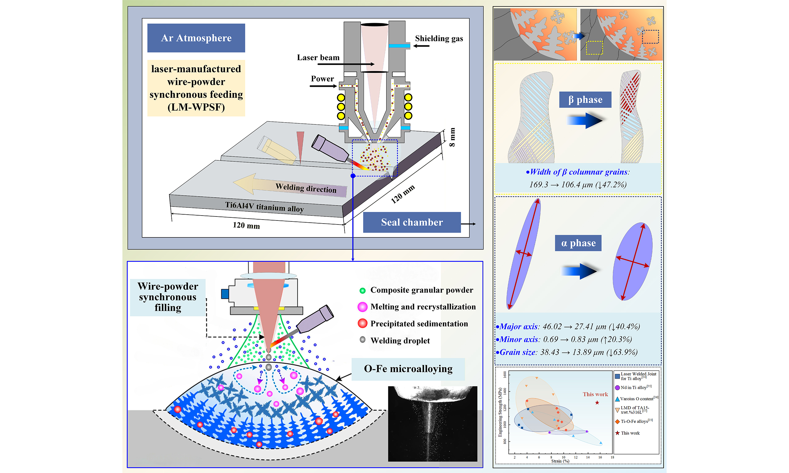
This study overcomes the long-standing strength-ductility trade-off in titanium alloy welding and additive manufacturing by introducing a novel laser-manufactured wire-powder synchronous feeding strategy incorporating oxygen-iron (O-Fe) microalloying. Through controlled experiments and multiscale characterization, the mechanism by which trace O-Fe additions regulate weld microstructure and mechanical properties is elucidated. The results show that O-Fe microalloying particles modify the growth conditions of acicular α/α′, reducing its aspect ratio and alleviating stress concentration at α/β phase boundaries. The microalloying elements substantially refine the grains during solidification through solute redistribution and a pronounced increase in undercooling. Quantitative analyses demonstrate that O-Fe microalloying reduces columnar grain width by 64.8%, modifies the aspect ratio of acicular α/α′ through solute redistribution with a 20.3% increase in minor axis and a 40.4% decrease in major axis, and achieves 63.9% grain refinement through elevated α/β interfacial energy and promoted heterogeneous nucleation. The optimized Ti-6Al-4V-0.5O-2.3Fe alloy exhibits exceptional mechanical performance, with a tensile strength of 1,266.6 MPa representing a 41.3% improvement and an elongation of 15.5% indicating an 80.2% enhancement, demonstrating great potential for high-performance industrial applications.
Keywords
INTRODUCTION
Ti6Al4V titanium alloys are prized for their exceptional properties, including low density, high specific strength, and excellent resistance to high temperatures and corrosion, rendering them indispensable in aerospace applications[1,2]. In the welding of medium-thick titanium alloy plates, the combined effects of multi-pass thermal cycling and high-energy-density heat input result in the formation of coarse columnar grains that epitaxially grow across the interlayer remelting zone along the build direction[3]. These excessively large columnar grains severely deteriorate the material's ductility[4-6]. Meanwhile, the rapid melting and solidification process within the molten pool inevitably leads to the formation of acicular α' martensite with high aspect ratios, significantly increasing the weld's susceptibility to brittleness and hardening[7,8]. Additionally, localized stress concentration at the α/β interfaces leads to the preferential initiation of microcracks under plastic deformation, resulting in a pronounced inverse strength-ductility relationship in the material[9-11].
To achieve synergistic enhancement of strength and ductility in thick-section titanium alloy structures, current strategies include multi-parameter process optimization[12], multi-component alloy design[13], auxiliary energy field assistance[14] (e.g., ultrasonic or magnetic fields), and novel heat source development[15]. Among these techniques, composition modification through multi-element alloying has demonstrated particular effectiveness for mechanical property enhancement.
For the strengthening design of biphasic titanium alloys, the selection of alloying elements must account for their phase-stabilizing effects. α-β biphasic alloys are typically produced by incorporating α- and β-stabilizers into pure Ti. α-Stabilizers are limited to Al, N, O, C, Ga, and Ge[16,17], with N and C being impurities requiring strict control[18], while Ga and Ge are economically impractical for widespread use[19]. The trace element O, however, is an optimal α-phase strengthener, exhibiting ~20 times greater strengthening stability than Al[20,21]. Fu et al.[22] confirmed that controlled O doping (0.66 wt.%) in Ti-8Nb-2Fe alloys enhances mechanical properties via microstructural engineering. In contrast, β-phase stabilizers offer broader options, with Fe being the most effective and cost-efficient[23]. As the second-lightest β-stabilizer, Fe has enabled the development of additive-manufactured alloys like Ti-6Al-1.2Fe[24] and Ti-3Fe[25], providing cost-effective alternatives to Ti-6Al-4V with improved strength under optimized processing. Fe’s exceptional diffusivity (103~105 higher than Ti self-diffusion) accelerates dislocation climb[26], yet excessive Fe promotes coarse columnar grains, restricting its content in commercial alloys (e.g., ATI 425, Ti-10V-2Fe-3Al) to ~2 wt.%.
Current research on titanium alloy wire welding[27] remains constrained by the limited compositional variability of commercial filler wires and poor control over weld metal chemistry[28], leading most studies to focus exclusively on the individual effects of α- or β-stabilizers while neglecting elemental transport mechanisms and epitaxial growth phenomena under high-constraint welding conditions. Furthermore, the single-pass laser wire-feed welding process exhibits poor in-situ controllability over microstructural evolution[29]. To overcome these limitations, we developed a laser-manufactured wire-powder synchronous feeding (LM-WPSF) strategy that enables precise multi-element microalloying of Ti-6Al-4V welds with O-Fe. The LM-WPSF combines the advantages of high material utilization and processing efficiency from wire feeding with the compositional flexibility and superior comprehensive properties of powder feeding[30,31]. By simultaneously introducing both powder and wire into the molten pool, this approach reduces production costs, enhances deposition efficiency, and enables in-situ synthesis and precise control of microstructures and compositions[32].
This study presents a novel LM-WPSF strategy, incorporating O-Fe microalloying, is developed to achieve enhanced strength-ductility synergy in Ti-6Al-4V alloys. By wire-powder synchronizing feeding to enable in situ microstructure control within the molten pool, we systematically elucidate the influence of O-Fe additions on α-β phase transformation kinetics and precipitate morphology. The resultant modulation of solute partitioning offers a promising solution for high-performance laser welding of thick titanium structures.
EXPERIMENTAL
Equipment and materials
Ti-6Al-4V titanium alloy with dimensions of 100 mm × 100 mm × 8 mm (supplied by Baoji Yingdatai New Material Co., Ltd., Baoji, China) was utilized for LM-WPSF as depicted in Figure 1A. The experimental setup consisted of a fiber laser (RFL-C6000H, Raycus Fiber Laser Technologies Co., Ltd., Wuhan, China), a wire feeder (SSJ-10, Huihe Technology Co., Ltd., Wuhan, China), a powder feeder (HR-PFNM, Huirui Optoelectronics Technology Co., Ltd., Nanjing, China), a three-channel cladding head (TL310, Tongli Laser Technology Co., Ltd., Shanghai, China), and a 6-axis robot (KR30, KUKA, Augsburg, Germany). In this study, the LM-WPSF process was successfully implemented to join 8-mm-thick Ti-6Al-4V plates, achieving full penetration through six-layer filler metal deposition. The groove configuration of the substrate to be welded was shown in Figure 1B. In this welding process, the wire and powder were simultaneously fed into the molten pool, the workpiece to be welded was in a sealed box under Ar gas environment. The wire-powder synchronization device was fixed on the laser head and moved synchronously with the laser head. The relative position of the laser head was set by the KUKA robot.
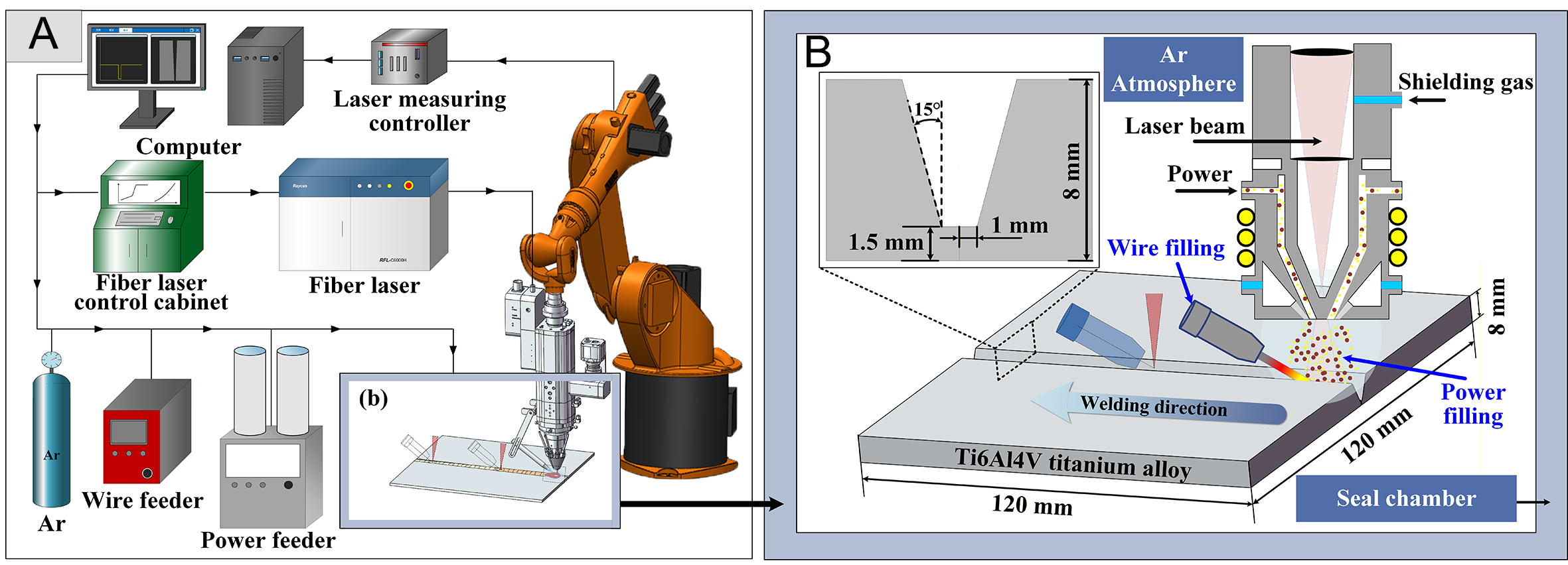
Figure 1. Laser-manufactured wire-powder synchronous feeding platform: (A) Experimental facilities; (B) Schematic diagram of LM-WPSF.
In the present study, a welding wire with a diameter of 1.2 mm (supplied by Baoti Group Co., Ltd., Baoji, China) was employed. The detailed chemical compositions of both the base metal and the welding wire are listed in Table 1. The O-Fe microalloyed titanium composite powder was prepared by mechanically mixing Ti-6Al-4V powder with TiO2 and Fe powders (supplied by Beijing Ryubon New Material Technology Co., Ltd., Beijing, China) at a weight ratio of 85:5:10. The particle morphology, particle size distribution, and XRD patterns of the constituent powders are presented in Figure 2. The Ti-6Al-4V and Fe powders exhibit predominantly spherical morphologies, with average particle diameters of 113.57 and 105.6 μm, respectively. In contrast, the TiO2 powder shows an irregular morphology with a nanoscale average particle size of approximately 79.8 nm. The composite powder was synthesized by planetary ball (XQM-4, Changsha Tianchuang Powder Technology Co., Ltd., Changsha, China) milling at 300 rpm for 6 h to ensure uniform dispersion of the alloying components. After milling, the powder demonstrated good flowability, with a measured flow time of 22.1 s per 50 g. Notably, the nanoscale TiO2 particles were uniformly distributed and adhered to the surfaces of the Ti-6Al-4V and Fe powders, indicating effective mechanical mixing. Prior to welding, the powder mixture was dried in a vacuum drying oven (DZF series, Shanghai Binglin Electronic Technology Co., Ltd., Shanghai, China) for 6 h to remove residual moisture and to ensure stable and consistent powder feeding during the wire-powder synchronous feeding process.
Chemical composition and mechanical properties of base metal
| Element (wt%) | Ti | Al | V | Fe | C | O | H |
| Base metal | Bal. | 6.17 | 4.04 | 0.13 | 0.01 | 0.088 | 0.004 |
| Welding wire | Bal. | 5.75 | 3.82 | 0.04 | 0.012 | 0.08 | 0.001 |
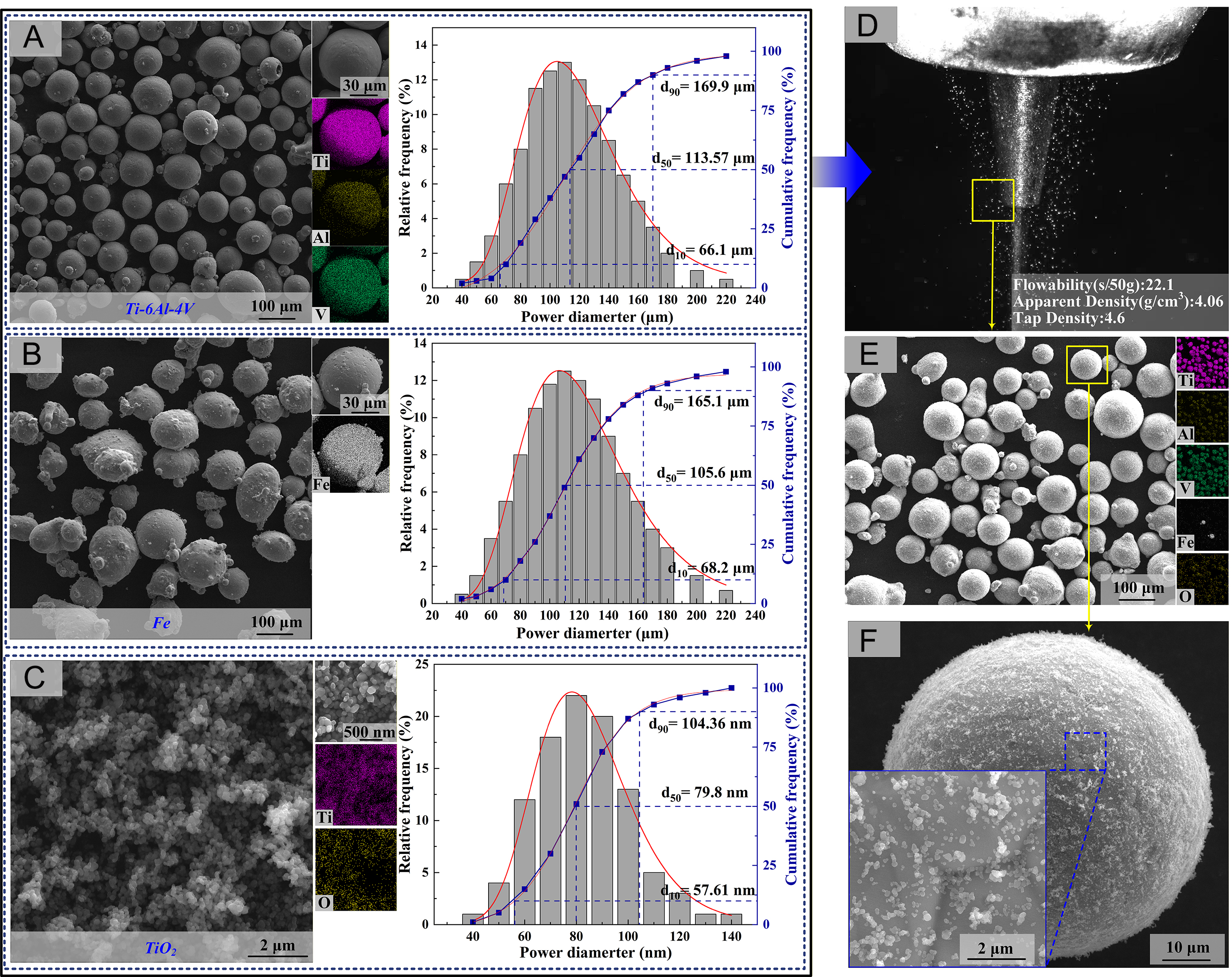
Figure 2. Morphology, particle size distribution, and physical characteristics of the powders and wire-powder feeding process: (A-C) SEM images, corresponding EDS elemental maps, and particle size distributions of Ti-6Al-4V, Fe, and TiO2 powders, respectively.(D) In-situ photograph of the wire–powder synchronous feeding process in the LM-WPSF system. (E) SEM morphology of the O-Fe microalloyed Ti-based composite powder. (F) High-resolution SEM image showing detailed surface features and nanoparticle decoration on the powder particles.
Furthermore, the roles of the alloying components are clarified as follows: TiO2 acts as an oxygen carrier, supplying a controlled source of dissolved oxygen; dissolved oxygen functions as an interstitial strengthening element and influences microstructural evolution; and Fe serves as a β-stabilizing element, affecting phase stability and solute redistribution during welding, solidification, and subsequent deformation.
The elemental composition of the weld seams under different process parameters was determined by electron probe microanalysis (EPMA). It should be noted that, although EPMA provides reliable quantitative analysis for metallic elements, the measurement of oxygen is subject to higher uncertainty due to its low atomic number. Therefore, the reported oxygen values are used primarily for comparative analysis rather than absolute quantification. Additional details of the experimental setup for LM-WPSF are summarized in Table 2.
Main welding process parameters
| Pattern number | Weld composition | Laser welding mode | Laser power | Welding speed | Defocus | Wire feed speed | Powder feed rate |
| #1 | Ti6Al4V | Wire filling | 3,500 W | 20 mm/s | +5 mm | 35 mm/s | \ |
| #2 | Ti6Al4V-0.5O-2.3Fe | Wire-powder synchronous filling | 1.0 rpm/min (3.2 g/min) | ||||
| #3 | Ti6Al4V-0.54O-3.7Fe | 1.5 rpm/min (4.8 g/min) |
Microstructure characterization and mechanical properties analysis
The specimens intended for optical microscopy (OM, LEICA DM4000 microscope, Leica Microsystems, Wetzlar, Germany) and scanning electron microscopy (SEM, TESCAN, Brno, Czech Republic) analysis were sectioned perpendicular to the welding direction. These samples, measuring 10 mm × 10 mm × 8 mm, were polished using Kroll reagent (2%HF + 10%HNO3 + 88%H2O) before examination in SEM utilizing TESCAN LYRA3 dual beam focused ion beam SEM that was equipped with EDS. Using Image-Pro software to analyze grain morphology (by manually identifying fully bounded columnar grains and measuring their average short-axis length). The specific measurement procedure consisted of: (1) collecting multiple SEM images with clearly visible phase boundary morphology from different sample regions, and (2) measuring ≥ 100 phase dimensions per weld zone using ImageJ software to ensure measurement accuracy. The distributions of elements Al, V, Fe and O were detected using Electron Probe X-ray Microanalysis (EPMA, JXA-8230, JEOL Ltd., Tokyo, Japan). Phase analysis was carried out using X-ray diffraction (XRD, SmartLab, Rigaku Corporation, Tokyo, Japan). A Cu-Kα radiation source with an accelerating voltage of 40 kV and a current of 250 mA was applied, and Jade 6.0 software was used to analyze the XRD patterns. Electron back scattering diffraction (EBSD, Hitachi S-4800, Tokyo, Japan) was used to investigate texture characteristics, grain orientation, and misorientation angle in the vicinity of the weld center before and after the O-Fe reinforcement element was added by the LM-WPSF. Transmission electron microscope (TEM, FEI Talos F200X G2, Hillsboro, OR, USA) was employed at high magnification to analyze the microstructural modifications and dimensional alterations in welds subjected to O-Fe microalloying strengthening. Realtime temperature monitoring during the welding process was carried out with a V916GHT infrared thermal imager (Vidolis Technology Co., Ltd., Shenzhen, China), which offers a measurement accuracy of ±2% or
Tensile specimens were machined from the weld metal (fusion zone) of the modified alloys to evaluate the intrinsic mechanical properties of the microalloyed region. The gauge section was carefully extracted entirely from the chemically and microstructurally homogeneous fusion zone. This ensures that the reported tensile properties are representative of the O-Fe microalloyed weld metal itself, without influence from the base material or heat-affected zone. Quasi-static tensile tests were performed at a crosshead speed of 1 mm/min using a CMT-5105 (MTS Systems (China) Co., Ltd., Shenzhen, China) testing machine. Both transverse-weld specimens (containing base metal) and longitudinal specimens (pure weld metal) were prepared according to GB/T 2651-2008, with dimensions shown in Figure 3.
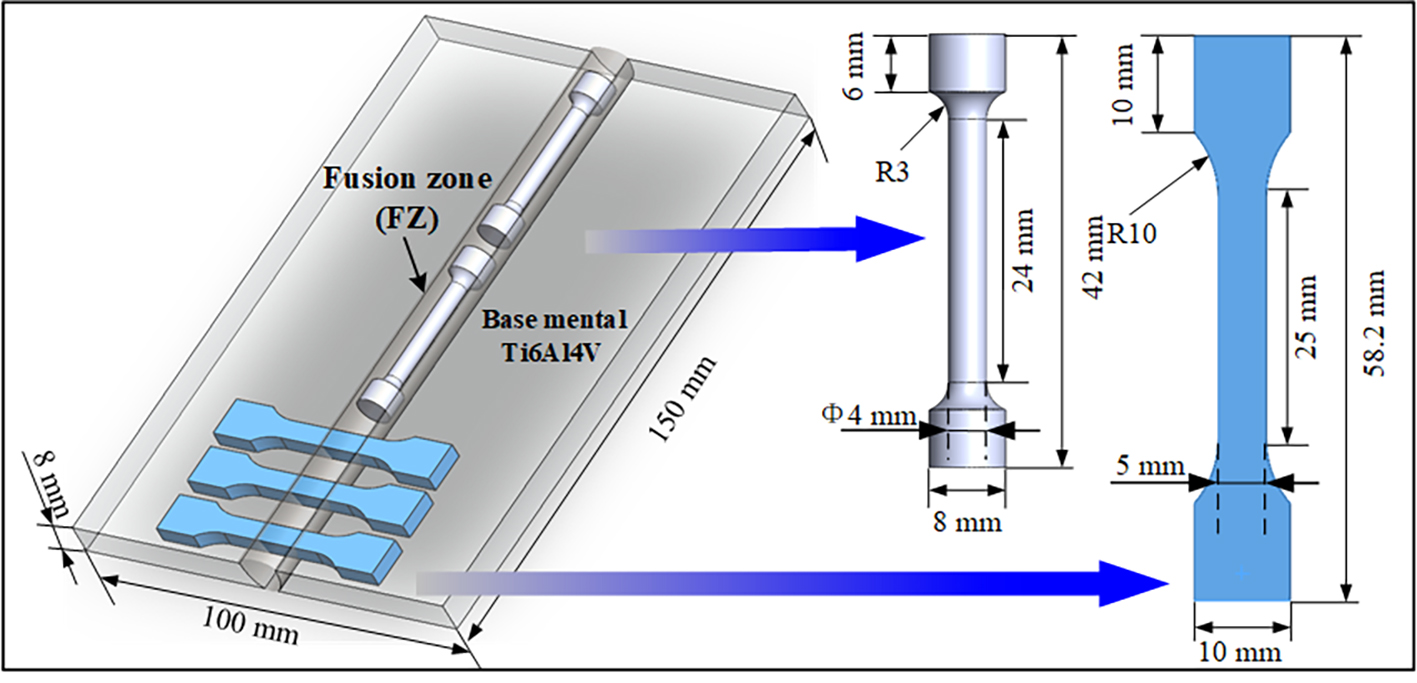
Figure 3. Dimension of quasi-static tensile specimen (mm).
RESULTS AND DISCUSSION
Effect of O-Fe strengthening elements on the microstructure
The microstructure of LM-WPSF welded joints under varying parameters is presented in Figure 4. As illustrated in Figure 4(A1-A3), the as-welded Ti-6Al-4V (without microalloying) is characterized by coarse columnar grains that epitaxially grow from the fusion boundary at the weld root, traversing interlayer fusion lines with pronounced directional solidification behavior. Wang et al.[33] demonstrated that coarse columnar grain structures oriented along the deposition direction significantly degrade the component's overall mechanical performance, particularly reducing ductility in directions perpendicular to the grain growth orientation. To refine the microstructure, a minor quantity of O-Fe stabilizing alloying elements was introduced during welding. In contrast to the non-microalloyed Ti-6Al-4V weld, Figure 4(B1-C3) illustrates the morphological evolution in the central weld metal region under wire-powder synchronous feeding with different O-Fe microalloying additions (namely Ti-6Al-4V-0.5O-2.3Fe and Ti-6Al-4V-0.54O-3.7Fe). Notably, the weld metal density exhibited a slight increase from 4.43 to 4.47 g/cm3 with O-Fe microalloying, which can be attributed to the presence of precipitated phase. This minor variation does not compromise the lightweight advantage of titanium structures.
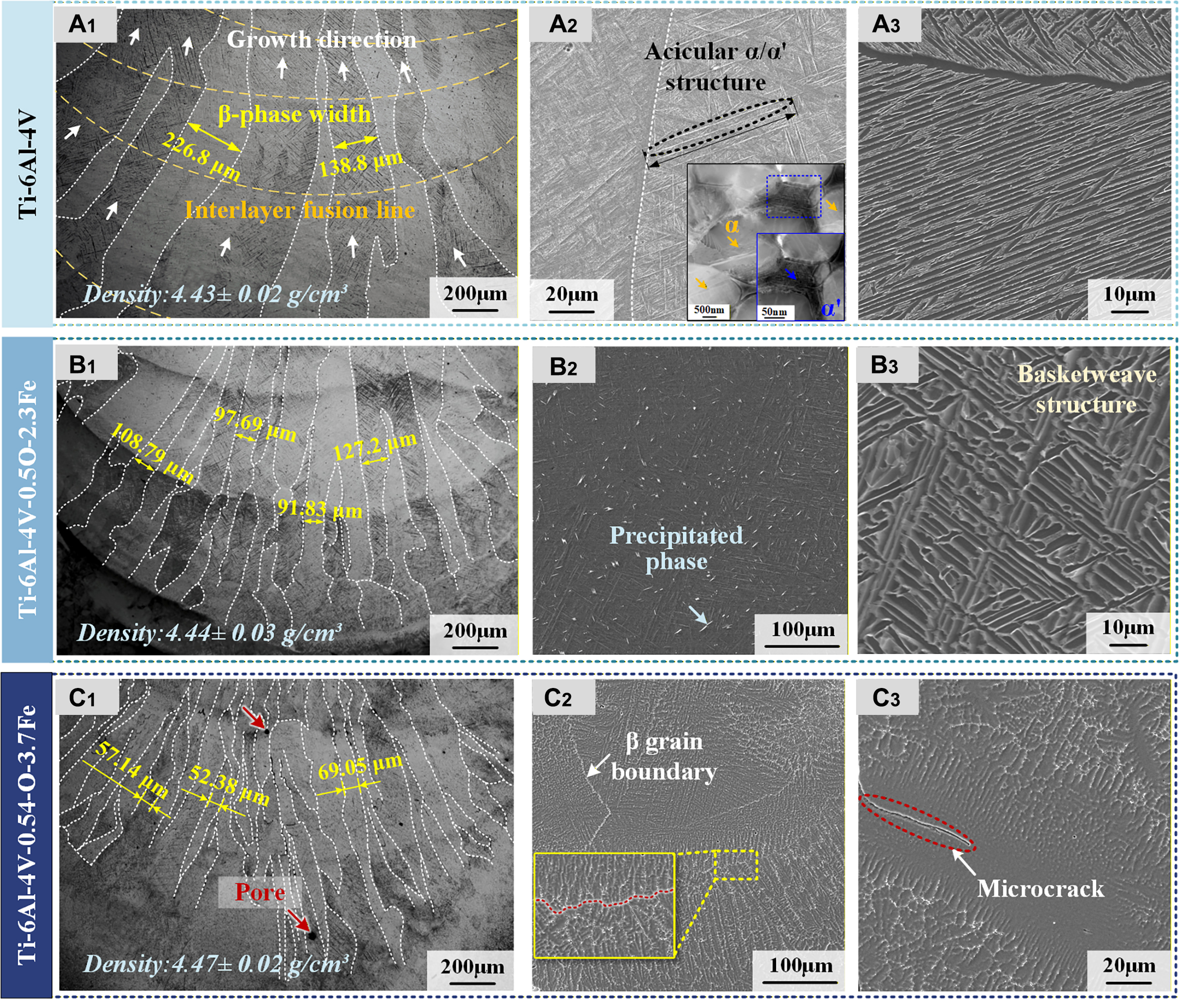
Figure 4. Microstructure of laser welded joint under different element composition: (A1) Base Ti-6Al-4V with corresponding (A2 and A3) high-magnification SEM and TEM; (B1) Ti-6Al-4V-0.5O-2.3Fe with corresponding (B2 and B3) high-magnification SEM; (C1) Ti-6Al-4V-0.54O-3.7Fe with corresponding (C2 and C3) high-magnification SEM.
Using Image-Pro software to quantify grain morphology, the width of primary β columnar grains decreased markedly with increasing additions of strengthening elements. The unalloyed Ti-6Al-4V weld (no O-Fe additions) exhibited primary β columnar grains with an average width of 169.3 μm. With the addition of O-Fe, the columnar grain width was reduced: for Ti-6Al-4V-0.5O-2.3Fe the average primary β columnar width decreased to 106.4 μm (a reduction of ≈ 37.2% relative to Ti-6Al-4V), and for Ti-6Al-4V-0.54O-3.7Fe it was further reduced to 59.53 μm (a reduction of ≈ 64.8% relative to Ti-6Al-4V). These results demonstrate that O-Fe alloying strongly inhibits columnar grain growth and produces significant refinement in the β columnar grain width.
To clarify the phase composition of these acicular features, TEM analysis is provided in Figure 4A2. The results clearly reveal the presence of both equilibrium α phase and secondary-precipitated martensitic α′ within the prior β matrix[34]. Consequently, in SEM-based analysis, these acicular features are conservatively termed α/α′-type structures unless TEM morphological evidence supports further distinction.
SEM characterization reveals a progressive morphological evolution of fine acicular α structures with increasing O-Fe content. In pure Ti-6Al-4V welds [Figure 4(A2 and A3)], acicular α/α′ structures preferentially nucleated and grew along the coarse prior-β grain boundaries, with individual needles reaching lengths of up to 46.02 μm. For the Ti-6Al-4V-0.5O-2.3Fe composition [Figure 4(B2 and B3)], the acicular α/α′-like structures exhibit reduced lengths, with an average value of 27.41 μm. In this condition, the secondary α phase forms finer lamellae with lower aspect ratios, resulting in an interlaced basket-weave-like morphology.
With a further increase in O-Fe content to Ti-6Al-4V-0.54O-3.7Fe, pronounced modifications in the morphology of secondary acicular α-based structures are observed. As shown in Figure 4C2, the interfaces between adjacent acicular features evolve from relatively continuous to more discontinuous configurations, indicating an increased degree of segmentation and refinement. This morphological evolution is associated with changes in the growth characteristics of the acicular α/α′-type laths.
At higher Fe contents, the weld exhibits signs of reduced microstructural integrity. High-magnification SEM observations [Figure 4C3] reveal the presence of localized microcracks and porosity within the weld seam, indicating that excessive Fe addition under the present powder-filling parameters may lead to material embrittlement. The increased number of pores in Figure 4C1 after O-Fe microalloying can be attributed to several factors. The higher oxygen content raises melt viscosity and reduces fluidity, hindering gas escape during solidification[35]. Fe addition may also alter the solidification pathway and promote microsegregation, facilitating pore retention. Moreover, partial decomposition of TiO2 during laser welding can release oxygen gas that becomes trapped in the rapidly solidifying melt pool.
The dimensions of the plate-shaped α phase were analyzed and measured, with the results shown in Figure 5. Under the influence of O-Fe microalloying elements, the aspect ratio of the strip-shaped α phase decreased. Its major axis size decreased from 46.02-27.41 μm, representing a 40.4% decrease. Furthermore, the short-axis width variation was measured using the same method under high-magnification SEM. As shown in Figure 5C, the average width increased from 0.69-0.83 μm, corresponding to a 20.3% increase.
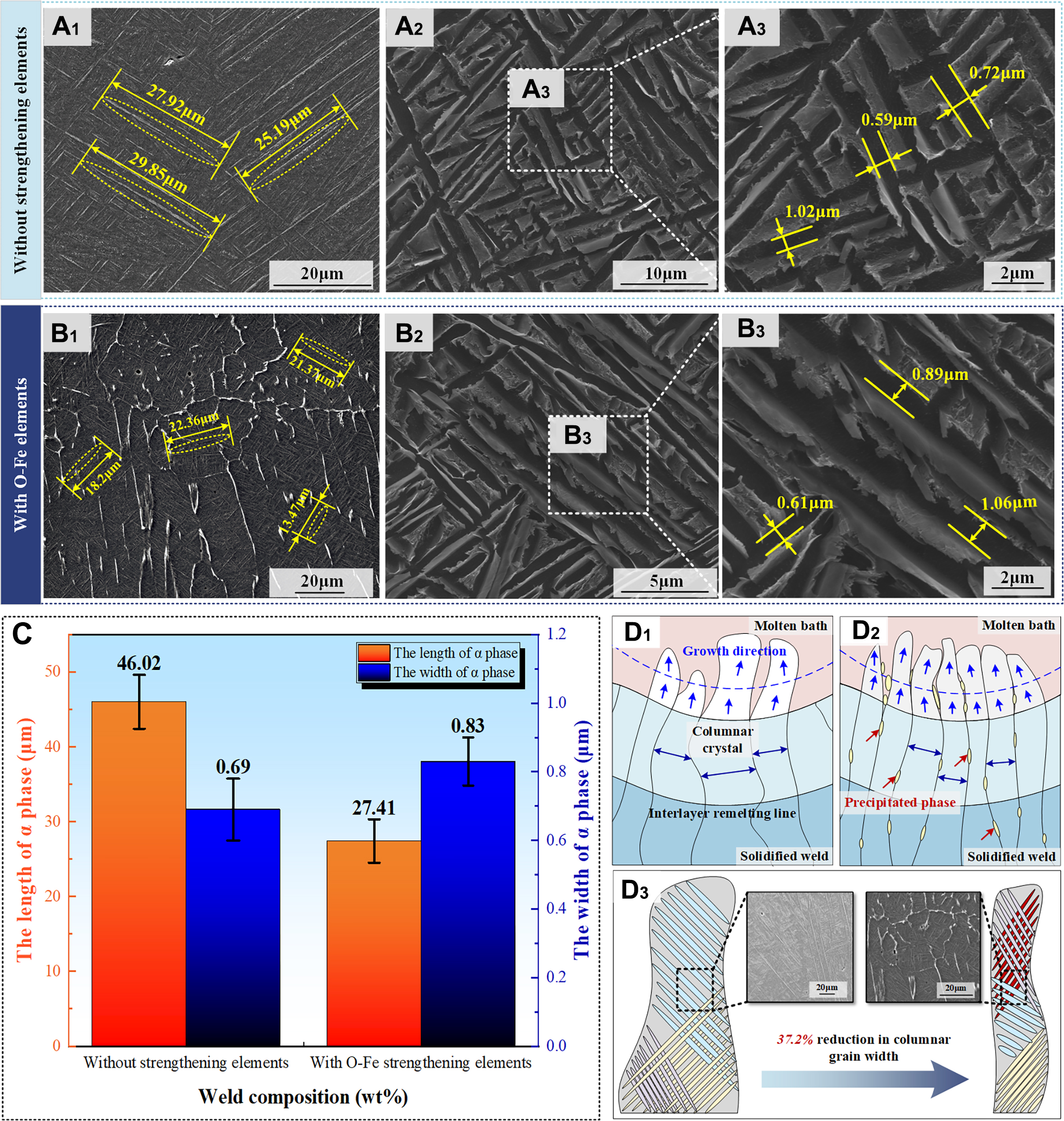
Figure 5. Microstructural evolution of α-phase under O-Fe microalloying: (A1-A3) SEM morphology of Ti-6Al-4V welded joint; (B1-B3) SEM morphology of Ti-6Al-4V-0.5O-2.3Fe welded joint; (C) Statistical results of the long and short diameters of the plate α phase; (D1-D3) Schematic diagrams of the growth process of columnar crystals with and without O-Fe element strengthening. Error bars represent the standard deviation (n ≥ 100 phase dimensions measured per weld zone).
The refinement of the plate-like α phase is governed by its geometric relationship with the width of the β columnar grains. O-Fe microalloying promotes heterogeneous precipitation along β columnar grain boundaries [Figure 5(B1 and D2)], effectively suppressing β-grain coarsening and resulting in a 37.2% reduction in columnar grain width. In α-β titanium alloys, solidification proceeds through β formation from the melt, followed by the β→α transformation during cooling. As the temperature decreases, the α phase nucleates within the β matrix, initiating at β grain boundaries and growing inward. Its growth kinetics are therefore geometrically constrained by the width of the β columnar grains [Figure 5D3].
Under the influence of the strengthening elements, the aspect ratio of the lath-shaped α grains was significantly reduced. This microstructural modification contributed to a decrease in stress concentration sites[36,37], thereby inhibiting the initiation of microcracks. This improvement enables the material to endure higher stresses during tensile loading while mitigating brittle fracture tendencies. Furthermore, the reduced aspect ratio of acicular structures promotes microstructural homogenization, leading to more uniform deformation behavior under tensile stress. This microstructural evolution effectively prevents localized premature plastic instability while enhancing mechanical performance. Compared to plate-like and lamellar microstructures, the spheroidized structure demonstrates a superior balance between strength and ductility.
Element distribution and phase composition
To investigate the influence mechanism of O-Fe strengthening elements on weld microstructure transformation, the elemental distribution in LM-WPSF welded joints was characterized using EPMA. The phase composition was subsequently identified by XRD analysis. As shown in Figure 6, distinct microstructural differences were observed between conventional and modified welds.
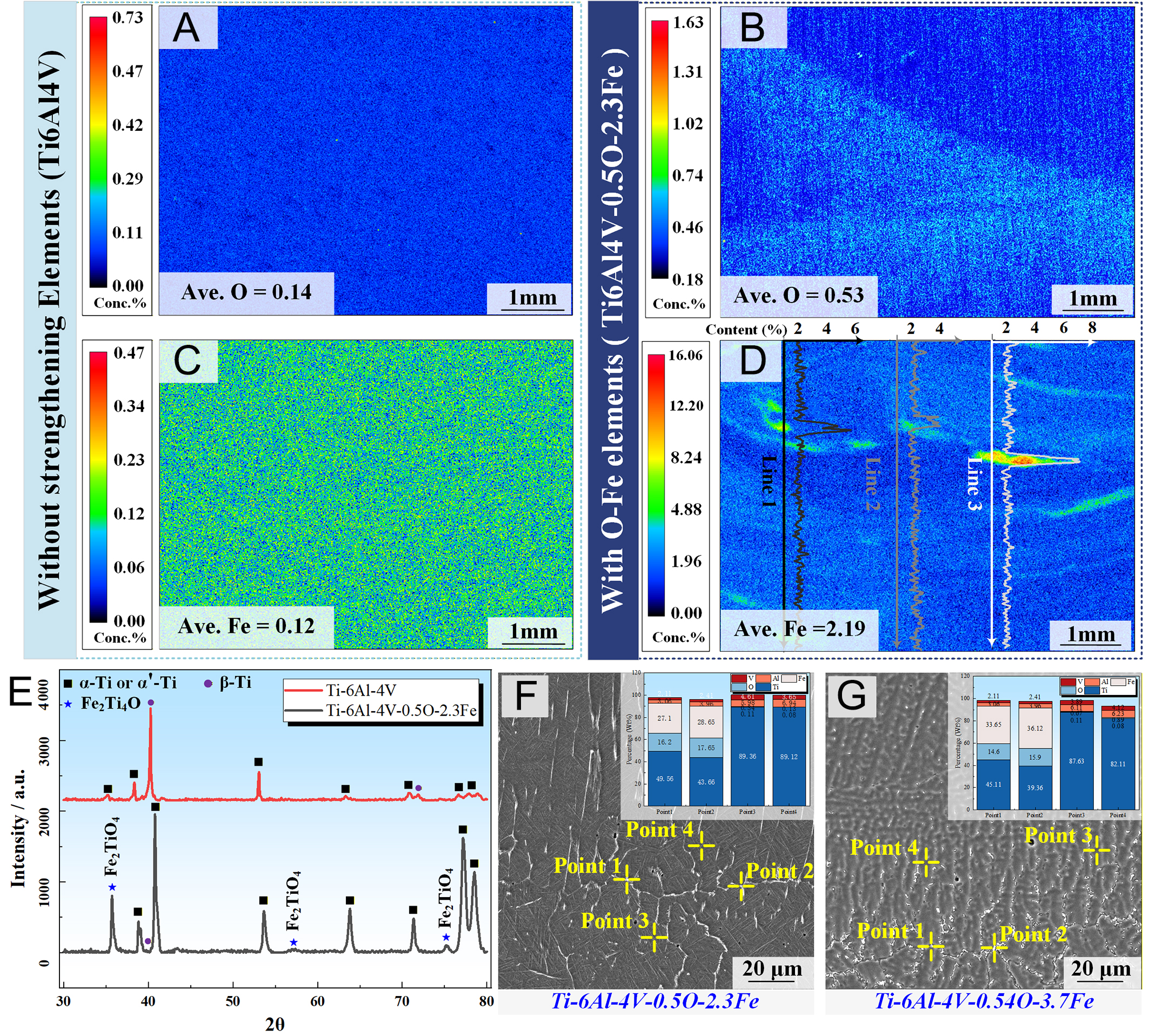
Figure 6. Microstructural characterization of welds with and without O-Fe microalloying: (A and B) EPMA elemental mapping of conventional Ti-6Al-4V weld; (C and D) EPMA analysis of O-Fe modified weld; (E) Comparative XRD patterns of Ti-6Al-4V and Ti6Al4V-0.5O-2.3Fe welds; (F and G) SEM micrograph showing Fe2Ti4O precipitates in Ti6Al4V-0.5O-2.3Fe and Ti6Al4V-0.54O-3.7Fe weld.
In the weld without strengthening additives, EPMA mapping revealed homogeneous distributions of Fe and O throughout the weld as shown in Figures 5B and 6A, consistent with the identical composition of the filler wire and base material (Ti-6Al-4V). In contrast, the distribution of O and Fe elements in the Ti-6Al-4V-0.5O-2.3Fe weld exhibits substantial differences. During LM-WPSF, the microalloying particles (in powder form) and the welding wire were co-delivered into the molten pool and subsequently melted. As shown in Figure 6C and D, the Fe content increases substantially from 0.12-2.19 wt.% (Δ2.07 wt.%), while the O content shows a more moderate increase from 0.14-0.53 wt.% (Δ0.39 wt.%), consistent with its approximate 0.6 wt.% solubility limit in this system.
Despite the predominant dissolution of microalloying elements into the molten pool, residual interlayer segregation remained an unavoidable phenomenon.EPMA analysis in Figure 6D reveals localized precipitation phase aggregation in interlayer remelting zones of the trace-element-modified weld. Line-scan analyses of Fe along different trajectories reveal pronounced Fe segregation at the interlayer regions. A sharp and isolated enrichment peak is consistently observed at the interlayer position, with peak Fe contents ranging from 3.4% to 6.8%. Consistently, EPMA elemental mapping confirms that the maximum Fe concentration is also localized at the interlayer accumulation region, where the peak value reaches approximately 16%, which is significantly higher than that within the intralayer regions. In contrast, the average Fe content inside the layers remains relatively uniform, at approximately 2.11%. Among the examined line scans, Line 3 exhibits the most severe interlayer segregation, indicating a higher degree of local Fe enrichment. Such micro-scale compositional inhomogeneity is an inherent challenge associated with in-situ alloying processes, highlighting the difficulty in achieving uniform elemental distribution at the microscale. The enrichment is confined to narrow interlayer regions with a characteristic width on the order of several micrometers, as evidenced by the sharp and localized peaks in the line-scan profiles. Such segregation is therefore highly localized rather than pervasive throughout the bulk.
To identify the phase composition in these regions, EDS point analysis and XRD characterization were performed at the interlayer remelting zones. Figure 6E presents comparative XRD patterns of Ti-6Al-4V and Ti6Al4V-0.5O-2.3Fe welded joints. The O-Fe modified joint demonstrates significantly different phase distribution characteristics, as evidenced by the relative peak intensities in the XRD pattern. The unmodified joint exhibits characteristic phases including hexagonal-close-packed (hcp) α-phase, martensitic α'-phase, body-centered cubic (bcc) β-phase. The Ti6Al4V-0.5O-2.3Fe alloy exhibits enhanced diffraction peak intensities for both hcp α-phase and α'-phase, along with distinct characteristic peaks corresponding to the Fe2Ti4O intermetallic phase.
To further analyze the morphology of precipitates, the O-Fe micro-alloyed precipitates in different compositions were observed, as shown in Figure 6F and G. EDS point scanning was performed on the white precipitates, revealing that these phases contain higher Fe and O concentrations compared to other regions. It should be noted that EDS is not suitable for accurate quantification of oxygen due to its limited sensitivity to light elements and matrix absorption effects. These precipitates preferentially segregated at grain boundaries, effectively interrupting and refining the coarse original columnar grains. This grain refinement is corroborated by the decreased columnar grain sizes presented in Figure 4(A1, B1, C1).
With a further increase in O-Fe content, as illustrated in Figure 6G, the grain boundaries exhibited a more discontinuous morphology, and localized porosity defects were observed. Comparing the SEM micrographs in Figure 4(C2 and B2), an excessive Fe content led to a "vein-like" network of precipitates along the grain boundaries. This morphology is attributed to the pronounced segregation tendency of Fe, which diffuses rapidly in titanium (103-105 times faster than Ti self-diffusion) and tends to accumulate at grain and phase boundaries[19,35]. An excessive amount of such intergranular precipitates can reduce grain boundary cohesion, promote intergranular fracture, increase susceptibility to solidification cracking, and ultimately degrade ductility.
Grain morphology analysis and crystallographic orientation
The EPMA elemental mapping in Figure 6 reveals distinct agglomeration and microsegregation of O-Fe trace elements at interlayer fusion zones. This localized elemental accumulation induces significant microstructural modifications, including altered growth kinetics of columnar grains and refined grain size distribution. Based on this microstructural characterization, EBSD analysis was performed to quantitatively evaluate grain morphology, size distribution, and grain boundary misorientation angles [Figure 7]. In the pure Ti-6Al-4V weld, epitaxial growth of columnar β grains occurs across multiple deposition layers, with the grain structure extending continuously through the fusion boundary regions [Figure 7A1]. These coarse columnar grains exhibit preferential growth orientation along the build direction, nucleating from the weld centerline and propagating vertically upward, consistent with previous reports of titanium alloy solidification behavior[38].
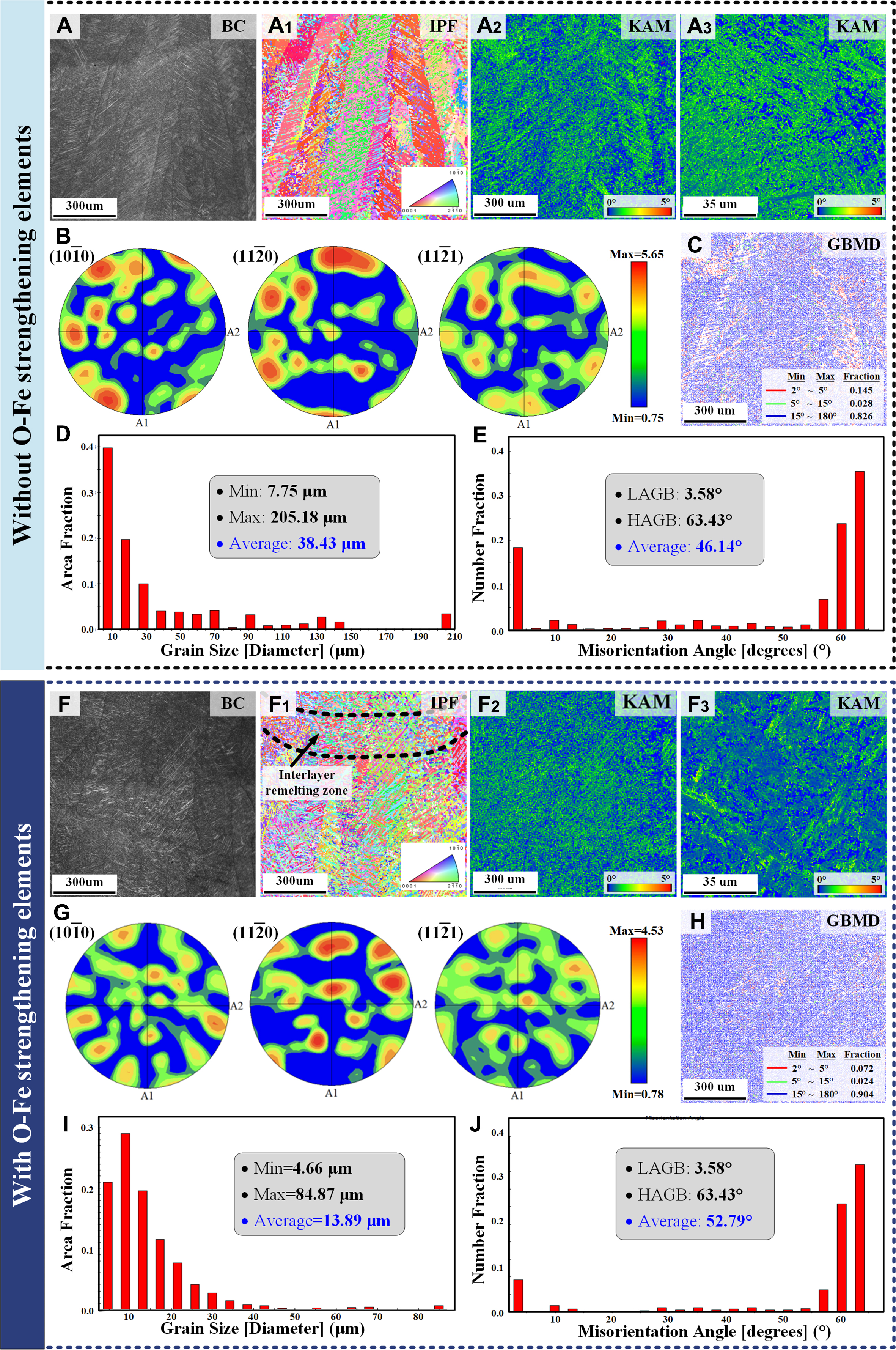
Figure 7. EBSD analysis of LM-WPSF Ti-6Al-4V (A–E) and Ti-6Al-4V-0.5O-2.3Fe (F–J) alloys: (A) Band contrast (BC) map of the unmodified alloy, (A1) Inverse pole figure (IPF) map, (A2 and A3) Kernel average misorientation (KAM) maps, (B) Pole figures of the α phase, (C) Grain boundary misorientation distribution (GBMD), (D) Grain size distribution, (E) Misorientation angle distribution; (F–J) Corresponding EBSD maps and analyses for the O-Fe microalloyed alloy: (F) BC map, (F1) IPF map, (F2 and F3) KAM maps, (G) Pole figures of the α phase, (H) GBMD, (I) Grain size distribution, (J) Misorientation angle distribution.
The addition of O-Fe microalloying elements significantly refines the columnar grain structure, particularly in interlayer remelting zones [Figure 7F1], the microstructure transitions from a predominantly lamellar morphology to a more disordered, basketweave arrangement of α phases. Quantitative analysis of grain size distributions before and after O-Fe microalloying reveals substantial refinement [Figure 7D and E]. The average α-phase grain diameter decreased markedly from 38.43 ± 2.17 μm to 13.89 ± 0.92 μm, representing a 63.9% reduction in grain size.
Figure 7(A2 and A3, F2 and F3) present the kernel average misorientation (KAM) maps for welds with and without O-Fe microalloying. In the unmodified weld, dislocations exhibit locally high yet non-uniform density distribution, with significant stress concentration predominantly occurring at α/β phase boundaries. This heterogeneous dislocation arrangement promotes strain localization during plastic deformation, ultimately deteriorating material ductility. Furthermore, within regions of relatively low dislocation density, limited dislocation interactions facilitate unrestricted dislocation glide, thereby reducing work hardening capability. The consequent stress intensification further compromises plastic deformation capacity. In contrast, the O-Fe modified weld seam [Figure 7(F2 and F3)] exhibits a refined lamellar microstructure with significantly more homogeneous dislocation density distribution. High-resolution characterization reveals substantially reduced dislocation density within individual β columnar crystal, suggesting effective dislocation annihilation during the phase transformation. The microalloying-induced grain refinement increases grain boundary density, which effectively restricts dislocation motion and elevates the material's tensile strength through boundary strengthening.
Figure 7B and G present the pole figures of the welds produced with and without O-Fe microalloying. Quantitative texture analysis indicates that the maximum pole density decreases from 5.65 to 4.53 after microalloying, corresponding to a reduction of approximately 19.8%, which reflects a noticeable weakening of crystallographic texture. In the microalloyed weld, the high-intensity regions in the pole figures become more dispersed, exhibiting a broader distribution rather than a strongly concentrated preferred orientation. This texture randomization suggests that, although the fundamental α/β crystallographic orientation relationship remains unchanged and continues to follow the Burgers orientation relationship, the subsequent growth and competitive selection of favorably oriented grains are effectively suppressed. During the LM-WPSF process, O-Fe microalloying modifies the local thermal and solutal conditions in the molten pool and solidification front, thereby restricting directional grain growth and reducing the dominance of specific crystallographic variants. As a result, grain morphology becomes more refined and the overall orientation distribution more uniform, leading to reduced texture intensity without altering the intrinsic α/β crystallographic relationship. From a macroscopic perspective, this texture weakening contributes to improved microstructural homogeneity and isotropy, which is beneficial for the comprehensive mechanical performance and long-term service stability of the alloy.
The deviations in grain boundary orientation angles were compared with and without the influence of strengthening elements. The grain boundaries were categorized into two types based on their misorientation angles: High-angle grain boundaries (HAGBs, > 15°) and Low-angle grain boundaries (LAGBs, ≤ 15°)[39]. In Figure 7C and H, high-angle grain boundaries are indicated by blue lines, whereas low-angle grain boundaries are denoted by green and red lines. Under the microalloying effect of O-Fe, the proportion of HAGBs increased from 82.6% to 90.4%, representing a 7.8% relative increase. This higher density of HAGBs improved the material’s resistance to dislocation motion. Statistical analysis of misorientation angles
TEM characterization of acicular α morphology
The microstructural morphologies at various locations within the welded joints—both with and without O-Fe microalloying—were characterized and compared using TEM. The results are presented in Figure 8, showing pronounced differences in microstructural characteristics and dislocation distributions between welds with and without O-Fe strengthening elements. In the unmodified weld, dislocations predominantly accumulate at α-phase grain boundaries, inducing localized stress concentrations. This correlates with the presence of discontinuous acicular α-phase particles exhibiting significant size variations. By contrast, O-Fe modified welds display a more homogeneous dislocation distribution with reduced density, tightly packed parallel α-phase arrangements, and localized basket-weave morphology, as shown in the Figure 8A3. These microstructural modifications confirm the effectiveness of O-Fe microalloying in enhancing weld homogeneity.
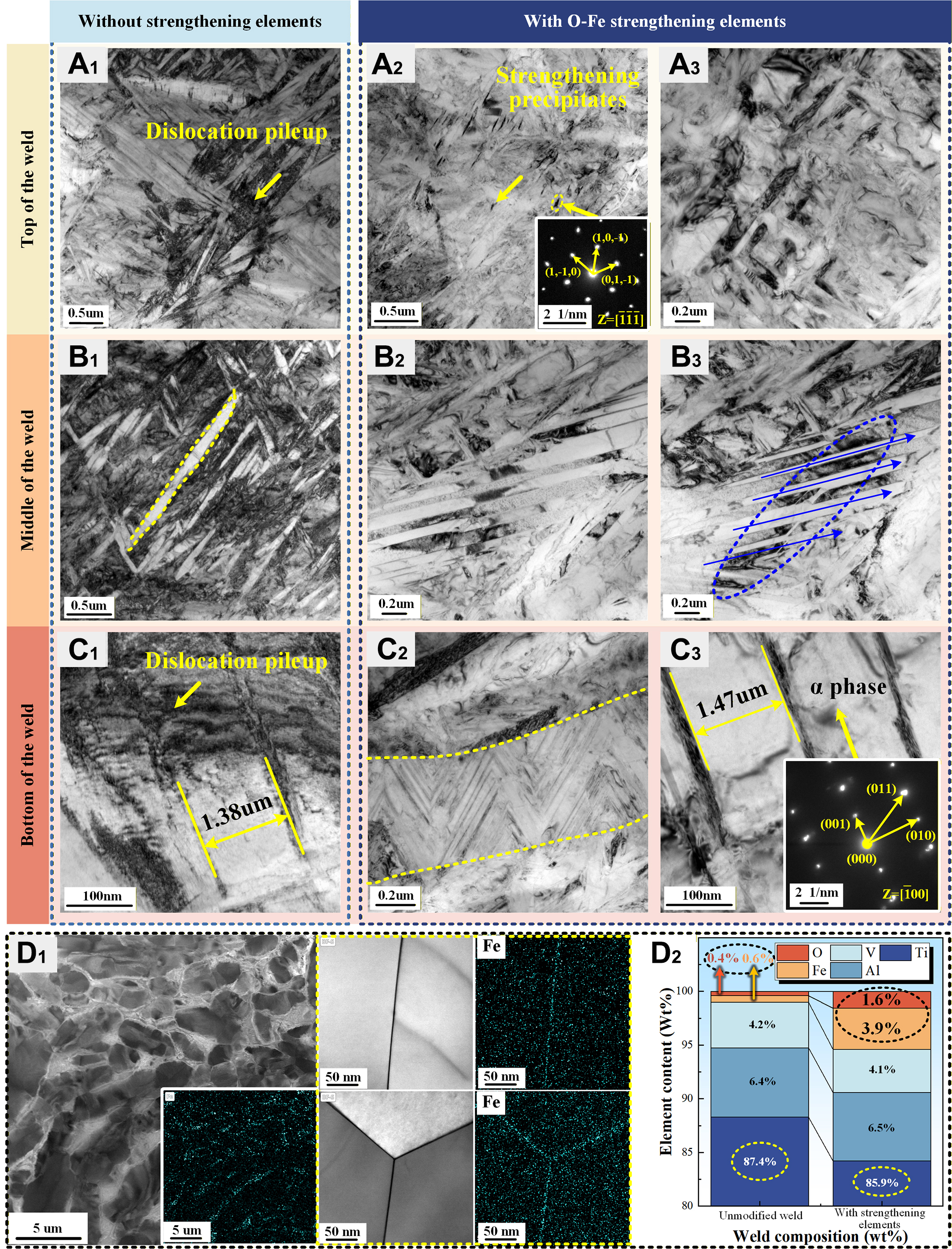
Figure 8. Comparative TEM analysis of microstructural evolution in conventional and O-Fe microalloyed Ti-6Al-4V weld seams: (A1-A3) Top of the weld; (B1-B3) Middle of the weld; (C1-C3) Bottom of the weld; (D1 and D2) Quantitative comparison of element redistribution and content in microalloyed welds.
Comparative analysis reveals distinct microstructural differences across weld regions. In the weld root, α-phase particles coarsen significantly (1.38-1.47 μm width) due to multi-pass thermal accumulation. TEM images highlight local fine scale features within α laths, whereas SEM provides statistical averages over larger microstructural volumes; both are consistent with the overall refinement trend. The unstrengthened weld exhibits obvious dislocation pile-ups distributed across lamellar α-phase, while the strengthened weld shows fewer dislocations with effective intragranular dislocation control. The weld center region exhibits significantly refined α-phase widths compared to the root zone. Notably, O-Fe microalloying promotes more uniform α-phase growth, with Figure 8B3 demonstrating how the lamellar α-phase morphology disrupts the original dislocation concentration pattern. This phenomenon mitigates stress accumulation, as α-phase interfaces effectively impede dislocation glide, thereby promoting homogeneous plastic deformation and suppressing premature microcrack initiation. In the weld top region, secondary precipitated phases (confirmed in Figure 8A2) appear as short, lens-shaped dark features. Crystallographic analysis shows that the Fe2Ti4O precipitates adopt a cubic structure with a lattice parameter of ~11.297 Å, which allows favorable lattice matching with the hexagonal α/α′ matrix in Ti-6Al-4V. The approximate lattice correspondence facilitates the formation of coherent or semi-coherent interfaces, consistent with the well-defined diffraction spots and fixed zone axis observed in the SAED patterns. This crystallographic relationship indicates that the precipitates are not randomly oriented and enables effective restriction of α/α′ lath growth by stabilizing phase boundaries and reducing interfacial mobility.
As shown in Figure 8D1, EDS mapping of the O-Fe microalloyed joint reveals pronounced segregation and accumulation of Fe along α-phase boundaries. This indicates that the added strengthening particles primarily enhance the material through a solidsolution mechanism. During solidification, Fe, as a strong β-stabilizer, preferentially partitions into the β phase, leading to localized Fe enrichment at advancing solid-solid and solid-liquid interfaces. Such solute segregation at phase boundaries locally reduces the chemical driving force for αphase growth and retards interface migration, thereby restricting the lateral expansion of acicular α/α′ lamellae and lowering their aspect ratio. Consequently, the effective size of the α phase is refined, and the tip regions of the α phase become more rounded.
Comparative elemental analysis [Figure 8D2] demonstrates pronounced compositional differences between the two weld conditions. In the base material without particle addition, the Fe and O contents were minimal (0.6 and 0.4 wt% respectively). Following microalloying particle incorporation, these concentrations increased substantially to 3.9 wt% Fe and 1.6 wt% O. The O, Fe elements exhibit distinct segregation behaviors, with O preferentially segregating within the α-phase interior and Fe concentrating at the α-phase boundaries, which is attributed to their respective roles as stabilizers for different phases. The aggregation and preferential distribution of stabilizing strengthening elements provide a thermodynamic driving force for microstructural evolution.
Quantitative assessment of tensile performance with fractographic correlations
The specific tensile data are summarized in Table 3, all transverse-weld specimens fractured within the base metal region, demonstrating the excellent integrity of the LM-WPSF welded joints. The weld joints exhibited mechanical properties superior to those of the substrate, with tensile strength (~978 MPa) and elongation (~8.4%) comparable to the Ti-6Al-4V base metal, effectively reflecting the intrinsic mechanical characteristics of the alloy.
Tensile properties and error analysis
| Tensile specimen location | Weld composition | Tensile strength (MPa) | Std. Dev. | Elongation (%) | Std. Dev. | ||||||
| Test No. 1 | Test No. 2 | Test No. 3 | Average | Test No. 1 | Test No. 2 | Test No. 3 | Average | ||||
| Transverse-weld specimens (containing base metal) *All specimens fractured in the base metal | Ti-6Al-4V | 958.9 | 992.2 | 984.4 | 978.5 | 17.2 | 8.1 | 8.6 | 8.5 | 8.4 | 0.26 |
| Ti-6Al-4V- 0.5O-2.3Fe | 961.2 | 989.2 | 978.1 | 976.1 | 15.1 | 8.3 | 7.9 | 8.5 | 8.2 | 0.31 | |
| Ti-6Al-4V- 0.54O-3.7Fe | 973.6 | 991.2 | 1,003.1 | 989.3 | 14.8 | 7.6 | 8.1 | 8.0 | 7.9 | 0.26 | |
| Longitudinal specimens (pure weld metal) | Ti-6Al-4V | 900.9 | 880 | 907.6 | 896.2 | 14.4 | 8.43 | 8.4 | 8.97 | 8.6 | 0.32 |
| Ti-6Al-4V- 0.5O-2.3Fe | 1,280.5 | 1,277.0 | 1,242.3 | 1,266.6 | 21.1 | 15.73 | 15.25 | 15.51 | 15.5 | 0.24 | |
| Ti-6Al-4V- 0.54O-3.7Fe | 931.5 | 909.6 | 966.5 | 935.9 | 28.7 | 6.77 | 7.82 | 8.81 | 7.8 | 1.02 | |
To further analyze the mechanical behavior of the weld metal itself, rod-shaped specimens composed entirely of pure weld metal were extracted from the wire-powder fusion zone at the weld center. Their corresponding tensile properties are presented in Figure 9.
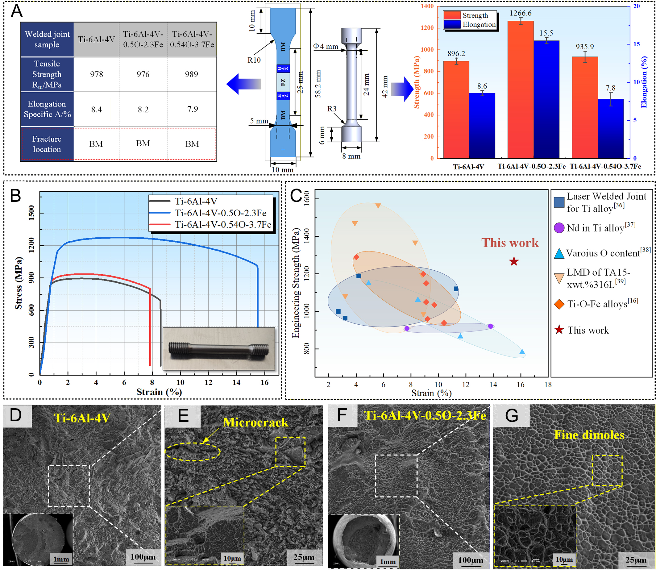
Figure 9. Tensile performance analysis: (A) The results of the tensile test; (B and C) Microalloying composition effects on tensile strength and elongation; (C) Comparative performance with literature data[20,40-43]; (D-G) Macroscopic and microscopic morphology of the tensile fracture surface. Error bars represent the standard deviation based on three independent repetitions (n = 3).
The analysis of the tensile specimens from the pure weld seam area indicates that appropriate O-Fe microalloying simultaneously enhances tensile strength and elongation, achieving unprecedented strength-ductility synergy in titanium alloy welds. The optimal performance was attained with the Ti-6Al-4V-0.5O-2.3Fe composition, which exhibited a tensile strength of 1,266.6 MPa—a 41.3% increase over unalloyed welds—and an improvement in elongation from 8.6% to 15.5% (a 6.9% increase). However, excessive alloying content (Ti-6Al-4V-0.54O-3.7Fe) led to pronounced material embrittlement and reduced elongation, primarily due to synergistic microstructural degradation:
First, the rapid diffusion and severe segregation of excess Fe at grain and phase boundaries promote the formation of a continuous, brittle network of intermetallic compounds [Figure 6G], significantly weakening interfacial cohesion. Concurrently, increased porosity at high alloying levels [Figure 4C1] acts as additional stress concentrators. These intrinsic defects—intergranular brittle phases and pores—directly initiate microcracks. Under tensile loading, these microcracks serve as irreversible damage sites that prematurely exhaust the material’s capacity for uniform plastic deformation, while their tips accelerate damage coalescence. Most critically, they establish a low-energy, intergranular fracture path, resulting in the observed brittle fracture morphology with minimal necking [Figure 9E]. Consequently, despite some grain refinement, the overwhelming presence of these microstructural defects dictates the catastrophic loss of ductility in the excessively alloyed specimen.
Microstructural analysis of the fracture surfaces demonstrates significant differences in failure behavior. The unmodified Ti-6Al-4V weld [Figure 9D and E] displays a flat fracture surface with minimal contraction and no observable necking. High-magnification SEM observations reveal the presence of microcracks within the weld zone, with the fracture surface exhibiting predominant intergranular fracture characteristics resembling a rock-candy morphology. These microstructural features directly correlate with the inferior ductility observed in tensile testing. Comparative analysis of the tensile fracture morphology in Ti-6Al-4V-0.5O-2.3Fe weld demonstrates that O-Fe microalloying induces grain refinement, resulting in significant fracture surface contraction and a transition from brittle to ductile fracture modes. The fracture surface exhibits characteristic fine dimples, indicative of microvoid nucleation, growth, and coalescence during plastic deformation. In summary, the mechanical properties achieved in this study set a new benchmark for titanium alloy welding, surpassing the current state-of-the-art performance metrics in both domestic and international research[20,40-43] [Figure 9C].
DISCUSSION
Phase transformation mechanisms enabling strength-ductility synergy
Previous experimental results have demonstrated a pronounced grain refinement effect induced by O-Fe microalloying. To further elucidate the underlying transformation mechanisms from the perspective of molten-pool solidification behavior, a controlled comparison was conducted to examine the influence of O-Fe addition on the peak molten-pool temperature and the extent of the mushy zone, as illustrated in Figure 10. The results indicate that the incorporation of O-Fe microalloying particles increases the average peak temperature of the molten pool by approximately 88.7 °C compared with the non-microalloyed condition. Simultaneously, the length of the mushy zone is enlarged from 7.72-8.89 mm, suggesting an expanded solid-liquid coexistence region.
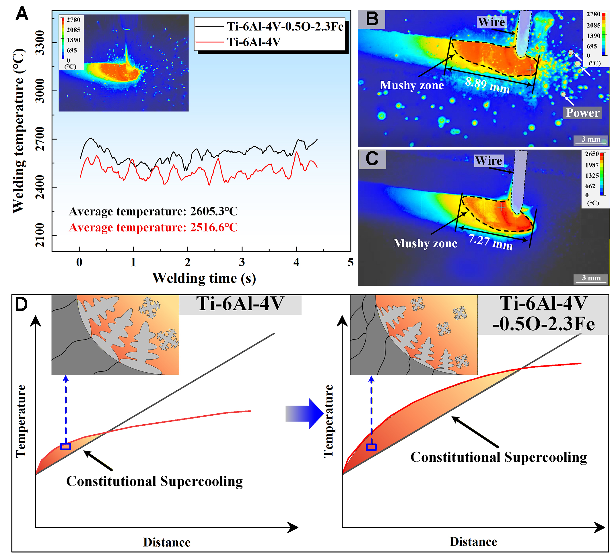
Figure 10. Infrared thermography of molten pool behavior and schematic illustration of solidification conditions during O-Fe microalloyed welding: (A) Comparison of molten-pool peak temperatures with and without O-Fe microalloying; (B and C) Infrared thermal images showing the molten pool and mushy zone length with and without O-Fe microalloying; (D) Grain nucleation mechanism at the solidification front of titanium alloys.
Under steady-state welding conditions, the solidification rate R can be reasonably approximated as proportional to the welding speed, which was maintained constant throughout the experiments. Therefore, variations in the solidification behavior are primarily associated with changes in the thermal gradient G. Infrared thermography measurements further reveal that the addition of Fe and O not only elevates the molten-pool peak temperature but also prolongs the cooling duration under identical processing parameters, indicating a reduced effective cooling rate.
This thermal response is closely related to the role of Fe as a β-Ti stabilizer. During solidification, Fe preferentially partitions into the β phase, reducing its Gibbs free energy and lowering the alloy liquidus temperature, thereby increasing the effective superheat of the molten pool. During subsequent cooling, Fe enrichment decreases the martensite start temperature, enhances β-phase metastability, and suppresses the diffusionless β→α′ martensitic transformation. As a result, the actual transformation temperature T becomes significantly lower than the equilibrium temperature T0, leading to an increased transformation undercooling during subsequent solid-state transformation. The increased superheat and extended thermal field enlarge the molten pool, resulting in a reduced local temperature gradient G. Since the solidification rate R remains approximately constant, the decrease in cooling rate corresponds to a reduced G/R ratio.
Meanwhile, the combined addition of Fe and O enhances solute partitioning at the solidification front, promoting the development of constitutional supercooling ahead of the interface. The synergistic effects of a reduced G/R ratio and an expanded constitutionally supercooled zone suppress columnar grain growth and increase nucleation density, which is consistent with the significant grain refinement observed experimentally.
Ti-6Al-4V as the most widely utilized α + β duplex titanium alloy, exhibits an inherent strength-ductility trade-off due to the ductility disparity between its constituent phases. The α phase (hcp) possesses limited slip systems (primarily basal <a> and prismatic <a> slip), resulting in high strength but poor room-temperature deformability. In contrast, the β phase (bcc) offers numerous slip systems (e.g., {110}<111>), enhancing ductility at the expense of strength. Consequently, achieving α/β interfacial coordination is critical for simultaneous strength-ductility improvement. Extensive studies confirm that the morphological characteristics of α and β phases govern mechanical performance[44,45]. While acicular α phase enable strengthening via dislocation cutting or bypass mechanisms, they also induce stress localization at phase boundaries, promoting microcrack initiation and limiting ductility. Conversely, refining coarse β columnar grains and reducing the aspect ratio of acicular α phase enhance uniform deformation, thereby improving ductility without significant strength loss.
Further analysis of acicular α-phase growth suggests that its pronounced morphological anisotropy originates from crystallographic growth kinetics rather than isotropic atomic diffusion. Owing to the hexagonal close-packed crystal structure of α-Ti, the migration of the α/β interface exhibits strong orientation dependence. In particular, the elongated growth of acicular α laths is favored along specific crystallographic directions, where interface mobility is higher and the local thermodynamic driving force is enhanced at the lath tips.
The high curvature at the tips of lath-shaped α plates increases the local driving force for interface migration, promoting preferential longitudinal growth. In contrast, lateral thickening is comparatively sluggish due to lower interface mobility and geometric constraints. As a result, the growth rate along the long axis significantly exceeds that along the short axis, leading to the progressive development of high-aspect-ratio acicular α morphologies.
Diffusion theory further indicates that the equilibrium concentration of α-stabilizing elements (CR) at acicular α-phase boundaries is strongly dependent on the interfacial curvature radius (R)[46,47], as described by the Gibbs-Thomson relation[48]:
In this formulation, CR and C∞ denote the equilibrium solute concentrations at curved and planar interfaces, respectively, σ is the α/β interfacial energy, V represents the atomic volume of the solute element, kB is the Boltzmann constant, T is the absolute temperature, and R is the interfacial curvature radius.
According to the Gibbs-Thomson relationship, the concentration of α-stabilizing elements (CR) at acicular α-phase boundaries exhibits an inverse correlation with interface curvature radius R. During molten pool solidification, the tip region of acicular α-phase platelets possesses a significantly smaller curvature radius compared to their lateral surfaces. This curvature gradient drives the preferential segregation of α-stabilizing elements to the tip region until reaching local saturation concentration [Figure 11A]. The LM-WPSF modifies the solute distribution in the molten pool, inducing a redistribution of α-stabilizing elements after they reach saturation concentration at acicular α-phase tips. This triggers lateral diffusion along the α-phase interfaces, which enhances precipitation kinetics along the short-axis direction and increases its dimensional growth. The resulting microstructural evolution manifests as progressive spheroidization of the α phase, as evidenced in Figure 11B. This phenomenon is attributed to the combined effects of curvature-driven solute transport and altered interfacial energy distribution during solidification.
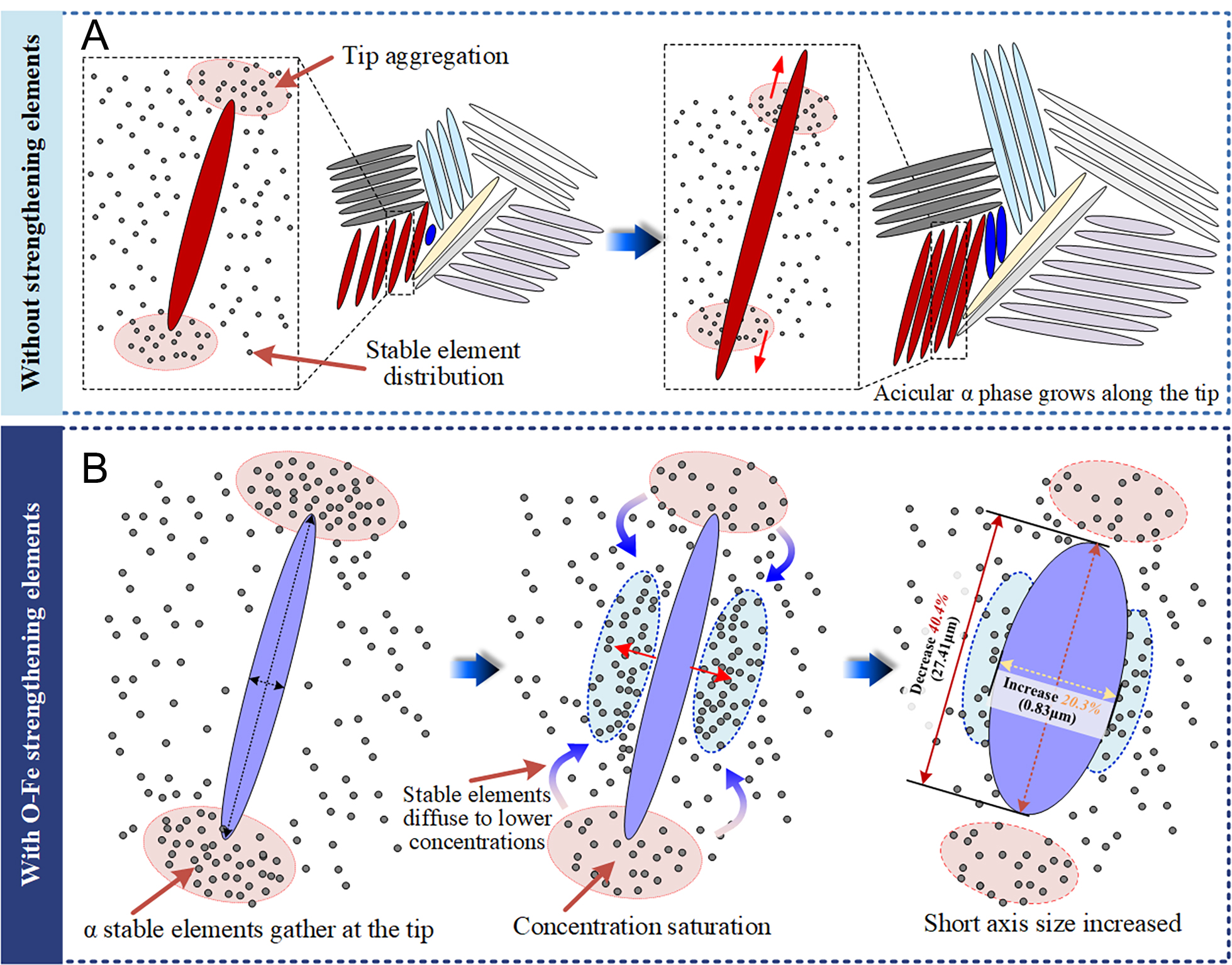
Figure 11. Schematic illustration of stabilizing element distribution and its influence on acicular α-phase growth: (A) Baseline condition; (B) With O-Fe microalloy particle addition.
The spheroidization of acicular α phase was quantitatively confirmed through high-magnification SEM analysis [Figure 5], revealing a 40.4% reduction in average major axis length (from 46.02-27.41 μm) and a 20.3% increase in minor axis diameter (from 0.69-0.83 μm). This reduction in the aspect ratio alleviates stress concentration during deformation, leading to a more uniform strain distribution across the weld seam and, ultimately, enhancing the material's ductility[49,50]. Fractographic analysis further demonstrates this improvement, showing a transition from cleavage fracture with terraced steps to ductile dimple rupture. Correspondingly, the elongation increased by 80.2% (from 8.6%-15.5%), with pronounced necking behavior evident in the fracture cross-section.
The addition of microalloyed powder facilitates the spheroidization of the acicular α phase while also promoting substantial grain refinement in Ti6Al4V welds. EBSD analysis demonstrates a 63.9% reduction in average grain size from 38.43-13.89 μm compared to non-reinforced welds, enabling simultaneous enhancement of both strength and ductility. The microstructural refinement arises from two key mechanisms. Figure 12 provides a schematic of both mechanisms, supported by direct experimental evidence from SEM observations, including particle aggregation and grain refinement. On the one hand, under the influence of alloying elements, the width of columnar grains is significantly reduced, restricting the growth space of α phase within them. Competitive growth is observed between adjacent grains, accompanied by increased intragranular concentrations of α-stabilizing elements, which promote α-phase nucleation and reduce grain size. On the other hand, the Ti-O-Fe microalloying leads to the formation of high-melting-point Fe2Ti4O particles (ilmenite-type structure, ~1,710 °C). As demonstrated in Section "Element distribution and phase composition", these particles preferentially accumulate at multi-pass interlayer fusion zones during wire-powder synchronous deposition. Acting as potent heterogeneous nucleation sites during solidification, they lower the nucleation barrier for α + β phases, increasing nucleation density and further refining the microstructure.
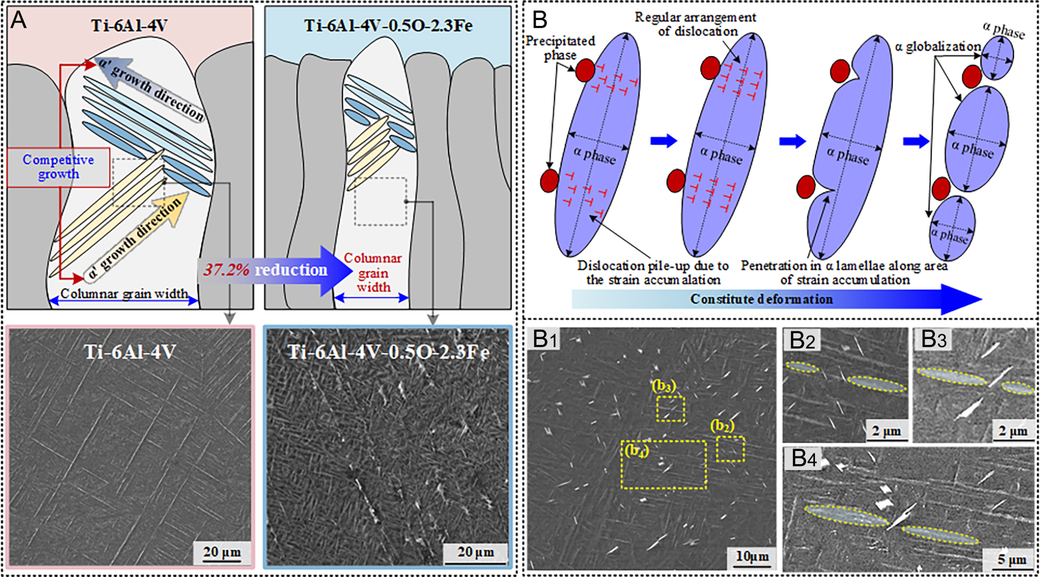
Figure 12. Schematic illustration of grain refinement mechanisms in Ti-O-Fe microalloyed welds: (A) Restricted growth of α/α' phases within narrowed columnar grains due to alloying elements, showing competitive growth behavior; (B) Heterogeneous nucleation of α + β phases at Fe2Ti4O particles (white) formed at interlayer fusion zones.
Strengthening mechanism in the O-Fe microalloyed weld zone
To elucidate the origin of the strength enhancement in the O-Fe microalloyed welds, the individual contributions of the key strengthening mechanisms were estimated based on the measured microstructural parameters and established analytical models. In this study, the enhanced strength of the O-Fe microalloyed welds is examined through a quantitative assessment of several mechanisms, including grain boundary strengthening (∆σgb), solid-solution strengthening (∆σSS), Orowan strengthening (∆σOrowan), thermal-mismatch strengthening (∆σCET) and load-transfer strengthening (∆σload). Given that these mechanisms act concurrently at ambient temperature, their individual strengthening contributions are assumed to follow a linear superposition relationship[51]:
O-Fe microalloying markedly refines the α-phase grains, which constitute the continuous matrix and govern dislocation motion during room-temperature deformation. As the key microstructural feature controlling Hall-Petch strengthening, the α-phase grain size—being one to two orders of magnitude smaller than that of the prior β grains—was measured directly and statistically from EBSD data. Its contribution to overall strengthening was quantitatively evaluated using the Hall-Petch relationship[52]:
where k is the Hall-Petch constant (550 MPa·μm1/2)[53], d₀ and d are the average grain sizes of the base weld and the microalloyed weld, measured as 38.43 μm [Figure 7D] and 13.89 μm [Figure 7I], respectively. This gives a Δσgb value of approximately 58.85 MPa.
The calculation model established for solid solution strengthening to evaluate ΔσSS in the material is as follows[54]:
The solid solution strengthening contributions of oxygen and iron were evaluated using a hybrid strengthening model. In the Ti-O-Fe system, oxygen and iron exhibit fundamentally different dissolution behaviors governed by their atomic sizes and electronic structures. Oxygen (atomic radius ~0.66 Å) dissolves interstitially in both α and β Ti lattices, occupying octahedral/tetrahedral sites and strongly stabilizing the α phase. Iron (atomic radius ~1.26 Å), having a size comparable to Ti (1.46 Å), dissolves substitutionally, preferentially replacing Ti atoms in the β phase and acting as a potent β stabilizer. This distinction is critical for selecting appropriate strengthening models: interstitial solutes follow a C2/3 scaling, whereas substitutional solutes typically exhibit linear strengthening with concentration.
The strengthening coefficients were adopted from established literature on binary Ti-based systems. Based on the reported values[55,56], KO ≈ 4.5 GPa·at%-2/3 and KFe ≈ 1.2 GPa·at%-2/3. Using the compositional conversions CO = 0.5 wt.% ≈ 1.8 at.% and CFe = 2.3 wt.% ≈ 2.3 at.% , the calculated ΔσSS contribution is approximately
The contribution of the analyzed ΔσOrowan to the intensity increment can be expressed as[57]:
The shear modulus μ was taken as the typical value for Ti6Al4V, approximately 42 GPa. The Burgers vector of α-Ti is b ≈ 0.295 nm, and the Poisson’s ratio is v ≈ 0.34. The average precipitate radius was estimated to be  ≈ 0.5 μm, based on the statistical measurements shown in Figure 4. The volume fraction of precipitates was estimated as f ≈ 0.015 based on the SEM images [Figure 6F], the calculated ΔσOrowan contribution is approximately 24.8 MPa.
The contribution of ΔσCET to the increase in yield strength can be calculated using the following equation[58]:
where η is a constant of 1.25. The thermal expansion mismatch between Fe2Ti4O precipitates and the Ti matrix is Δα ≈ 1.5 × 10⁻⁶ K-1. The temperature difference Δt is defined as the difference between the room temperature and the welding temperature. For the O-Fe microalloyed sample, infrared thermometry yielded Δt = 2,580.15 K, resulting in a ΔσCET increment of approximately 23.8 MPa.
The Δσload contribution arising from the interaction between the discontinuous precipitates and the Ti matrix can be expressed as follows[59]:
where σm is the matrix strength of Ti6Al4V, approximately 978 MPa. The precipitate volume fraction f remains constant. Based on the morphology of the uniformly distributed precipitates observed in
The theoretically calculated strengthening increments associated with O-Fe microalloying in Ti-6Al-4V are summarized in Table 4. Among the individual contributions, ΔσSS and Δσgb provide the most significant increases in yield strength. By neglecting other mechanisms—such as the reduction in dislocation density—the theoretical prediction deviates from the experimental yield strength by 16.2 MPa, corresponding to an error of approximately 5.6%.
Estimates of the yield strengthening contributions
| Category | Δσgb | Δσss | ΔσOrowan | ΔσCTE | Δσload | Δσother |
| Increment (MPa) | 58.85 | 182.4 | 24.8 | 23.8 | 14.7 | 16.2 |
| Percentage | 20.39% | 63.19% | 8.59% | 8.25% | 5.09% | 5.61% |
CONCLUSIONS
In summary, this study developed a novel LM-WPSF strategy with O-Fe microalloying to overcome the strength-ductility trade-off in Ti-6Al-4V laser welded joints. The main conclusions are drawn as follows:
1. The LM-WPSF strategy enables precise in-situ microalloying, effectively modifying the thermal-solute field during solidification. This approach successfully suppresses the epitaxial growth of coarse columnar β grains and promotes significant grain refinement within the fusion zone.
2. Trace O-Fe addition regulates the morphological evolution of the acicular α phase. The microalloying elements restrict the anisotropic growth of α/α′ laths, leading to a substantial reduction in their aspect ratio and the formation of a spheroidized microstructure, which mitigates local stress concentrations at phase boundaries.
3. Excellent strength-ductility synergy was achieved in the modified welds. The optimized Ti-6Al-4V-0.5O-2.3Fe alloy exhibited a tensile strength of 1,266.6 MPa and an elongation of 15.5%, demonstrating the significant potential of this strategy for high-performance industrial applications of thick-section titanium alloys.
DECLARATIONS
Authors’ contributions
Methodology, software, writing - original draft, writing - review & editing: Duan, Y.
Validation, funding acquisition: Wang, J.
Formal analysis: Gao, Z.
Investigation: Huang, S.
Data curation: Feng, C.
Supervision, project administration: Zhan, X.
Availability of data and materials
The data that support the findings of this study are available from the corresponding author upon reasonable request.
AI and AI-assisted tools statement
Not applicable.
Financial support and sponsorship
The research was supported by the financial support of the project from the Defense Industrial Technology Development Program (JCKY2024605B011).
Conflicts of interest
All authors declared that there are no conflicts of interest.
Ethical approval and consent to participate
Not applicable.
Consent for publication
Not applicable.
Copyright
© The Author(s) 2026.
REFERENCES
1. Alabort, E.; Barba, D.; Shagiev, M.; et al. Alloys-by-design: application to titanium alloys for optimal superplasticity. Acta. Mater. 2019, 178, 275-87.
2. Barriobero-Vila, P.; Gussone, J.; Stark, A.; Schell, N.; Haubrich, J.; Requena, G. Peritectic titanium alloys for 3D printing. Nat. Commun. 2018, 9, 3426.
3. Dong, Z.; Tian, Y.; Zhang, L.; et al. Research status of high efficiency deep penetration welding of medium-thick plate titanium alloy: a review. Defence. Technol. 2025, 45, 178-202.
4. Choisez, L.; Ding, L.; Marteleur, M.; Idrissi, H.; Pardoen, T.; Jacques, P. J. High temperature rise dominated cracking mechanisms in ultra-ductile and tough titanium alloy. Nat. Commun. 2020, 11, 2110.
5. Devaraj, A.; Joshi, V. V.; Srivastava, A.; et al. A low-cost hierarchical nanostructured beta-titanium alloy with high strength. Nat. Commun. 2016, 7, 11176.
6. Chen, J.; Zheng, P.; Gong, X.; et al. Restoring the ductility of in-situ alloying additively manufactured Ti-Fe alloy via short-time heat treatment. Mater. Sci. Eng. A. 2025, 948, 149320.
7. Dang, N.; Chen, S.; Liu, L.; et al. Analysis of hybrid fracture in α/β titanium alloy with lamellar microstructure. Mater. Sci. Eng. A. 2019, 744, 54-63.
8. Fernández D, Wynne B, Crawforth P, Jackson M. Titanium alloy microstructure fingerprint plots from in-process machining. Mater. Sci. Eng. A. 2021, 811, 141074.
9. Chen, X.; Huang, L.; Ma, S.; Sun, F.; Wang, S.; Geng, L. Multi-scale dispersion strengthening for high-temperature titanium alloys: Strength preservation and softening mechanisms. J. Mater. Sci. Technol. 2025, 206, 1-14.
10. Li, D.; Cheng, J.; Bai, C.; et al. Multi-scale α-phase heterostructure induced transformation-induced plasticity (TRIP) effect in metastable α + β titanium alloy showing excellent strength and work-hardening combination. J. Mater. Proc. Technol. 2025, 341, 118880.
11. Mao, Y.; Zhao, Q.; Zhang, R.; Guo, P.; Chen, Y.; Zhao, Y. Trifunctional local-range order oxygen structure enhanced strength-ductility and fatigue resistance in large-scale metastable titanium alloy. Nat. Commun. 2025, 16, 7168.
12. Wang, J.; Gu, D.; Sun, J.; et al. Achieving strength-ductility synergy in laser powder bed fused near-β titanium alloy via process optimization. J. Mater. Proc. Technol. 2025, 343, 118960.
13. Xian, Y.; Dang, P.; Tian, Y.; et al. Compositional design of multicomponent alloys using reinforcement learning. Acta. Mater. 2024, 274, 120017.
14. Liu, F.; Wang, H.; Meng, X.; Tan, C.; Chen, B.; Song, X. Effect of magnetic field orientation on suppressing porosity in steady-magnetic-field-assisted aluminum alloy deep-penetration laser welding. J. Mater. Proc. Technol. 2022, 304, 117569.
15. Duan, Y.; Wang, J.; Yin, X.; Ma, C.; Zhan, X. Documenting weld pool behavior differences in variable-gap laser self-melting and wire-filling welding of titanium alloys. Int. J. Therm. Sci. 2025, 210, 109550.
16. Gu, K.; Zhao, B.; Weng, Z.; Wang, K.; Cai, H.; Wang, J. Microstructure evolution in metastable β titanium alloy subjected to deep cryogenic treatment. Mater. Sci. Eng. A. 2018, 723, 157-64.
17. Zhang, M.; Li, J.; Tang, B.; et al. Quantification of α phase strengthening in titanium alloys: crystal plasticity model incorporating α/β heterointerfaces. Int. J. Plasticity. 2022, 158, 103444.
18. Oh, J.; Roh, K.; Lim, J. Brief review of removal effect of hydrogen-plasma arc melting on refining of pure titanium and titanium alloys. Int. J. Hydrogen. Energy. 2016, 41, 23033-41.
19. Li, F.; Wang, J.; Huang, K.; et al. Ga-containing Ti alloy with improved osseointegration for bone regeneration: in vitro and in vivo studies. Compos. Part. B. Eng. 2023, 256, 110643.
20. Song, T.; Chen, Z.; Cui, X.; et al. Strong and ductile titanium-oxygen-iron alloys by additive manufacturing. Nature 2023, 618, 63-8.
21. Polmear, I.; John, D. S.; Nie, J. F.; Qian, M. Light alloys: metallurgy of the light metals. Academic Press; 2017. Available from: https://research.monash.edu/en/publications/light-alloys-metallurgy-of-the-light-metals [Last accessed on 11 May 2026].
22. Fu, Y.; Xiao, W.; Zhao, S.; et al. Substantially strengthening a dual-phase titanium alloy by moderate oxygen doping. Scr. Mater. 2023, 226, 115236.
23. Mehjabeen, A.; Xu, W.; Qiu, D.; Qian, M. Redefining the β-phase stability in Ti-Nb-Zr alloys for alloy design and microstructural prediction. JOM 2018, 70, 2254-9.
24. Yang, Q. Y.; Ma, M.; Tan, Y. B.; Xiang, S.; Zhao, F.; Liang, Y. L. Microstructure and texture evolution of TB8 titanium alloys during hot compression. Rare. Metals. 2021, 40, 2917-26.
25. Sandlöbes, S.; Korte-kerzel, S.; Raabe, D. On the influence of the heat treatment on microstructure formation and mechanical properties of near-α Ti-Fe alloys. Mater. Sci. Eng. A. 2019, 748, 301-12.
26. Huang, Y.; Nie, J.; Bai, W.; et al. Diffusivities and atomic mobilities in BCC Ti-Fe-Cr alloys. Materials 2024, 17, 1927.
27. Hong, K.; Shin, Y. C. Prospects of laser welding technology in the automotive industry: a review. J. Mater. Proc. Technol. 2017, 245, 46-69.
28. Fang, N.; Wu, P.; Feng, Z.; et al. A new Ti-Al-Cr-Mo-Zr titanium alloy welding wire: stability, microstructure and mechanical properties. J. Mater. Res. Technol. 2024, 32, 23-36.
29. Fu, J.; Zhao, Y.; Zou, J.; Liu, X.; Pan, Y. Influence of the magnetic field on the melting and solidification behavior of narrow-gap laser welding with filler wire. Int. J. Adv. Manuf. Technol. 2022, 123, 1123-31.
30. Meng, Y.; Li, J.; Zhang, S.; Gao, M.; Gong, M.; Chen, H. Wire arc additive manufacturing of Ni-Al intermetallic compounds through synchronous wire-powder feeding. J. Alloys. Compd. 2023, 943, 169152.
31. Meng, Y.; Li, Z.; Gao, M.; Chen, H.; Wu, X.; Yu, Q. Laser cleaning assisted wire arc additive manufacturing of aluminum alloy thin-wall through synchronous wire-powder deposition. Thin. Walled. Struct. 2024, 197, 111622.
32. Wang, C.; Xing, F.; Xu, G.; Liu, X.; Bian, H.; Liu, W. High addition content WC particle reinforced titanium matrix composites fabricated by concurrent wire powder feeding laser directed energy deposition. Optics. Laser. Technol. 2025, 188, 113026.
33. Wang, C.; Xu, N.; Zhang, G.; Xu, G.; Xing, F. Effect of heat treatment on microstructures and properties of vacuum laser welding Ti-6Al-4V titanium alloy. J. Mater. Res. Technol. 2024, 30, 6309-20.
34. Shi, C.; Wang, Y.; Zhang, M.; Yang, W.; Li, H.; Yang, Z. Refinement of microstructure and improvement of mechanical properties of directed energy deposited titanium alloys by adding Fe. J. Alloys. Compd. 2025, 1010, 176996.
35. Zhou, Z.; Xiang, Z.; Ma, X.; Shen, G.; Chen, Z. Effect of oxygen contents on the fluidity of a newly developed metastable β titanium alloy. Mater. Lett. 2024, 367, 136537.
36. Bai, J.; Zhang, H.; Zhao, Z.; et al. Strong and plastic near-α titanium alloy by Widmanstätten structure spheroidization. J. Mater. Sci. Technol. 2025, 225, 95-110.
37. Xiao, J.; Nie, Z.; Tan, C.; et al. Effect of reverse β-to-ω transformation on twinning and martensitic transformation in a metastable β titanium alloy. Mater. Sci. Eng. A. 2019, 759, 680-7.
38. Liu, J.; Zhan, X.; Gao, Z.; Yan, T.; Zhou, Z. Microstructure and stress distribution of TC4 titanium alloy joint using laser-multi-pass-narrow-gap welding. Int. J. Adv. Manuf. Technol. 2020, 108, 3725-35.
39. Hao, K.; Gong, M.; Pi, Y.; Zhang, C.; Gao, M.; Zeng, X. Effect of Ni content on rolling toughness of laser-arc hybrid welded martensitic stainless steel. J. Mater. Proc. Technol. 2018, 251, 127-37.
40. Wang, J.; Wang, J.; Zhao, Y.; Li, Y.; Zhan, X. Microstructure, thermal behavior and tensile properties of laser welded bottom-locking joint for TA15 titanium alloy. Met. Mater. Int. 2022, 29, 1441-53.
41. Yan, W.; Wang, H.; Tang, H.; Cheng, X.; Zhu, Y. Effect of Nd addition on microstructure and tensile properties of laser additive manufactured TC11 titanium alloy. Trans. Nonferrous. Met. Soc. China. 2022, 32, 1501-12.
42. Sinha, P. K. Influence of an oxygen-enriched layer on the tensile properties of an alpha titanium alloy. Mater. Today. Commun. 2024, 38, 107698.
43. Jin, K.; Liu, C.; Ye, J.; et al. Achieving enhanced tensile strength-ductility synergy through phase modulation in additively manufactured titanium alloys. Mater. Sci. Eng. A. 2024, 909, 146801.
44. Pang, H.; Luo, J.; Li, C.; Li, M. The role of β phase in the morphology evolution of α lamellae in a dual-phase titanium alloy during high temperature compression. J. Alloys. Compd. 2022, 910, 164901.
45. Sadeghpour, S.; Abbasi, S.; Morakabati, M.; Bruschi, S. Correlation between alpha phase morphology and tensile properties of a new beta titanium alloy. Mater. Des. 2017, 121, 24-35.
46. Liu, C.; Wang, H.; Tian, X.; Tang, H.; Liu, D. Microstructure and tensile properties of laser melting deposited Ti-5Al-5Mo-5V-1Cr-1Fe near β titanium alloy. Mater. Sc. Eng. A. 2013, 586, 323-9.
47. Li, T.; Ahmed, M.; Sha, G.; et al. The influence of partitioning on the growth of intragranular α in near-β Ti alloys. J. Alloys. Compd. 2015, 643, 212-22.
48. Lin, M.; Gottstein, G.; Shvindlerman, L. Generalized gibbs-thomson equation for nanoparticles at grain boundaries. Acta. Mater. 2017, 129, 361-5.
49. Xu, W.; Brandt, M.; Sun, S.; et al. Additive manufacturing of strong and ductile Ti-6Al-4V by selective laser melting via in situ martensite decomposition. Acta. Mater. 2015, 85, 74-84.
50. Tan, X.; Kok, Y.; Tan, Y. J.; et al. Graded microstructure and mechanical properties of additive manufactured Ti-6Al-4V via electron beam melting. Acta. Mater. 2015, 97, 1-16.
51. Zhang, Z.; Cheng, Y.; Wang, X.; Song, S.; Ren, X. Investigation on tensile property and mechanism of partially recrystallized Al0.1CoCrFeNi high-entropy alloy after cold rolling and annealing treatment. Mater. Sci. Eng. A. 2025, 921, 147572.
52. Li, S.; Li, S.; Liu, L.; et al. High-temperature “Inverse” Hall-Petch relationship and fracture behavior of TA15 alloy. Int. J. Plasticity. 2024, 176, 103951.
53. Shao, H.; Huang, S.; Ma, Y.; et al. Quantitative investigation of the effects of basketweave microstructure on mechanical strength of α + β titanium alloy. J. Mater. Res. Technol. 2025, 37, 4991-5002.
54. Lugovy, M.; Slyunyayev, V.; Brodnikovskyy, M. Solid solution strengthening in multicomponent fcc and bcc alloys: analytical approach. Prog. Nat. Sci. Mater. Int. 2021, 31, 95-104.
55. Labusch, R. A statistical theory of solid solution hardening. Phys. Status. Solidi. (b). 2006, 41, 659-69.
56. Kariya, S.; Issariyapat, A.; Bahador, A.; Qian, M.; Umeda, J.; Kondoh, K. Microstructure and strengthening mechanism of Fe-supersaturated α Titanium alloy produced by laser powder bed fusion. Mater. Trans. 2025, 66, 1313-8.
57. Song, H.; Wang, H.; Wang, Y.; et al. Preparation of ultrafine acicular α' phase titanium alloys via laser melting deposition: Achieving synergistic enhancement of strength and corrosion resistance. J. Alloys. Compd. 2025, 1042, 184126.
58. Huang, X.; Gao, Y.; Wang, Z.; Yi, Y.; Wang, Y. Microstructure, mechanical properties and strengthening mechanisms of in-situ prepared (Ti5Si3 + TiC0.67)/TC4 composites. J. Alloys. Compd. 2019, 792, 907-17.
Cite This Article
How to Cite
Download Citation
Export Citation File:
Type of Import
Tips on Downloading Citation
Citation Manager File Format
Type of Import
Direct Import: When the Direct Import option is selected (the default state), a dialogue box will give you the option to Save or Open the downloaded citation data. Choosing Open will either launch your citation manager or give you a choice of applications with which to use the metadata. The Save option saves the file locally for later use.
Indirect Import: When the Indirect Import option is selected, the metadata is displayed and may be copied and pasted as needed.
About This Article
Special Topic
Copyright

Data & Comments
Data
0


Comments
Comments must be written in English. Spam, offensive content, impersonation, and private information will not be permitted. If any comment is reported and identified as inappropriate content by OAE staff, the comment will be removed without notice. If you have any queries or need any help, please contact us at [email protected].