

fig8
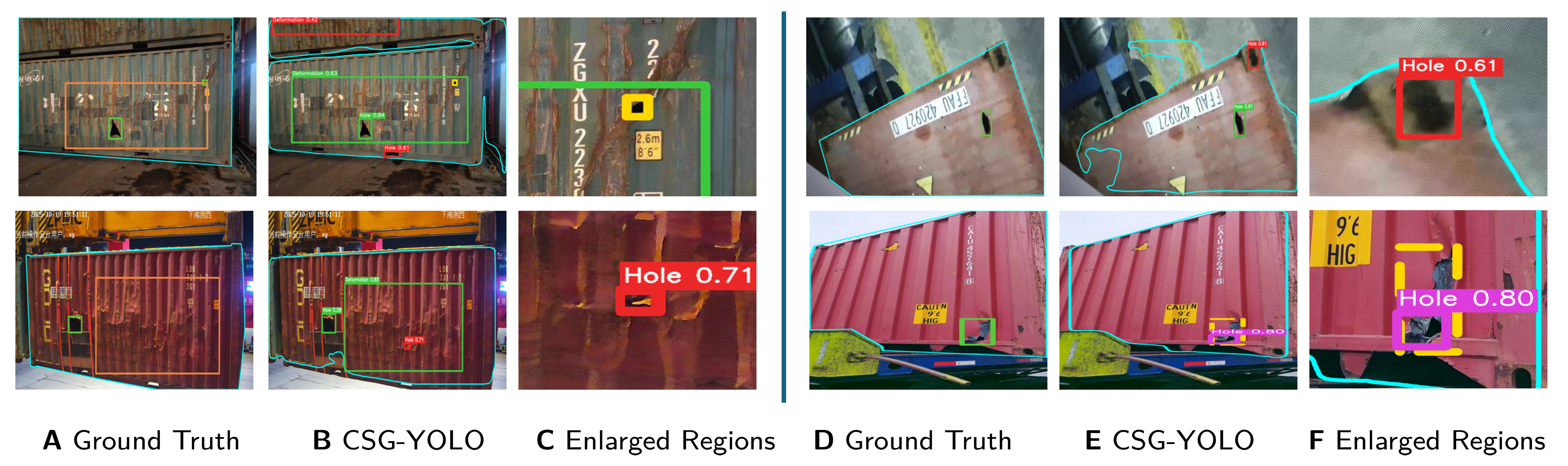
Figure 8. Four illustrative failure cases of CSG-YOLO in a 2 × 2 layout. Within each half of the figure, columns A-C (left) and D-F (right) show ground-truth annotations, model predictions, and enlarged regions, respectively. Surface contours in columns A and D denote ground-truth container-surface boundaries, whereas those in columns B and E denote predicted boundaries. The upper-left case shows a missed tiny hole; the lower-left case shows a reflection-induced false positive alongside an occluded true hole; the upper-right case shows confusion with locking hardware and mask spillover; and the lower-right case shows incomplete localization near the panel–beam boundary.