

fig7
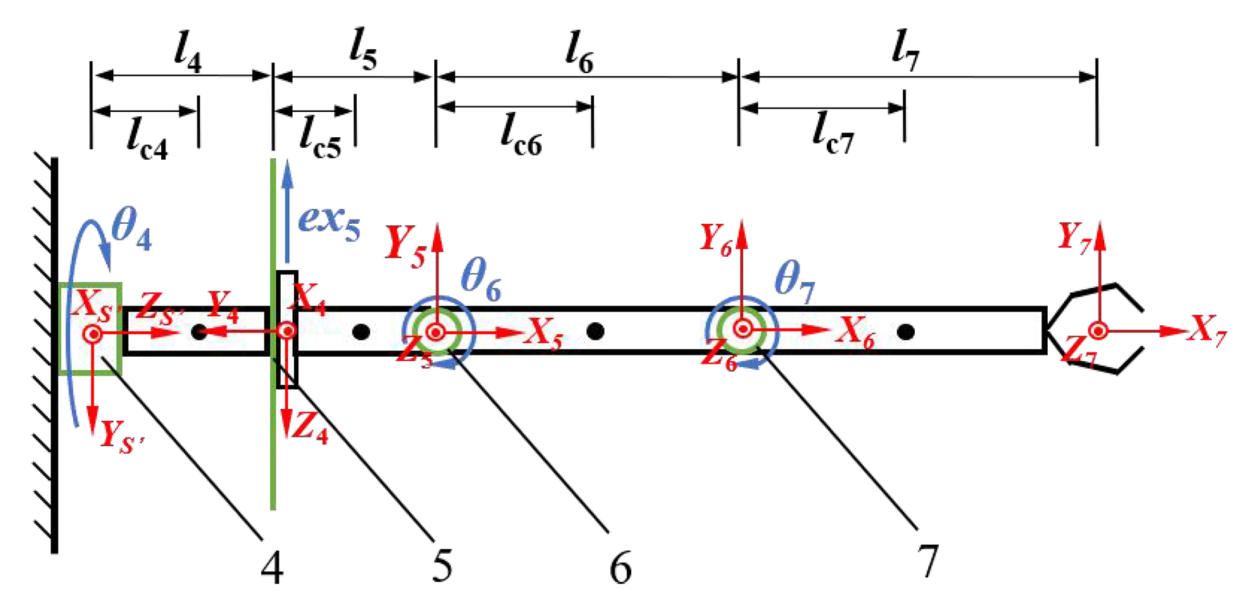
Figure 7. Dynamic model of the picking mechanism. O0’X0’Y0’Z0’ denotes the initial coordinate frame of the picking mechanism; joints 4-7 correspond to joints 4-7, respectively. The axes Xi, Yi, and Zi (i = 4, 5, 6, 7) correspond to the coordinate frame OiXiYiZi attached to joint i. Among these joints, 4, 6, and 7 are rotational, whereas joint 5 is translational. The positive directions of the XS′, X4, Z5, and Z6 axes are perpendicular to the plane of the page and point outward.