

Thick electrodes for high-energy rechargeable lithium batteries: degradation mechanisms, architectural strategies, and capacity-utilization metrics
 0

Graphical Abstract
Abstract
Thick electrodes can increase the cell-level energy density of rechargeable lithium (Li) batteries, including liquid-electrolyte Li-ion batteries (LIBs) and all-solid-state Li batteries, by increasing active material loading and reducing the relative fraction of inactive components. However, increased electrode thickness does not guarantee a proportional increase in achievable areal capacity because ion/electron transport, electrolyte accessibility, reaction distribution, and interfacial stability become increasingly limiting under high-loading conditions. This review summarizes the degradation mechanisms that govern thick-electrode performance, focusing on tortuosity-driven ionic transport and electrolyte infiltration limitations, through-thickness concentration polarization, reaction heterogeneity, and resistance buildup. We then discuss how these limitations manifest as electrode-level degradation, including cathode-side active-material underutilization, interfacial byproduct accumulation, particle/contact deterioration, anode-side Li trapping, localized Li plating, and excessive solid electrolyte interphase growth. Recent mitigation strategies are reviewed in terms of low-tortuosity architectures, multilayer and gradient electrodes, conductive network engineering, and model- and diagnostics-guided design. Finally, we argue that designed areal capacity alone is insufficient for evaluating practical thick electrodes. Achievable areal capacity, operating current density, and capacity utilization should be reported together to distinguish nominally high-loading electrodes from electrodes that deliver accessible capacity under relevant operating conditions. This review provides mechanistic and design perspectives for translating high active material loading into practical areal capacity in high-energy rechargeable Li batteries.
Keywords


 Download PDF
INTRODUCTION
The rapid expansion of electric vehicles and high-power portable electronics has placed rechargeable lithium (Li) batteries at the center of modern energy-storage technologies. Liquid-electrolyte Li-ion batteries (LIBs) currently dominate commercial applications, whereas all-solid-state batteries (ASSBs) are being developed as next-generation high-energy systems[1-6]. Although their electrolyte phases and cell configurations differ, both systems face a common electrode-level constraint: increased active material loading contributes to practical energy density improvement only when ion transport, electron conduction, electrolyte accessibility, and reaction homogeneity are sustained throughout the electrode thickness. In practical cells, cell-level energy density is directly linked to driving range, operation time, pack volume, and system cost[7-14]. Accordingly, substantial research has focused on increasing the reversible capacity and operating voltage of electrode materials through high-Ni cathodes, Si-containing anodes, Li-rich compounds, and advanced electrolyte formulations[15-28]. However, as state-of-the-art electrode materials continue to improve, the bottleneck for further energy-density improvement is increasingly shifting from intrinsic material capacity to electrode- and cell-level structural design[29-33].
Electrochemically inactive components, including current collectors, separators, electrolytes, binders, and conductive additives, occupy a substantial fraction of the total mass and volume of practical cells[29,34,35]. Although these components are indispensable for mechanical support, ionic/electronic transport, and cell safety, they dilute the contribution of active materials to total energy output. High-capacity materials therefore need to be coupled with electrode architectures that increase the active material fraction within a fixed cell footprint[36-38].
Thick electrode architectures provide an effective strategy for increasing active material loading while reducing the fraction of inactive components at the cell level, thereby improving energy density and manufacturing efficiency. Quantitative estimates indicate that increasing electrode thickness from 25 µm (≈ 8 mg cm-2) to 200 µm (≈ 64 mg cm-2) reduces the inactive component ratio from 44 to 12 wt.%[30]. Assuming a tap density of 3.2 g cm-3 for the active materials and excluding packaging dimensions, this structural modification increases the active material fraction from 56 to 88 wt.%, underscoring the potential of thick electrodes for high-energy-density battery systems [Figure 1A][30].
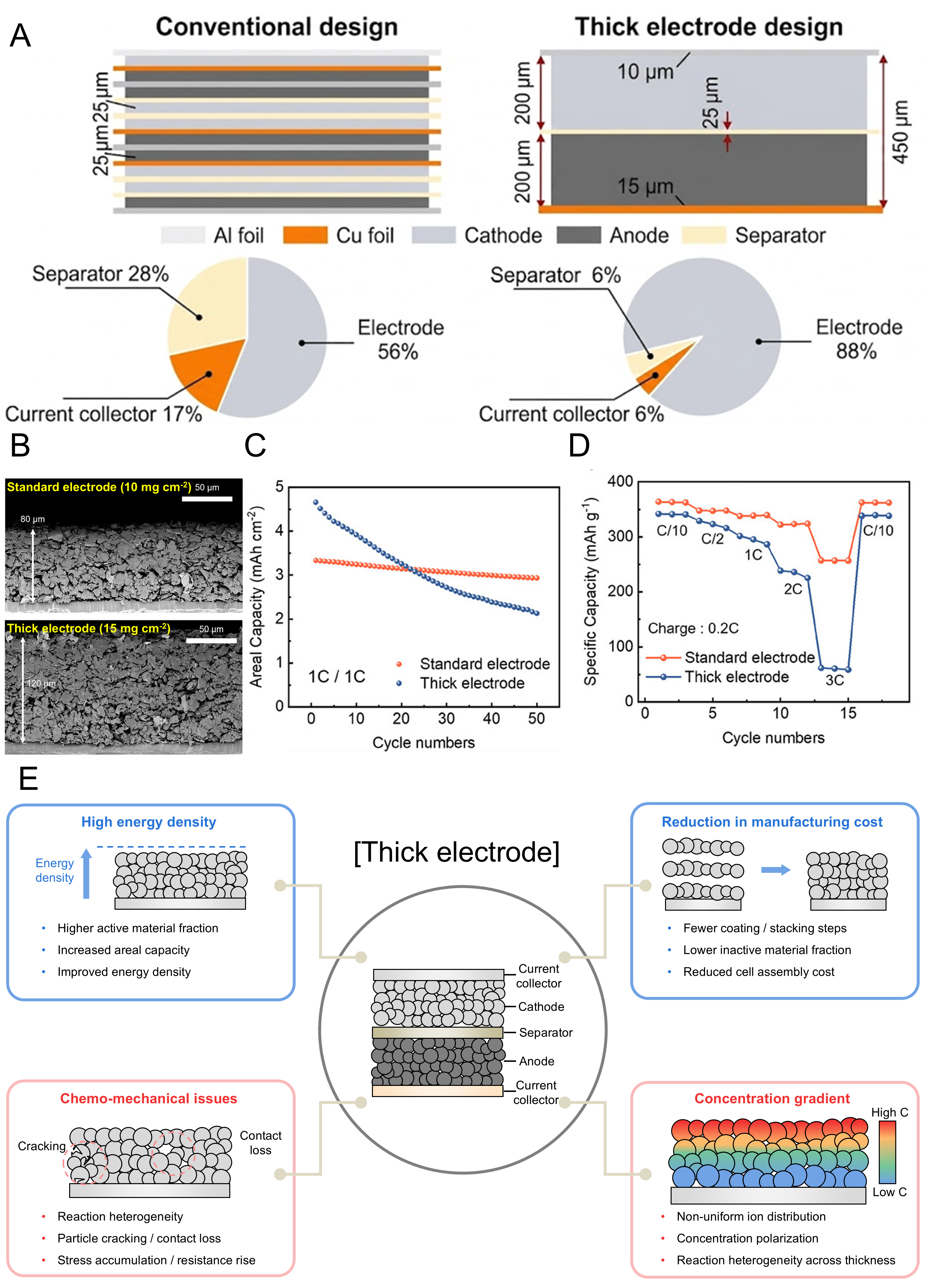
Figure 1. (A) Schematic illustration of battery component ratios based on thin electrodes and a thick electrode configuration; (A) is reprinted with permission from Ref.[30], Copyright © 2019 Wiley; (B-D) Comparison between standard and thick graphite electrodes; (B) Cross-sectional SEM images, (C) cycling performance and (D) rate capabilities; (B-D) are reprinted with permission from Ref.[39], under CC BY NC-ND license; (E) schematic illustration of the advantages and key technical challenges associated with thick electrode architectures. SEM: Scanning electron microscopy.
Despite these advantages, the electrochemical benefits of thick electrodes are not always fully realized under practical operating conditions. Ko et al. systematically compared graphite electrodes with conventional and thick mass loadings of 10 and 15 mg cm-2, respectively. Although the thick graphite electrode initially provided higher areal capacity, it exhibited faster capacity decay and inferior high-current retention than the conventional-loading electrode [Figure 1B-D][39]. This comparison highlights the distinction between nominal loading or designed areal capacity and electrochemically accessible capacity. Increased electrode thickness can intensify Li+ transport limitations, concentration polarization, nonuniform reaction distribution, and incomplete active-material utilization. Thus, thick electrodes offer clear advantages in energy density and manufacturing efficiency only when the accompanying transport-, reaction-, and structure-related challenges are controlled [Figure 1E].
Previous reviews have established the fundamental principles, transport limitations, architectural strategies, and manufacturing considerations associated with thick and high-loading electrodes[30,36,37]. However, a remaining need is to directly connect these degradation mechanisms and design strategies with the extent to which increased electrode loading is translated into electrochemically accessible capacity under practically relevant operating conditions. In particular, high designed areal capacity alone does not indicate whether the loaded active material can be effectively utilized at a meaningful current density. From this perspective, capacity utilization provides a useful link between electrode design and practical electrochemical output by describing the fraction of designed areal capacity that can be delivered under a specified operating condition. Accordingly, the central perspective of this Review is not simply how much active material can be incorporated into an electrode, but how effectively that loading can be converted into achievable areal capacity without sacrificing operating current density.
Based on this perspective, this Review provides a mechanistic analysis of the key limitations associated with thick electrode architectures and relates these limitations to practical capacity utilization. Tortuosity-driven ionic transport and electrolyte infiltration limitations, through-thickness concentration polarization, reaction heterogeneity, and electrode-level degradation are discussed as interconnected factors that determine the gap between designed and achievable areal capacity. We then critically examine low-tortuosity architectures, multilayer and gradient designs, conductive-network engineering, and model- and diagnostics-guided optimization in terms of how effectively they improve transport, reaction uniformity, and active-material utilization. Where appropriate, limitations shared by LIBs and ASSBs are distinguished from electrolyte-specific constraints, including liquid-electrolyte wetting and pore-scale infiltration in porous electrodes and solid-ion-conductor percolation and catholyte distribution in composite cathodes. Throughout this Review, designed areal capacity, achievable areal capacity, operating current density, and capacity utilization are considered together to provide a practical framework for evaluating whether high active material loading can be translated into accessible electrochemical capacity.
DEGRADATION MECHANISMS OF THICK ELECTRODES
Tortuosity-driven ionic transport and electrolyte infiltration limitations
As electrode thickness increases, ion transport through the porous electrode network becomes increasingly constrained by elongated and tortuous pathways[40-47]. Tortuosity is therefore a key structural parameter governing ionic resistance, electrolyte accessibility, and reaction homogeneity in thick electrodes. In porous electrodes, increased tortuosity generally decreases the effective ionic conductivity and diffusivity of the electrolyte phase[40-47]. This relationship is often approximated as κeff ∝ ε/τ and Deff ∝ ε/τ, where ε and τ denote porosity and tortuosity, respectively, although the exact dependence may vary with the tortuosity model and pore-network characteristics. Importantly, the transport penalty associated with electrode thickening is not determined solely by the increased Li+ transport distance, because thickness-dependent changes in pore connectivity and accessibility can further amplify the effective ionic resistance. Neidhart et al. showed that electrode thickening can intensify ionic transport limitations by increasing tortuosity within the porous electrode network[48]. Cross-sectional images of NMC811 cathodes with different coating thicknesses show an increase in electrode thickness from 36 µm, corresponding to 1.54 mAh cm-2, to 170 µm, corresponding to 8.60 mAh cm-2 [Figure 2A and B]. To quantify ionic transport resistance, the authors employed electrochemical impedance spectroscopy under blocking conditions and analyzed the response using a simplified transmission-line model [Figure 2C]. With increasing electrode thickness, tortuosity remained moderate below approximately 150 µm but increased sharply beyond this threshold. Ionic resistance followed the same thickness-dependent trend, as evidenced by the Rion values and enlarged impedance responses in the Nyquist plots [Figure 2D-F]. These results demonstrate that electrode thickening affects ionic transport through both an extended transport distance and thickness-dependent changes in the internal pore network. The resulting increase in tortuosity and ionic resistance progressively limits the ability of the electrolyte phase to sustain uniform Li+ transport across the electrode depth.
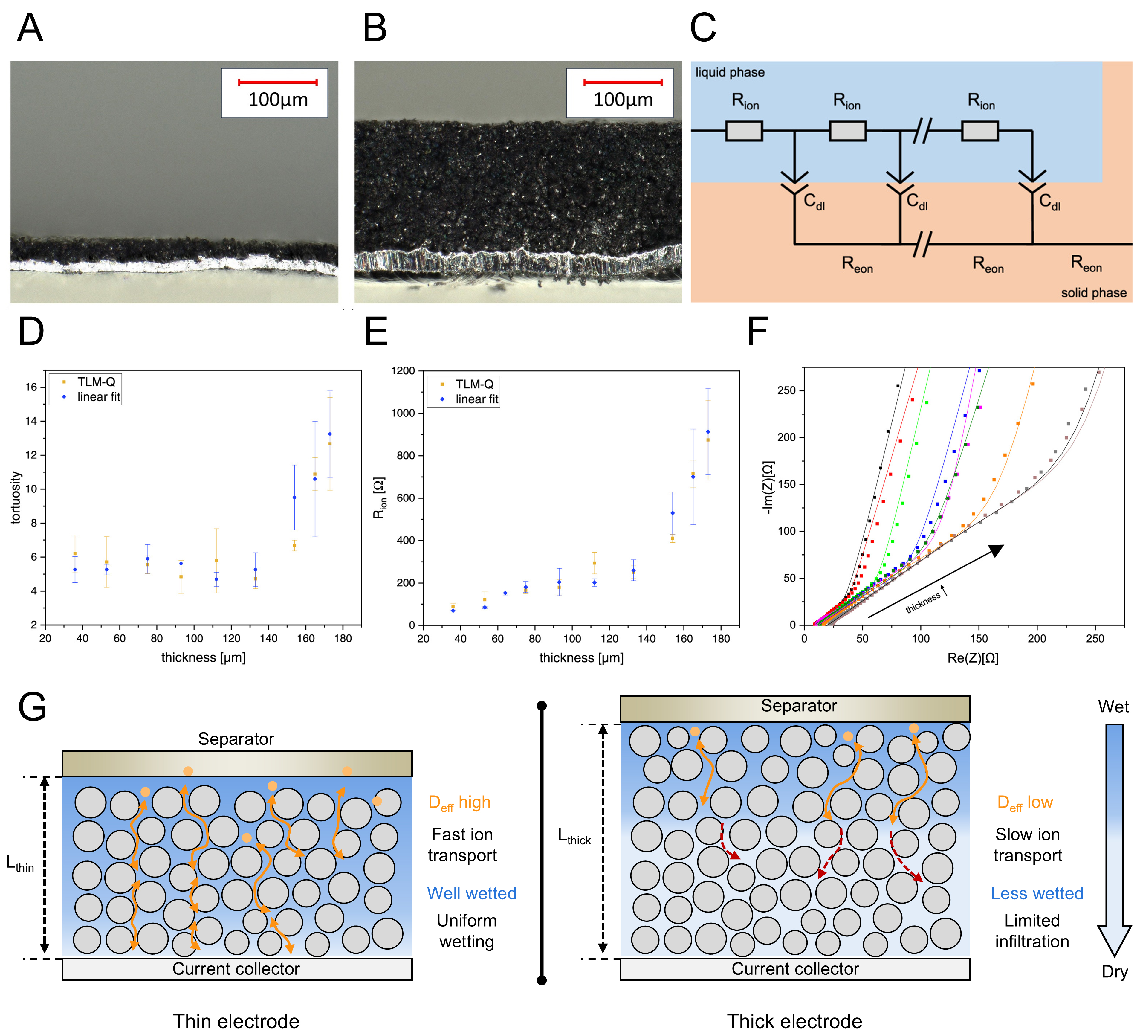
Figure 2. (A and B) Cross-sectional images of NMC811 cathodes with coating thicknesses of (A) 36 μm and (B) 170 μm, respectively; (C) simplified transmission-line model under blocking conditions; (D) tortuosity (τ) as a function of coating thickness; (E) thickness dependence of Rion; (F) Nyquist plots and corresponding fits for NMC811 electrodes with different thicknesses; (A-F) are reprinted with permission from Ref.[48] under a CC BY 4.0 license; (G) schematic illustration of electrolyte infiltration behavior in thin and thick electrodes. TLM: Transmission-line model; NMC811: LiNi0.8Mn0.1Co0.1O2.
Li et al. further showed that increased tortuosity in thick LiCoO2 electrodes is closely associated with limited electrolyte infiltration[49]. Increasing the LiCoO2 loading from 20 to 50 mg cm-2 increased the electrode thickness from 68 to 190 µm, reduced porosity by 46%, and increased tortuosity by 33%. This pore-structure evolution reduced electrolyte permeability by 90% and the effective ion-transport coefficient by 60%, ultimately decreasing capacity retention from 80% to 14%. These observations indicate that increased tortuosity and restricted electrolyte infiltration should not be regarded as independent limitations. Instead, both originate from thickness-dependent changes in the pore network and collectively reduce ionic accessibility within the inner electrode region [Figure 2G][50-53]. Thus, transport limitations in thick electrodes can be described not only as a consequence of extended diffusion length, but also as a coupled structural effect involving increased tortuosity, reduced pore accessibility, and less effective electrolyte infiltration. As these limitations increasingly restrict Li+ supply toward the inner electrode region, the local reaction demand can no longer be uniformly supported throughout the electrode thickness. This mismatch between local Li+ supply and electrochemical reaction demand consequently generates through-thickness concentration polarization, resulting in spatially heterogeneous reaction kinetics and incomplete active-material utilization[54].
Through-thickness concentration polarization
When ionic transport cannot sustain the local electrochemical reaction demand throughout a thick electrode, Li+ availability becomes increasingly nonuniform along the electrode depth, giving rise to through-thickness concentration polarization[55-60]. Under transport-limited conditions, this spatial imbalance leads to preferential reaction in regions with more favorable Li+ access and delayed electrochemical participation in less accessible regions, thereby producing depth-dependent reaction heterogeneity. Min et al. investigated the thickness dependence of transport limitations in all-active-material lithium-ion cells using electrochemical modeling[61]. The simulated Li+ concentration profiles revealed increasingly pronounced spatial gradients as the electrode thickness increased [Figure 3A and B]. Under these transport-limited conditions, the separator-facing region was supplied with Li+ more readily and reacted earlier, whereas the current-collector-facing region exhibited delayed reaction kinetics and insufficient ionic access. Consequently, the cell can reach the prescribed cut-off voltage before the entire electrode thickness is electrochemically utilized, leaving a fraction of the loaded active material incompletely accessed. The resulting reaction state therefore becomes progressively depth-dependent, with different electrode regions approaching their local end-of-charge or end-of-discharge conditions at different times.
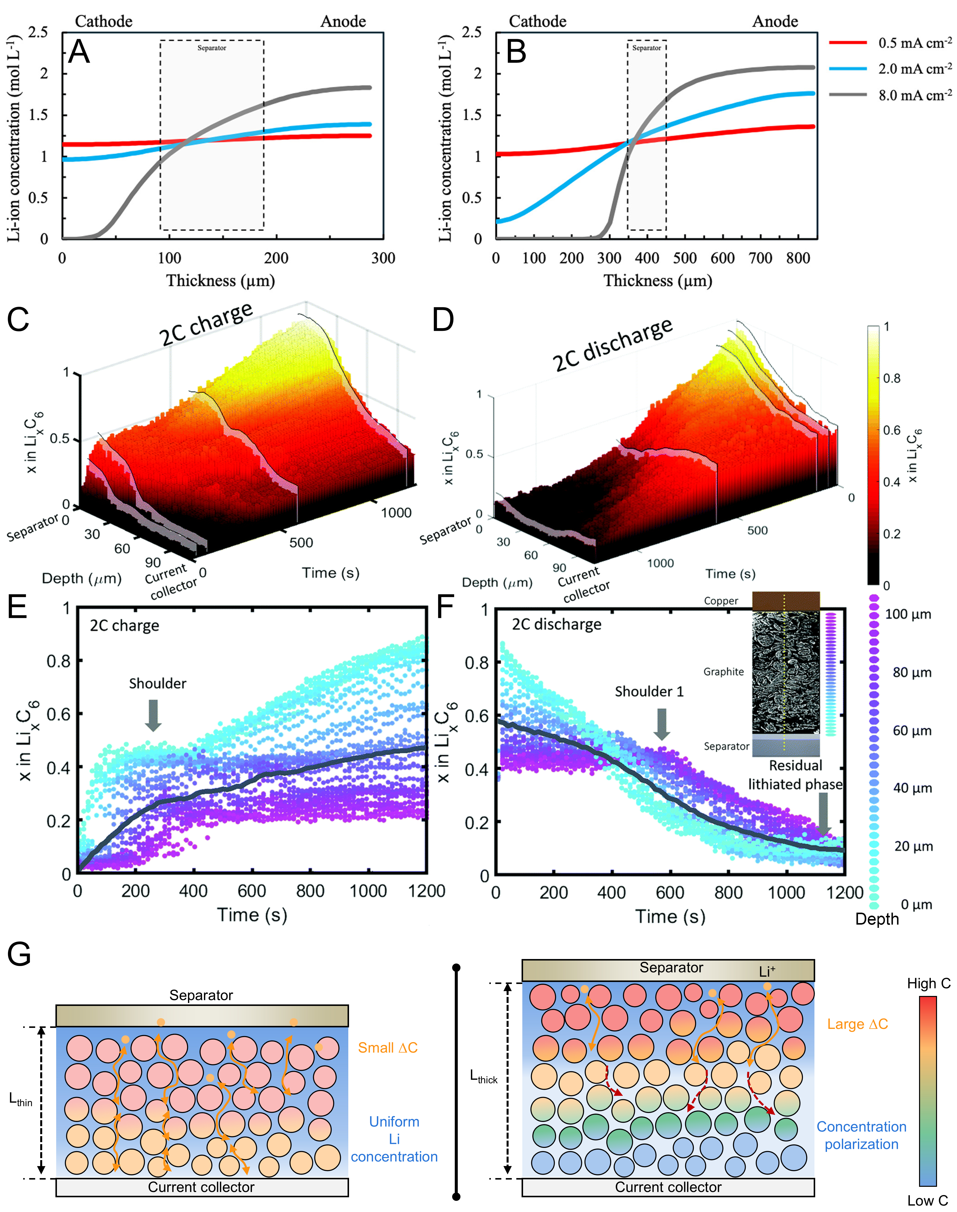
Figure 3. (A and B) Li+ concentration extracted from P2D simulations as a function of cell thickness; (A) thin and (B) thick electrodes; (A and B) are reprinted with permission from Ref.[61] under a CC BY 4.0 license; (C-F) 3D and scatter plots of XRD point measurements, color-coded by depth, showing LixC6 value as a function of time and depth during 2C (C and E) charge, and (D and F) discharge; (C-F) are reprinted with permission from Ref.[62] under a CC BY 3.0 license; (G) Schematic illustration of thickness-dependent Li+ concentration gradients in thin and thick electrodes. XRD: X-ray diffraction.
Consistent with this transport-induced spatial imbalance, Finegan et al. experimentally visualized depth-dependent lithiation in a 101 μm graphite electrode using high-speed pencil-beam X-ray diffraction (XRD)[62]. The depth-resolved diffraction profiles revealed that lithiation preferentially proceeded in the separator-facing region, while the reaction in the current-collector-facing region was delayed under high-rate operation [Figure 3C-F]. The increasing reaction gradient at higher current demonstrates that concentration polarization is governed not only by electrode thickness itself but by the balance between ionic transport capability and electrochemical reaction demand. Collectively, through-thickness concentration polarization represents the spatial manifestation of an imbalance between ionic transport and electrochemical reaction demand in thick electrodes. The resulting depth-dependent reaction distribution causes some regions to undergo preferential electrochemical cycling while other regions remain incompletely utilized, thereby widening the gap between designed and achievable areal capacity. At the same time, localized reaction intensification can create spatially nonuniform electrochemical environments that promote subsequent electrode and interfacial degradation [Figure 3G][63-69].
ELECTRODE-LEVEL DEGRADATION IN THICK ELECTRODES
Coupled electrode degradation in liquid-electrolyte LIBs
In liquid-electrolyte LIBs, transport limitations in thick electrodes manifest differently at the cathode and anode but collectively determine full-cell degradation. Restricted Li+ transport and through-thickness concentration polarization induce depth-dependent reaction heterogeneity in both electrodes, resulting in local overutilization, active-material underutilization, and progressive interfacial degradation. Because the cathode and anode operate under the same applied current, degradation occurring at either electrode contributes to the overall polarization and capacity loss of the full cell. Therefore, cathode- and anode-side degradation need to be considered together to understand how thickness-induced transport limitations affect practical full-cell performance.
At the cathode, transport limitations can induce pronounced depth-dependent reaction heterogeneity. Won et al. systematically compared reference and thick LiFePO4 electrodes with active material loadings of 9 and 18 mg cm-2, corresponding to electrode thicknesses of approximately 75 and 150 µm, respectively[70]. Although the two electrodes exhibited comparable electrochemical behavior at low current density, the thick electrode showed pronounced capacity decay at 1C, indicating that increased electrode thickness imposes severe kinetic constraints during repeated cycling. To identify the origin of this degradation, the authors divided the electrodes into separator-facing and current-collector-facing regions and analyzed their phase evolution using ex situ XRD. In the reference electrode, both regions showed reversible phase conversion between LiFePO4 and FePO4 after 100 cycles, indicating relatively homogeneous electrochemical reactions throughout the electrode thickness [Figure 4A and B]. In contrast, the thick electrode exhibited clear depth-dependent reaction imbalance. The separator-facing region showed dominant FePO4 and LiFePO4 features at the charged and discharged states, respectively, whereas the current-collector-facing region retained mixed LiFePO4/FePO4 characteristics even after full charge and discharge [Figure 4C and D]. The retained mixed LiFePO4/FePO4 signature in the current-collector-facing region is consistent with incomplete electrochemical participation associated with restricted Li+ transport across the electrode thickness.
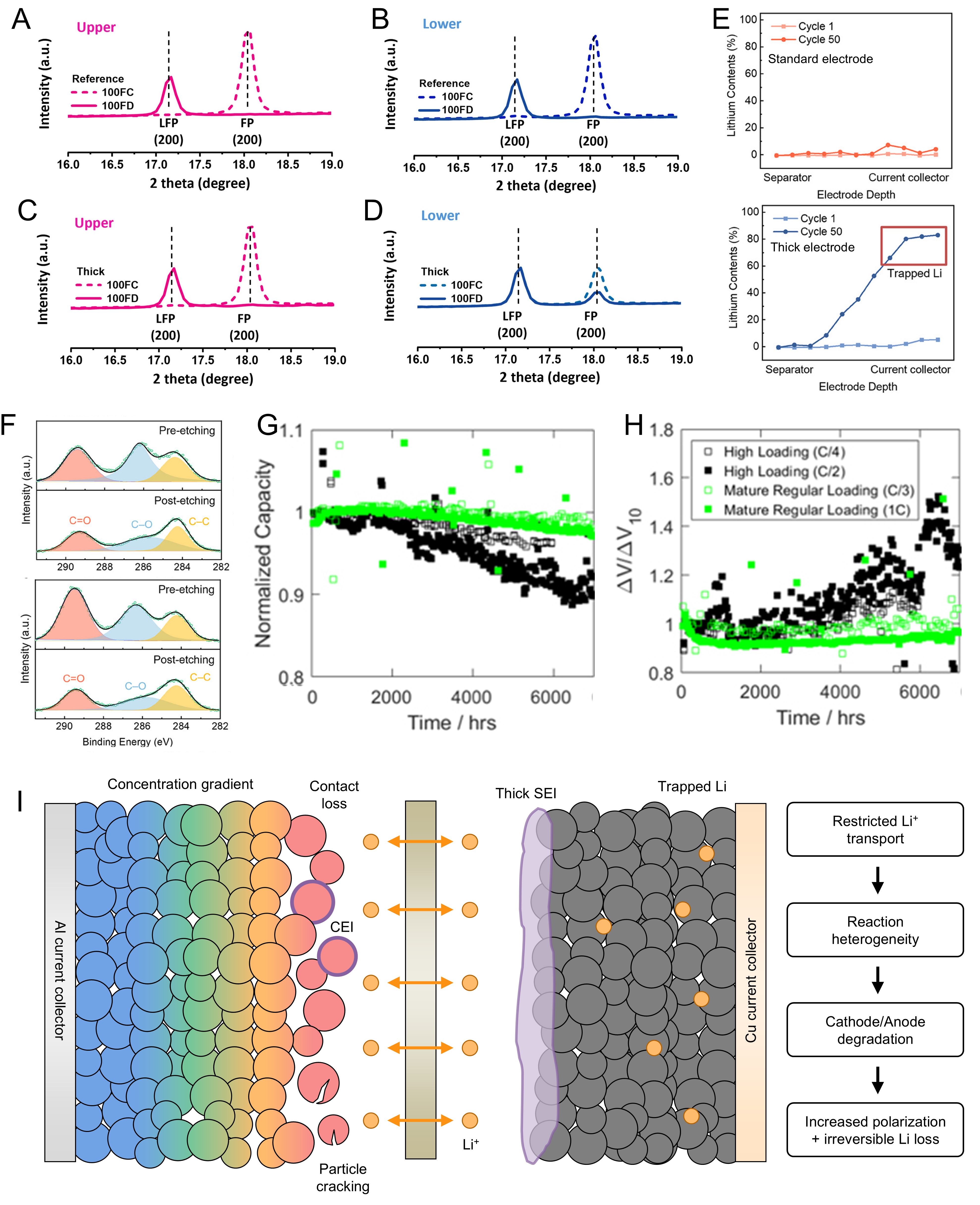
Figure 4. (A-D) Ex situ XRD patterns of the separator-facing and current-collector-facing regions of reference (A and B) and thick (C and D) LiFePO4 cathodes at the 100th charge and discharge states; (A-D) are reprinted with permission from Ref.[70] under a CC BY 4.0 license; (E) depth-resolved Li distribution obtained by laser-induced breakdown spectroscopy and (F) XPS results of cycled standard and thick graphite electrodes; (E and F) are reprinted with permission from Ref.[39], under CC BY NC-ND license; (G) normalized capacity retention and (H) normalized voltage polarization of regular- and high-loading NMC532/graphite pouch cells cycled at 20 °C under different C-rates; (G and H) are adapted from Ref.[91] under a CC BY 4.0 license; (I) schematic illustration of coupled degradation mechanisms in high-loading liquid-electrolyte LIBs. LFP: Lithium iron phosphate; FP: iron phosphate; CEI: cathode electrolyte interphase; SEI: solid electrolyte interphase; XRD: X-ray diffraction; NMC532: LiNi0.5Mn0.3Co0.2O2; XPS: X-ray photoelectron spectroscopy; LIB: Li-ion battery.
This nonuniform reaction distribution further accelerates interfacial degradation and resistance buildup. In thick cathodes, the separator-facing region undergoes more intensive electrochemical cycling because Li+ access is more favorable in the separator-facing region, while the current-collector-facing region remains relatively underutilized[71-78]. This locally concentrated reaction promotes electrolyte decomposition and cathode electrolyte interphase (CEI)/byproduct accumulation at the cathode surface, which further increases kinetic resistance. In cathode materials that undergo pronounced lattice strain during cycling, such as Ni-rich layered cathodes, repeated local overutilization can further promote particle cracking, interparticle contact loss, and irreversible structural degradation[77-80]. Although these degradation phenomena are not limited to thick electrodes, spatially nonuniform reactions can intensify their occurrence within preferentially utilized regions. Therefore, cathode-side degradation in thick electrodes can be described as a transport-mediated process involving depth-dependent reaction heterogeneity, local overutilization in the separator-facing region, underutilization in the current-collector-facing region, interfacial byproduct accumulation, particle/contact degradation, and progressive resistance buildup[81-85].
On the anode side, transport limitations promote degradation through depth-dependent lithiation inhomogeneity and localized Li plating. Ko et al. compared standard and thick graphite electrodes with mass loadings of 10 and 15 mg cm-2, corresponding to electrode thicknesses of approximately 80 and 120 µm, respectively[39]. The thick graphite electrode initially delivered a higher areal capacity than the standard electrode, but this gain was accompanied by rapid capacity decay during repeated 1C cycling. Laser-induced breakdown spectroscopy revealed that the Li content remained relatively uniform across the standard electrode after both the initial and 50th cycles, whereas the thick electrode exhibited pronounced Li accumulation in the current-collector-facing region after prolonged cycling. In particular, more than 80% of Li remained trapped in the current-collector-facing 30% of the thick electrode even after full delithiation to 1.6 V [Figure 4E][39]. This depth-dependent Li trapping indicates that the current-collector-facing region becomes progressively less accessible to reversible cycling, while a larger fraction of the electrochemical reaction is concentrated in the separator-facing region.
The localized reaction in the separator-facing region further promotes anode surface degradation. Because the current-collector-facing region contributes less effectively to charge storage, the effective local current density becomes concentrated in the more electrochemically accessible region during lithiation, thereby increasing the susceptibility to Li plating. Ko et al. observed a decrease in LiC12 and an increase in LiC6 during a 16 h rest period after lithiation in the thick electrode, whereas the standard electrode showed minimal changes[39]. This relaxation-induced phase evolution was attributed to chemical lithiation of graphite by deposited Li and provides indirect evidence for localized Li plating. X-ray photoelectron spectroscopy (XPS) analysis of the cycled electrodes also showed larger C=O and C-O components in the thick electrode than in the standard electrode, indicating more severe electrolyte decomposition at the graphite surface [Figure 4F]. Cryogenic transmission electron microscopy (TEM) further revealed substantially greater solid electrolyte interphase (SEI) growth in the thick electrode during repeated cycling. These observations indicate that sluggish Li+ transport, depth-dependent Li trapping, localized Li plating, and additional SEI formation form a self-reinforcing degradation process. Continuous SEI growth increases interfacial resistance and further aggravates lithiation inhomogeneity and local reaction concentration[86-90].
The degradation behavior of high-loading electrodes becomes more complex when the cathode and anode are combined in a practical full cell, because electrode loading interacts strongly with the operating current density and operating temperature. Thompson et al. compared NMC532/graphite pouch cells with regular and high positive-electrode loadings of 19.3 and 29.2 mg cm-2, corresponding to reversible cathode areal capacities of 3.4 and 5.1 mAh cm-2, respectively[91]. The corresponding N/P ratios were 1.24 and 1.12. Long-term cycling was conducted at different temperatures of 20, 40, and 55 °C with the applied C-rate adjusted to avoid excessive Li plating. At 40 °C and C/4, the regular- and high-loading cells exhibited nearly identical normalized capacity retention and similar impedance growth, indicating that increased electrode loading did not necessarily accelerate degradation when the imposed reaction rate remained within the accessible transport capability of the electrodes. In contrast, at 20 °C, the high-loading cells cycled at C/4 retained approximately 97% of their capacity after ≈ 6,000 h, whereas increasing the rate to C/2 decreased the capacity retention to approximately 92% [Figure 4G] and resulted in a more pronounced increase in voltage polarization [Figure 4H][91]. The authors attributed this additional degradation to small amounts of Li plating. High-loading cells operated at 55 °C and C/3 also exhibited impedance growth comparable to regular-loading reference cells after normalization[91]. These results demonstrate that the influence of electrode thickness cannot be separated from cycling temperature and current density. Rather than exhibiting a simple temperature-dependent degradation trend, high-loading electrodes become particularly vulnerable when the ionic and interfacial transport capability at a given temperature is insufficient to sustain the imposed areal current density. Accordingly, comparisons of thick-electrode cycling performance should report electrode loading, temperature, and operating current density together when evaluating transport-induced degradation and practical capacity utilization.
The importance of electrode balance was further examined by Faraji Niri et al., who evaluated the effect of N/P ratio together with electrode thickness, active material loading, cathode areal capacity, and C-rate in graphite/NMC622 full cells[92]. Their analysis showed that the influence of N/P ratio on electrochemical performance depends strongly on the other electrode parameters and operating rate, with a nearly linear dependence at low C-rates and a more nonlinear response at medium and high C-rates. These results indicate that the N/P ratio cannot be considered independently of electrode loading and operating current density when high-loading full cells are evaluated. In addition, Yang et al. demonstrated that electrode loading and cathode chemistry can affect graphite degradation under fast-charging conditions[93]. Their post-cycling analyses showed that both the paired NMC cathode and Li plating influenced the nonuniform SEI composition on the graphite surface, demonstrating that degradation at the anode can also be affected by the electrochemical environment established by the counter electrode. Although the electrode loadings examined in this study were lower than those of many thick-electrode systems, the results provide direct evidence that cathode- and anode-side degradation processes cannot always be treated independently in practical full cells.
Collectively, degradation in high-loading liquid-electrolyte LIBs originates from coupled transport limitations and electrode-specific degradation processes [Figure 4I]. At the cathode, restricted Li+ transport induces depth-dependent reaction heterogeneity, active-material underutilization, interfacial degradation, and resistance buildup. At the anode, nonuniform lithiation promotes Li trapping, localized Li plating, electrolyte decomposition, and continuous SEI growth. In a full cell, these processes collectively increase polarization and irreversible Li loss, while their severity is further affected by N/P ratio, operating current density, and temperature. As polarization and Li inventory loss progressively increase during cycling, the cell can reach its cut-off voltage before the designed capacity of both electrodes is fully utilized, thereby reducing the achievable areal capacity of the high-loading electrode system.
Coupled electrode and interfacial degradation in ASSBs
In ASSBs, the degradation of thick electrodes is governed by transport and interfacial constraints that differ from those in liquid-electrolyte LIBs. Whereas Li+ transport in porous LIB electrodes occurs through liquid-electrolyte-filled pore networks, ion transport in ASSB composite cathodes requires continuous solid-electrolyte pathways and sufficient solid-solid contact between the cathode active material (CAM) and solid electrolyte (SE). Increasing electrode thickness therefore extends the Li+ transport pathway while simultaneously increasing the requirement for continuous ionic and electronic percolation throughout the composite cathode. These transport constraints can generate depth-dependent reaction heterogeneity even in the absence of liquid-electrolyte infiltration[94,95]. Moreover, repeated volume changes of the CAM continuously alter the internal particle contact and transport pathways, coupling ionic transport, reaction distribution, and mechanical degradation in thick ASSB electrodes.
Stavola et al. directly visualized depth-dependent reaction heterogeneity in approximately 110 µm thick NMC111/Li6PS5Cl composite cathodes using high-energy depth-profiling XRD[55]. Substantial lithiation gradients developed even during cycling at C/10, and the spatial reaction distribution changed markedly with the CAM fraction. For the 70 wt.% CAM electrode, preferential reaction was observed toward the current-collector-facing region, whereas increasing the CAM fraction to 80 wt.% shifted the reaction toward the solid-electrolyte-facing region and increased the degree of reaction heterogeneity [Figure 5A and B]. The maximum difference in local Li content across the electrode thickness increased from Δx = 0.145 for the 70 wt.% CAM electrode to Δx = 0.24 for the 80 wt.% CAM electrode, corresponding to substantial fractions of the cyclable capacity[55]. These results demonstrate that the spatial reaction distribution in thick ASSB cathodes is strongly affected by the relative ionic and electronic transport properties of the composite electrode.
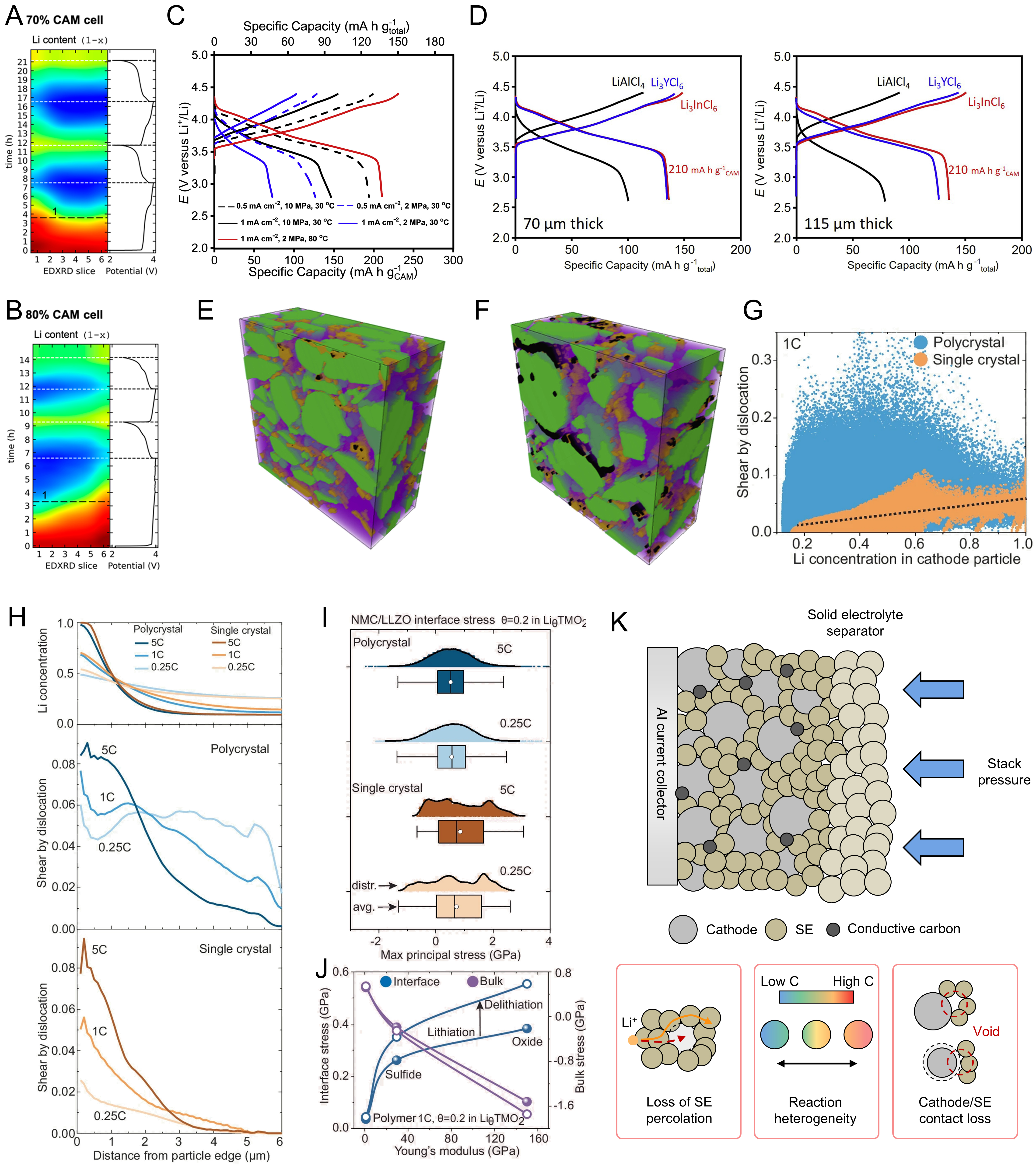
Figure 5. (A and B) Depth-dependent lithiation profiles of NMC111/Li6PS5Cl composite cathodes containing (A) 70 wt.% and (B) 80 wt.% CAM, obtained by high-energy depth-profiling XRD; (A and B) are reprinted with permission from Ref.[55] under a CC BY 4.0 license; (C) first-cycle capacity response of NMC83-based composite cathodes under different current-density, temperature, and stack-pressure conditions; (D) first-cycle specific-capacity profiles of 70 µm (left) and 115 µm (right) composite cathodes employing solid electrolytes with different ionic conductivities; (E) reconstructed 3D microstructure of the composite cathode before cycling; (F) reconstructed 3D microstructure of the composite cathode after 50 cycles; (C-F) are reprinted from Ref.[96] under a CC BY 4.0 license; (G and H) calculated distributions of (G) Li concentration and (H) dislocation-induced plastic shear in Ni-rich NCM composite cathodes; (I) CAM/SE interfacial stress during Li (de)intercalation; (J) dependence of interfacial stress on the mechanical properties of the SE; (G-J) are reprinted with permission from Ref.[97] under a CC BY 4.0 license; (K) schematic illustration of coupled transport, reaction, and chemo-mechanical degradation in thick ASSB composite cathodes. CAM: Cathode active material; NMC: nickel-manganese-cobalt; XRD: X-ray diffraction; SE: solid electrolyte; ASSB: all-solid-state battery.
Microstructural analysis further showed that increasing the CAM fraction changed the balance between the ion-conducting SE network and the electronically conducting CAM network. When the CAM fraction increased from 70 to 80 wt.%, the tortuosity factor of the Li6PS5Cl phase increased substantially, whereas that of the NMC phase decreased[55]. Thus, increasing the active-material fraction can improve the continuity of the electronically conducting CAM network while simultaneously reducing the volume fraction and connectivity of the ion-conducting SE phase. The resulting increase in SE tortuosity restricts Li+ transport and promotes more pronounced reaction heterogeneity. Accordingly, high CAM loading and electrochemical accessibility are not necessarily proportional in thick ASSB cathodes; rather, the energy-density benefit of increasing the active-material fraction must be balanced against the requirement for continuous solid-electrolyte percolation throughout the electrode thickness.
The accessible capacity of thick ASSB cathodes is additionally sensitive to the transport properties of the SE and the applied electrochemical and mechanical conditions. Gao et al. investigated composite cathodes composed of LiNi0.83Mn0.06Co0.11O2, Li3InCl6, and carbon nanofibers and showed that accessible cathode capacity was primarily limited by Li+ transport through the SE phase[96]. For a composite containing 65 wt.% CAM, 30 wt.% SE, and 5 wt.% carbon nanofibers, the influence of current density and stack pressure became particularly pronounced at 30 °C, whereas increasing the temperature to 80 °C substantially improved the accessible capacity under a stack pressure of 2 MPa [Figure 5C][96]. The dependence of capacity on SE conductivity became more pronounced as the electrode thickness increased. At 80 °C and 1 mA cm-2 under 2 MPa, increasing the composite-cathode thickness from 70 to 115 µm maintained a specific capacity of approximately 210 mAh g-1 based on the CAM mass, when the highly conducting Li3InCl6 was employed, enabling an areal capacity of approximately 5 mAh cm-2. In contrast, decreasing the SE conductivity substantially reduced the accessible capacity of the thicker electrode [Figure 5D][96]. These results show that the capacity benefit of electrode thickening in ASSBs can be realized only when the solid-ion-conducting network sustains sufficient Li+ transport under the imposed current density, temperature, and stack-pressure conditions.
In addition to restricting active-material utilization, the solid-solid nature of ASSB composite cathodes introduces progressive contact degradation during repeated cycling. Gao et al. showed that the composite cathode cycled between 2.6 and 4.4 V at 1 mA cm-2 and 80 °C under 2 MPa retained approximately 65% of its initial capacity after 50 cycles[96]. Three-dimensional reconstruction revealed substantial microstructural rearrangement and void formation after cycling, indicating degradation of the initially intimate interparticle contact [Figure 5E and F]. Increasing the stack pressure to 10 MPa improved the 50-cycle capacity retention to approximately 93%, consistent with improved preservation of particle contact. Alternatively, reducing the upper cut-off voltage from 4.4 to 4.2 V decreased the NMC volume change from approximately 6% to 2.5% and increased capacity retention from 65% to 94% at 2 MPa[96]. These observations demonstrate that repeated CAM volume changes can disrupt the solid-solid contact required for ion and electron transport, while stack pressure strongly affects the extent to which this contact is maintained during cycling.
The mechanical origin of this contact degradation can be further understood from grain-level chemo-mechanical behavior. Liu et al. developed a microstructure-sensitive chemo-mechanical model for Ni-rich nickel-cobalt-manganese (NCM) composite cathodes and showed that heterogeneous Li distribution, crystalline anisotropy, and state-of-charge-dependent lattice changes generate highly nonuniform stress and defect distributions within cathode particles[97]. Although this study was not designed specifically as a thick-electrode comparison, it provides a mechanistic basis for understanding how transport-induced reaction heterogeneity can be translated into particle- and interface-level degradation in ASSB composite cathodes. The calculated Li concentration and dislocation-induced plastic shear exhibited pronounced spatial heterogeneity, with Li-concentration gradients contributing to dislocation accumulation within the cathode particles [Figure 5G and H][97]. For polycrystalline particles, the random arrangement of primary particles further increased the heterogeneity of dislocation activity because the local strain response depended on crystallographic orientation and position within the secondary particle.
The same chemo-mechanical response also generated substantial stress at the CAM/SE interface. Liu et al. showed that anisotropic dimensional changes during Li (de)intercalation produced persistent tensile stress at the cathode/SE interface, providing a mechanical driving force for contact loss [Figure 5I][97]. Importantly, decreasing the discharge rate alone did not eliminate this interfacial tensile stress, indicating that contact degradation cannot be interpreted solely as a consequence of high-rate operation. The magnitude of the interfacial stress was also strongly dependent on the mechanical properties of the SE, and electrochemical cycling produced different stress states during lithiation and delithiation [Figure 5J][97]. These results indicate that mechanical degradation in ASSB composite cathodes is governed by the coupled response of CAM lattice changes, particle microstructure, and SE mechanical properties rather than by external operating conditions alone.
The accumulated crystal defects can further contribute to irreversible structural degradation. Liu et al. showed that dislocation-induced lattice strain modifies the local oxygen environment and can facilitate oxygen loss and transition-metal migration, thereby promoting structural degradation of Ni-rich layered cathodes[97]. Their analysis further showed that heterogeneous Li distribution and structural degradation can impede Li+ transport within the cathode particle, generating an additional kinetic capacity loss. Thus, reaction heterogeneity and mechanical degradation can form a self-reinforcing process: nonuniform Li+ transport generates local concentration and strain gradients, which promote crystal-defect formation and interfacial stress; the resulting structural degradation and contact loss subsequently reduce active transport pathways and further increase reaction heterogeneity.
Collectively, degradation in thick ASSB composite cathodes can be understood as a coupled consequence of solid-electrolyte percolation limitations, depth-dependent reaction heterogeneity, CAM volume change, and loss of solid-solid contact [Figure 5K]. Increasing electrode thickness or CAM fraction increases the transport demand placed on the ion-conducting SE network, and insufficient ionic connectivity results in spatially nonuniform active-material utilization. Repeated Li+ insertion and extraction simultaneously generate heterogeneous lattice strain and particle-scale volume changes, which can induce crystal defects, interfacial stress, void formation, and contact loss. These changes progressively increase ionic and interfacial resistance and reduce the electrochemically accessible fraction of the thick composite cathode. The severity of these coupled degradation processes is further affected by operating current density, temperature, stack pressure, voltage window, CAM fraction, and the mechanical properties of the SE. Consequently, the practical capacity of thick ASSB electrodes depends not only on active-material loading but also on the ability to maintain continuous solid-electrolyte percolation, solid-solid contact, and homogeneous electrochemical reactions during repeated cycling.
THICK ELECTRODE DESIGN STRATEGIES
Overview of design strategies
To address the coupled transport, reaction, and degradation mechanisms associated with thick electrodes, electrode design needs to extend beyond simply increasing active material loading. Restricted Li+ transport, insufficient electrolyte accessibility or solid-electrolyte percolation, discontinuous electronic pathways, and through-thickness reaction heterogeneity can prevent the additional active material from being fully utilized. Accordingly, thick-electrode design requires targeted regulation of ionic and electronic transport pathways to sustain electrochemical accessibility throughout the electrode thickness.
Representative approaches can be broadly categorized according to the primary limitation they address. Low-tortuosity architectures introduce more direct ion-transport pathways to improve through-plane ionic transport and electrolyte accessibility[98-100]. Multilayer and gradient electrodes spatially regulate composition, porosity, particle size, or conductive-agent distribution to mitigate through-thickness differences in transport and reaction kinetics[101-105]. Conductive-network engineering aims to maintain continuous electronic pathways and suppress local current concentration, particularly in high-loading and dry-processed electrodes[106-109]. In parallel, model- and diagnostics-guided approaches provide spatially resolved information on transport, reaction distribution, and active-material utilization, enabling the dominant bottleneck to be identified and the corresponding electrode architecture to be rationally optimized[110-115]. These representative strategies are schematically summarized in Figure 6 and discussed in detail in the following sections.
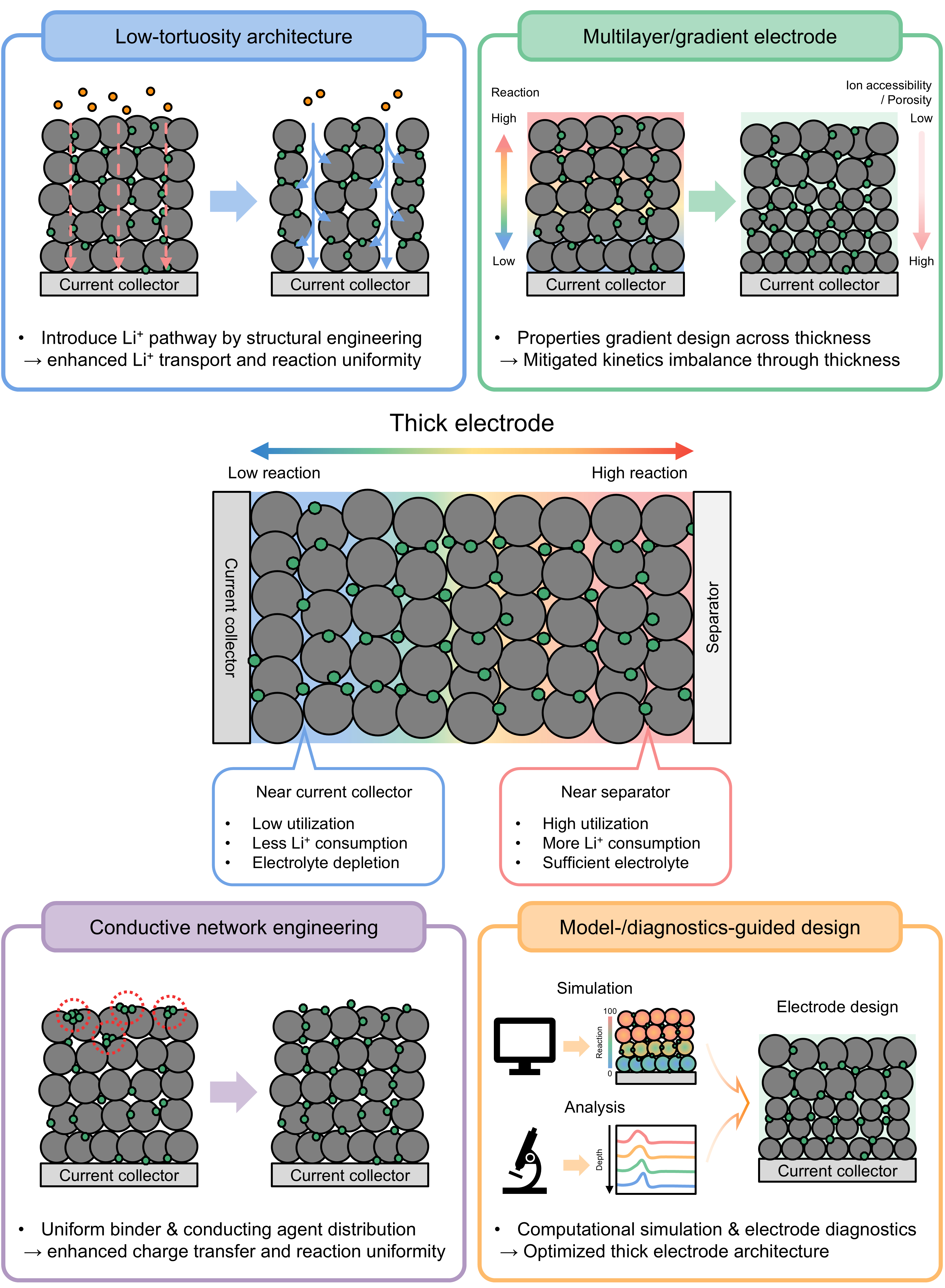
Figure 6. Schematic illustration of representative strategies for mitigating the technical limitations of thick electrodes.
Low-tortuosity architectures
Low-tortuosity architectures have been developed to address the Li+ transport limitations that become more pronounced in thick electrodes. In conventional slurry-cast electrodes, active material particles are randomly stacked and densely compacted during calendering, producing convoluted pore networks. As the electrode thickness increases, this tortuous microstructure not only elongates Li+ transport pathways but also suppresses electrolyte infiltration into the inner electrode region[40-47]. Consequently, the electrolyte-accessible reaction zone becomes spatially limited, leading to concentration polarization, delayed reaction kinetics, and incomplete active-material utilization under high-loading and high-current conditions. Wu et al. proposed a temporally shaped ultraviolet femtosecond laser strategy to fabricate low-tortuosity thick electrodes with high-density through-hole arrays[98]. The through-holes provide direct ion-transport pathways across the electrode thickness, facilitating electrolyte infiltration into the inner region of thick LiFePO4 electrodes [Figure 7A]. Unlike conventional pore-forming or templating methods, this laser-based post-treatment is compatible with calendered electrodes and minimizes active material loss, which is critical for preserving the energy-density advantage of thick electrodes. By controlling the laser wavelength and objective lens numerical aperture, the authors systematically regulated the aperture size and aspect ratio of the drilled holes [Figure 7B]. In particular, frequency-domain shaping from 800 to 400 nm enabled the formation of smaller through-holes, while maintaining sufficient focal depth for through-electrode drilling.
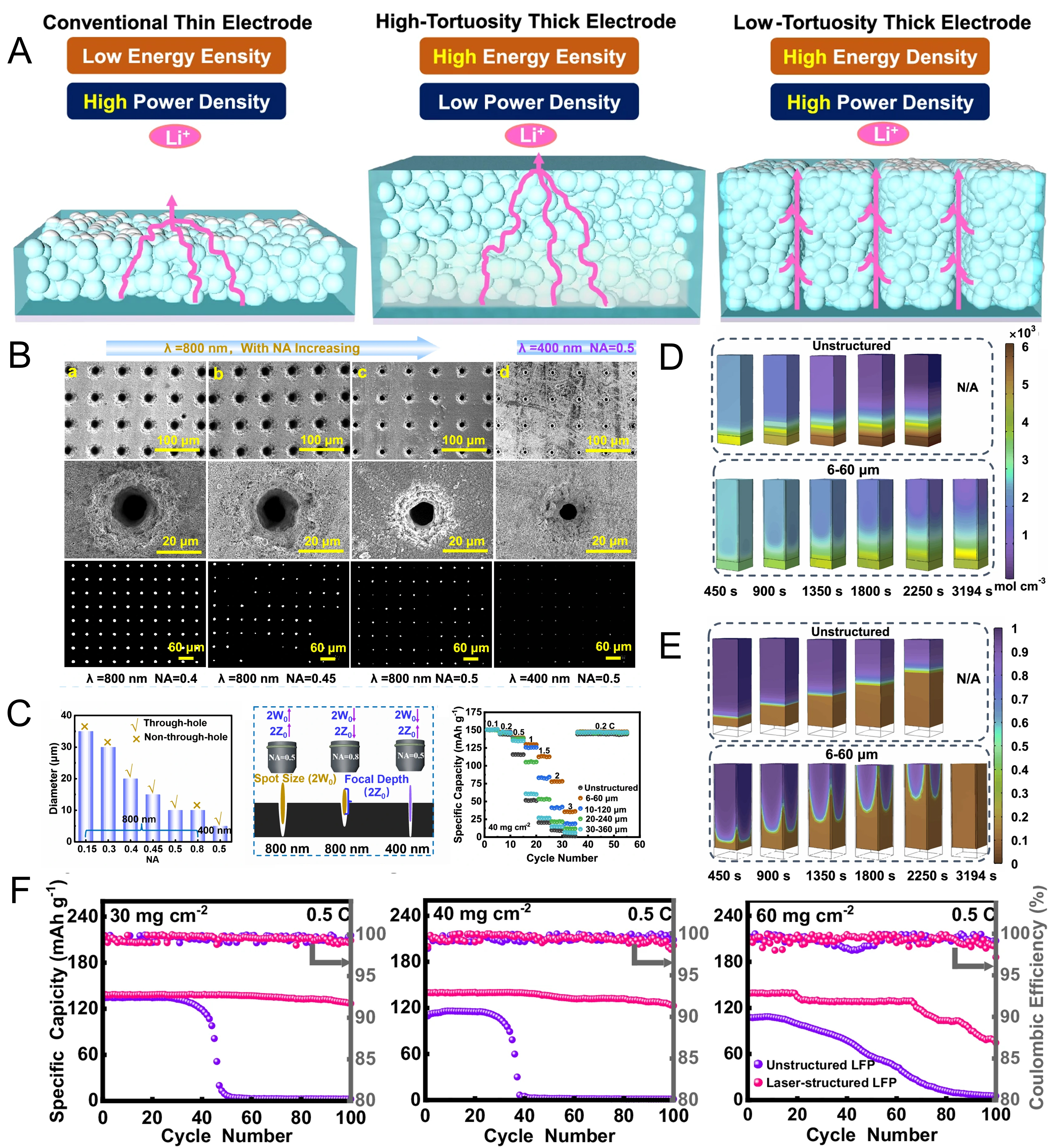
Figure 7. (A) Schematic illustration of conventional thin, high-tortuosity thick, and low-tortuosity thick electrodes; (B) SEM and backlight microscopy images showing micro-hole arrays created by femtosecond laser percussion drilling using objective lenses with different numerical apertures (NA = 0.4, 0.45, and 0.5) and different wavelengths (800 and 400 nm); (C) relationship between aperture size, NA, and wavelength (left), effects of NA and wavelength on the diameter and aspect ratio of laser-drilled holes (middle), and influence of hole size/distribution on rate capability for 6-60, 10-120, 20-240, and 30-360 μm configurations (right); (D) electrolyte salt concentration distribution; (E) electrode state-of-charge evolution over time for unstructured LFP and 6-60 μm structured LFP during 1C discharge; (F) cycling performance at 0.5C for different mass loadings (30, 40, and 60 mg cm-2); (A-F) are reprinted with permission from Ref.[98], under CC BY NC-ND license. SEM: Scanning electron microscopy; NA: numerical aperture.
The electrochemical benefit of this architecture was strongly dependent on the hole size and distribution. Among the examined configurations, the 6-60 µm structure, defined by a 6 µm hole diameter and 60 µm hole spacing, delivered the most favorable rate capability compared with larger and more sparsely distributed hole arrays, such as 10-120, 20-240, and 30-360 µm configurations [Figure 7C]. The superior rate capability of the 6-60 µm configuration can be attributed to its dense, small-diameter through-hole network, which shortens local ion-diffusion distances without causing substantial material loss. COMSOL simulations further supported this interpretation. In the unstructured thick electrode, electrolyte salt concentration was rapidly depleted near the bottom region during discharge, which can limit reaction progression before the entire electrode is fully utilized. In contrast, the laser-structured electrode maintained a more uniform electrolyte concentration profile and sustained a more homogeneous state-of-charge evolution throughout the electrode thickness [Figure 7D and E]. These improvements in ion accessibility were directly reflected in the electrochemical performance of thick electrodes. The laser-structured LiFePO4 electrodes exhibited reduced tortuosity, lower ionic resistance, improved rate capability, and higher capacity retention during cycling compared with unstructured electrodes[98]. Importantly, the advantage became more pronounced at higher mass loadings, where ion-transport limitation is typically dominant. Even under 30, 40, and 60 mg cm-2 loading conditions, the laser-structured electrodes retained higher discharge capacity during repeated cycling at 0.5C than their unstructured counterparts [Figure 7F]. The higher capacity retention of the laser-structured electrodes indicates that low-tortuosity architectures can mitigate the trade-off between high active material loading and sluggish ion transport by improving electrolyte infiltration, suppressing concentration polarization, and promoting more uniform electrochemical reactions.
Nevertheless, the effectiveness of low-tortuosity architectures depends on whether ionic transport is the dominant limitation under the applied electrode loading and operating conditions. The strong dependence of electrochemical performance on hole diameter and spacing in the study by Wu et al. indicates that simply introducing through-plane channels is insufficient; the channel geometry needs to balance shortened ion-transport pathways with preservation of the active-material fraction[98]. In particular, dense through-hole arrays can enhance electrolyte accessibility, whereas excessive or poorly optimized material removal would reduce the loading advantage that motivates thick-electrode design. From a manufacturing perspective, laser structuring offers the advantage of being applicable as a post-treatment to calendered electrodes and, in the optimized configuration reported by Wu et al., enables low material loss[98]. However, it introduces an additional processing step and requires precise control of the channel geometry across the electrode area, such that processing throughput, scalability, and compatibility with large-area manufacturing need to be considered together with the electrochemical benefit[36,37]. Low-tortuosity architectures are therefore most advantageous for high-loading electrodes in which through-plane ionic transport and electrolyte accessibility primarily limit active-material utilization, whereas additional design strategies may be required when electronic conduction or spatial reaction imbalance becomes comparably limiting.
Multilayer and gradient electrodes
Multilayer and gradient electrode architectures have been developed to address the position-dependent transport and reaction imbalance that becomes pronounced in thick electrodes. In homogeneous thick electrodes, Li+ transport, electrolyte accessibility, electronic conduction, and reaction kinetics are not uniformly distributed along the electrode thickness. The separator-facing region is readily supplied with electrolyte and Li+, whereas the current-collector-facing region is more vulnerable to delayed ion transport, electrolyte depletion, and incomplete active-material utilization. This mismatch generates concentration polarization and local reaction heterogeneity, particularly under fast-charging or high-rate operating conditions. Multilayer and gradient designs aim to mitigate these limitations by assigning different transport or reaction functions to different electrode regions. Kang et al. demonstrated this concept using dual-layered hybrid graphite anodes for fast-charging Li-ion batteries[90]. Instead of randomly blending natural graphite and synthetic graphite into a single-layer electrode, the authors fabricated sequentially coated dual-layer electrodes with different layer orders, denoted as single-layer electrode containing a 50:50 mixture of natural graphite and synthetic graphite (SLE-X), dual-layer electrode with natural graphite in the bottom layer and synthetic graphite in the top layer (DLE-NS), and dual-layer electrode with synthetic graphite in the bottom layer and natural graphite in the top layer (DLE-SN) [Figure 8A]. The cross-sectional focused ion beam-scanning electron microscopy (FIB-SEM) images confirmed that the proposed single-layer and dual-layer electrodes were successfully constructed with controlled through-thickness configurations. This configuration is relevant because the position of each graphite component determines how Li+ influx, electron transport, and interfacial reaction proceed during fast charging. To clarify how the dual-layer configuration modulates transport and resistance, the authors selectively measured the interfacial and bulk resistances of SLEs and DLEs using an electrode resistance measurement system [Figure 8B]. This analysis showed that the internal resistance of the electrode is not governed solely by the intrinsic properties of each graphite component, but also by its location within the electrode. In thick or fast-charging anodes, the separator-facing region experiences rapid Li+ supply and a high local reaction demand, whereas the current-collector-facing region must sustain charge transport over a longer distance. Therefore, arranging graphite components with appropriate kinetic properties at position-specific regions can reduce polarization and improve active-material utilization. The through-thickness electrolyte accessibility was further investigated using sodium laser-induced breakdown spectroscopy (Na-LIBS) depth profiling [Figure 8C]. Because Na+ from the electrolyte can act as a tracer for electrolyte infiltration, the depth profiles of relative Na+ counts provide information on how effectively the electrolyte reaches different regions of the electrode[90]. This diagnostic result is directly relevant to thick electrode design because limited electrolyte accessibility in the inner electrode region aggravates Li+ transport limitation and reaction nonuniformity. Thus, the Na-LIBS analysis supports the idea that sequential layer ordering can influence not only electronic and interfacial resistance but also the electrolyte-accessible reaction environment across the electrode thickness. The fast-charging behavior of the single- and dual-layer graphite electrodes was further examined through transient overpotential responses at 4C [Figure 8D]. The temporal overpotential evolution provides a direct indication of how rapidly polarization develops during charging. Compared with the single-layer electrode, the optimized dual-layer electrode showed a more favorable overpotential response, indicating that the sequential arrangement of graphite components can mitigate abrupt polarization buildup under fast-charging conditions[90]. This effect arises because the dual-layer design redistributes the local reaction burden along the electrode depth, rather than allowing the separator-facing region to dominate the charging reaction. The depth-dependent lithiation behavior was directly visualized by Li-LIBS-guided Li+ distribution maps after the first 4C charging [Figure 8E]. These maps revealed how Li+ was distributed within SLEs and DLEs immediately after fast charging. In conventional single-layer electrodes, fast charging tends to induce localized lithiation in the separator-facing region, which increases the risk of local overutilization and Li plating. In contrast, the optimized dual-layer electrode promoted a more balanced Li+ distribution across the electrode thickness, indicating that a larger fraction of the electrode participated in reversible lithiation[90]. This result demonstrates that dual-layer graphite design can alleviate depth-dependent reaction inhomogeneity by coordinating local kinetic properties with the spatial demand for Li+ transport.
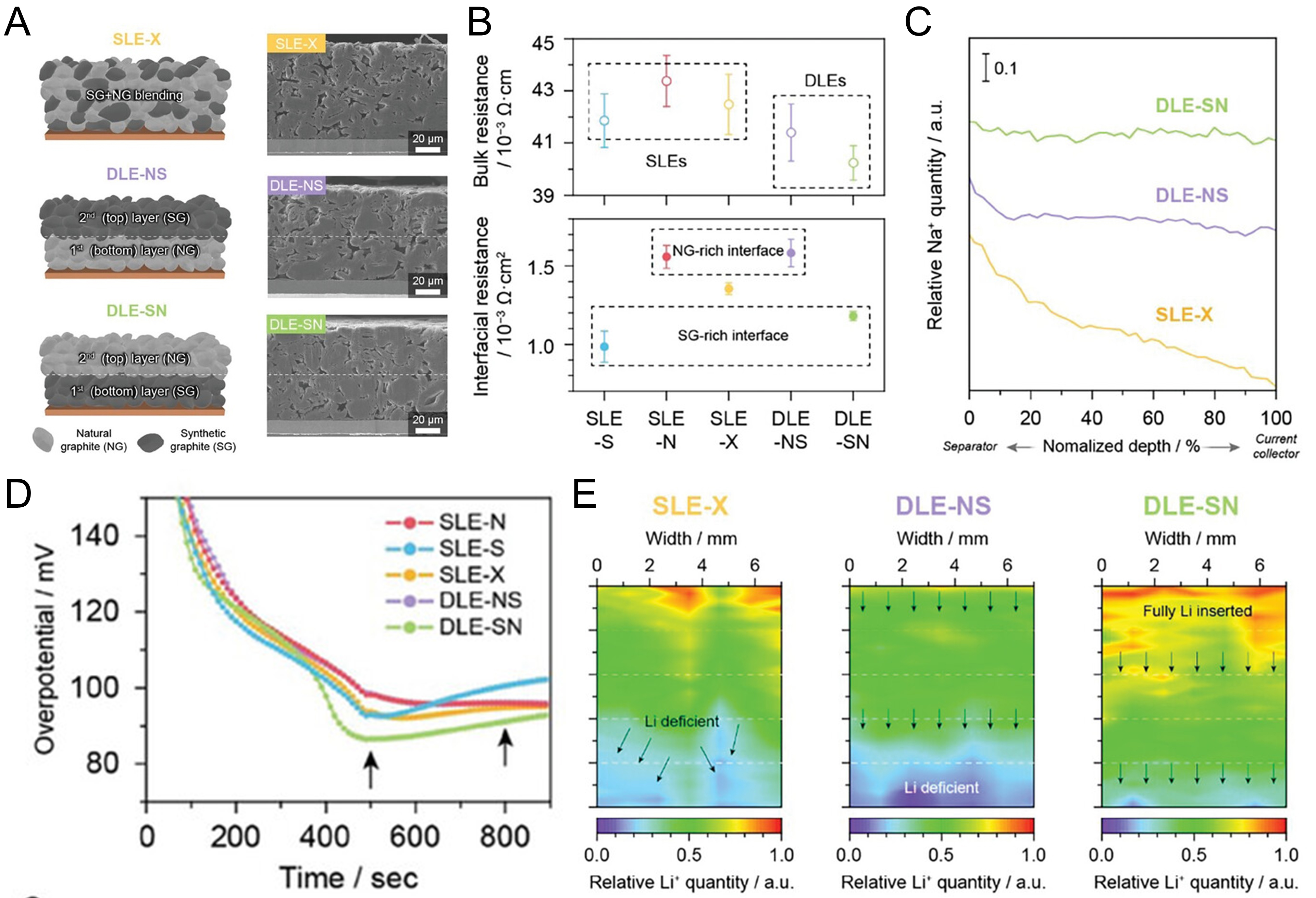
Figure 8. (A) Schematic illustration and FIB-SEM images of as-prepared SLE-X, DLE-NS, and DLE-SN hybrid anodes; (B) selective measurement of interface and bulk resistances of SLEs and DLEs using the electrode resistance measurement system; (C) depth profiles of relative sodium (Na+) counts during Na-LIBS; (D) transient overpotential responses of SLEs and DLEs within 15 min of charging at 4C; (E) Li+-LIBS-guided Li+ distribution maps obtained after the first 4C charge; (A-E) are reprinted with permission from Ref.[88], under CC BY 4.0 license. SLE-X: single-layer electrode containing a 50:50 mixture of natural graphite and synthetic graphite; DLE-NS: dual-layer electrode with natural graphite in the bottom layer and synthetic graphite in the top layer; DLE-SN: dual-layer electrode with synthetic graphite in the bottom layer and natural graphite in the top layer; SLE: single-layer electrode; DLE: dual-layer electrode; FIB: focused ion beam; SEM: scanning electron microscopy.
Chen et al. extended a similar design philosophy to high-loading NMC83 cathodes using a particle-size-gradient architecture composed of large and small active-material particles[102]. By appropriately arranging particles with different pore-forming and reaction characteristics, the optimized double-layer structure improved electrolyte accessibility and rate capability under high-loading conditions. These results demonstrate that particle-size-gradient design can mitigate concentration polarization by spatially coordinating electrolyte transport with particle-size-dependent reaction kinetics.
Multilayer and gradient electrodes can therefore be considered position-dependent architectures rather than simple stacked configurations. In thick anodes, dual-layer graphite designs can regulate Li+ distribution, electrolyte accessibility, overpotential evolution, and local active-material utilization during fast charging. In thick cathodes, particle-size gradients can spatially coordinate electrolyte transport and reaction kinetics. By matching electrode properties to the local electrochemical environment, multilayer and gradient architectures can mitigate concentration polarization, suppress localized overutilization, and improve active-material utilization in thick electrodes.
Nevertheless, the effectiveness of multilayer and gradient architectures depends strongly on how accurately the spatial distribution of electrode properties is matched to the local transport and reaction demand. The results of Kang et al. show that changing the sequence of the same graphite components substantially alters electrolyte accessibility, overpotential evolution, and Li+ distribution, indicating that the benefit arises from appropriate layer ordering rather than from multilayer construction itself[90]. Similarly, Chen et al. demonstrated that both the large-/small-particle sequence and the relative thickness of the two layers critically affect electrolyte infiltration and rate capability[102]. An insufficient large-particle layer cannot establish effective electrolyte diffusion pathways, whereas an excessive fraction limits the contribution of the fast-reacting small-particle region. These observations indicate that the optimal gradient is not universal but needs to be matched to electrode loading, operating current, and the dominant transport limitation.
From a manufacturing perspective, multilayer and gradient architectures can redistribute transport and reaction functions without necessarily relying on material removal; however, this benefit is accompanied by additional requirements for controlling layer sequence, composition, and thickness. Sequential fabrication can therefore increase processing complexity compared with conventional homogeneous electrodes, while deviations in layer thickness or composition over a large electrode area may reduce the intended spatial balance in transport and reaction kinetics[36]. Accordingly, the practical implementation of multilayer and gradient electrodes requires consideration of not only their electrochemical benefit but also fabrication complexity, reproducibility, and compatibility with scalable electrode manufacturing. Their greatest advantage lies in electrodes where the dominant limitation varies systematically along the thickness direction, whereas more homogeneous transport limitations may be addressed more efficiently by simpler architectural modifications.
Conductive network engineering
Conductive network engineering has emerged as an important strategy for mitigating charge-transport limitations in thick electrodes. As electrode thickness and areal capacity increase, electron pathways become longer and more susceptible to discontinuity, while Li+ transport is simultaneously constrained by tortuous pore networks and limited electrolyte accessibility. Under these conditions, electrochemical reactions can become spatially localized when conductive additives are not uniformly distributed throughout the electrode. This issue can be particularly pronounced in dry-processed electrodes, where the conductive network must be constructed through mechanical mixing and calendering without solvent-assisted dispersion. Therefore, controlling the morphology, dispersion, and connectivity of conductive additives is essential for achieving uniform reaction kinetics in thick electrodes. Min et al. addressed this challenge by mechanically unwinding pristine carbon nanotube aggregates into unwound carbon nanotubes (uCNTs), which were compared with Super P carbon (SPC) and pristine CNTs (pCNTs) as conductive additives in high-loading dry cathodes [Figure 9A][106]. The unwinding process converted entangled CNT bundles into extended one-dimensional conductive strands, thereby improving their ability to bridge adjacent active material particles and establish long-range electron pathways. The dry electrodes were fabricated through a solvent-free process involving powder mixing, dry sheet formation, calendering, and lamination onto an Al current collector [Figure 9B]. This process is relevant to thick electrode manufacturing because it enables high active material loading while avoiding solvent evaporation, binder migration, and drying-induced heterogeneity.
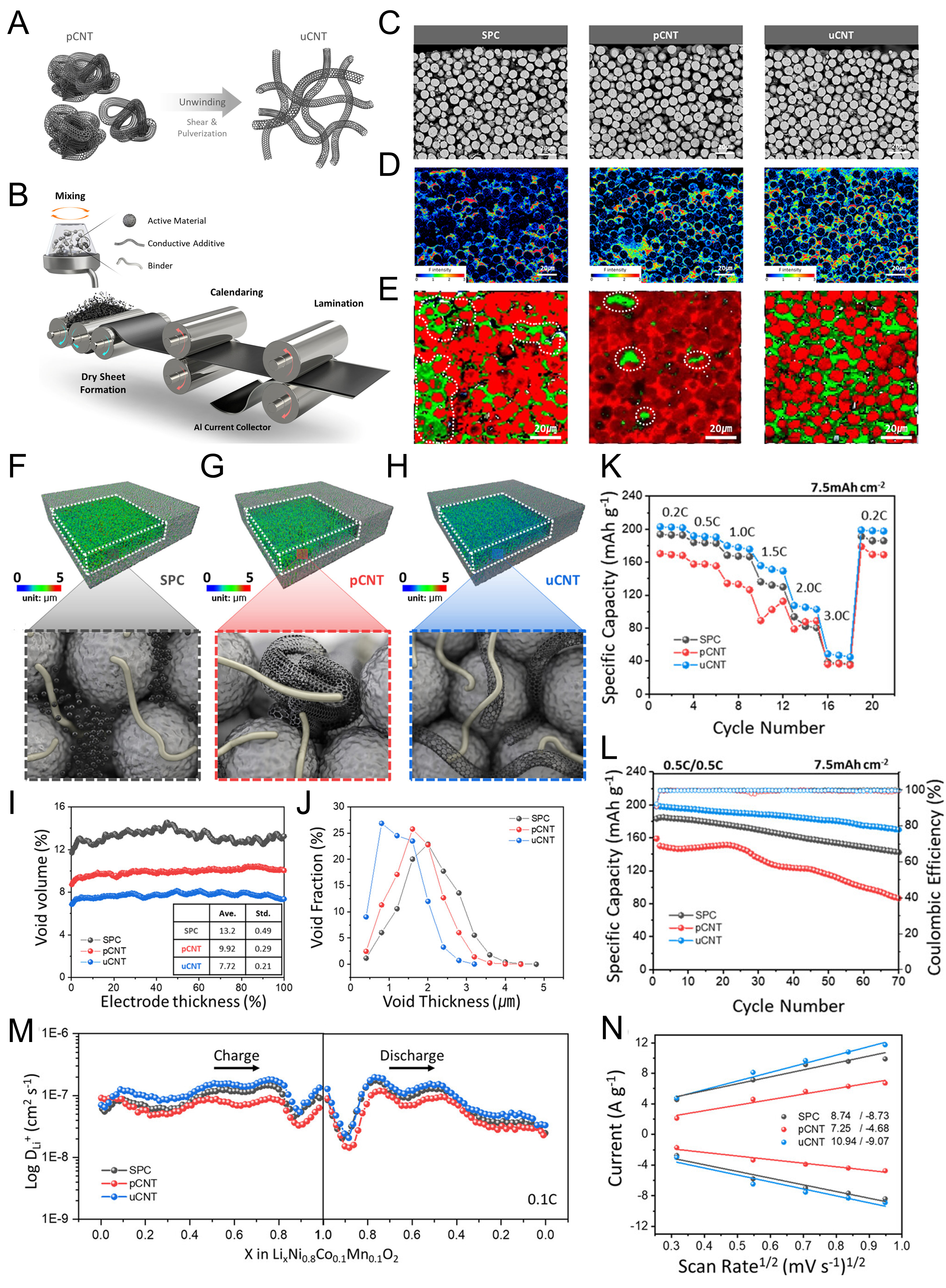
Figure 9. (A and B) Schematic illustration of (A) the unwinding process of entangled CNTs (left) into unwound CNTs (right), and (B) the preparation for fabricating the dry-processed cathode; (C-E) cross-sectional morphology and spatial distribution of binder and conductive networks in dry-processed electrodes; (C) cross-sectional SEM images of SPC, pCNT, and uCNT electrodes; (D) corresponding EPMA WDS elemental maps of F and (E) Raman maps of NCM (red) and carbon (green); (F-H) high-resolution XRM images of (F) SPC, (G) pCNT, and (H) uCNT electrodes; (I) void volume distribution across the electrode thickness obtained from XRM analysis; (J) void-thickness distributions of each electrode obtained from XRM datasets; (K-L) electrochemical performance of half-cells using SPC, pCNT, and uCNT electrodes at 7.5 mAh cm-2; (K) rate and (L) cycling performance; (M) Li+ diffusion coefficients (DLi+); (N) linear relationship between the peak current and the square root of the scan rate; (A-N) are reprinted with permission from Ref.[106] under a CC BY 4.0 license. pCNT: Pristine carbon nanotube; uCNT: unwound carbon nanotube; SPC: Super P carbon; SEM: scanning electron microscopy; EPMA: electron probe microanalysis; WDS: wavelength-dispersive spectroscopy; XRM: X-ray microscopy; NCM: nickel-cobalt-manganese.
The internal electrode morphology revealed that the conductive additive structure strongly governed the formation of electron-conduction pathways. Cross-sectional images showed that SPC-, pCNT-, and uCNT-based electrodes maintained dense electrode structures after dry processing [Figure 9C]. However, electron probe microanalysis with wavelength-dispersive spectroscopy (EPMA-WDS) elemental mapping and Raman mapping further revealed differences in the spatial distribution of the binder and conductive components [Figure 9D and E]. In the SPC electrode, conductive carbon existed as discrete point-like domains, which can limit continuous electronic percolation over long distances. In the pCNT electrode, CNT aggregation produced locally concentrated conductive regions and carbon-deficient domains. In contrast, the uCNT electrode exhibited a more homogeneous conductive network across the electrode cross-section, indicating that mechanical unwinding effectively suppressed CNT agglomeration and improved conductive additive connectivity. Three-dimensional reconstructed electrode structures further illustrated the effect of conductive network morphology [Figure 9F-H]. The SPC electrode showed discontinuous carbon domains between active material particles, whereas the pCNT electrode contained bulky CNT clusters that generated nonuniform conductive pathways. By comparison, the uCNT electrode displayed extended CNT strands distributed between particles, forming a more continuous conductive framework throughout the electrode. This feature is particularly important in thick electrodes because electron transport needs to be maintained not only in the current-collector-facing region but also in the separator-facing region. A spatially uniform conductive network can therefore reduce electronic bottlenecks, alleviate local current concentration, and promote more homogeneous active-material utilization. The conductive additive morphology also influenced the void structure of the dry electrodes. The uCNT electrode exhibited a lower void volume and a narrower void-thickness distribution than the SPC and pCNT electrodes [Figure 9I and J]. Such a more uniform void architecture reflects the role of unwound CNTs in homogenizing electrode packing and suppressing large void formation. In thick electrodes, this structural uniformity is critical because large and unevenly distributed voids can interrupt electronic percolation and create nonuniform electrolyte-filled pathways, thereby contributing to local reaction imbalance. The uCNT network therefore improves the structural uniformity of the dry electrode while maintaining interconnected charge-transport pathways.
The electrochemical benefit of the uCNT-based conductive network was demonstrated under a high areal capacity of 7.5 mAh cm-2. In rate capability tests, the uCNT electrode delivered higher specific capacity than the SPC and pCNT electrodes over a wide range of current densities, especially under high-rate operation [Figure 9K]. During repeated cycling at 0.5C/0.5C, the uCNT electrode also maintained higher capacity retention and more stable Coulombic efficiency than the other electrodes [Figure 9L]. By forming a homogeneous one-dimensional conductive network, the dry cathode maintained more efficient electronic pathways and reduced kinetic constraints under high-loading conditions. The improved electrochemical kinetics were further supported by apparent Li+ transport and charge-transfer analyses. The uCNT electrode exhibited more favorable apparent Li+ transport behavior during both charge and discharge compared with the SPC and pCNT electrodes [Figure 9M]. In addition, the scan-rate-dependent current response showed a larger slope for the uCNT electrode, indicating enhanced charge-transfer characteristics and faster electrochemical response [Figure 9N]. These kinetic improvements are consistent with the structural observations: the unwound CNT network forms continuous electron pathways, improves conductive additive dispersion, reduces isolated reaction domains, and supports more uniform electrochemical reactions within the thick electrode. The key design variable is therefore not only the total conductive-additive content but also the continuity and spatial uniformity of the conductive framework with minimal inactive-component penalty. By transforming aggregated CNTs into extended conductive strands, uCNTs regulate both conductive-network connectivity and void architecture, thereby improving apparent Li+ transport kinetics and sustaining higher capacity retention under high areal capacity conditions. Therefore, conductive network engineering provides a practical route to mitigate transport-induced polarization and improve the electrochemical utilization of thick electrodes while preserving the energy-density advantage of high active material loading. At the same time, conductive-network design should preserve sufficient pore connectivity for electrolyte infiltration and through-plane Li+ transport, because excessive densification could compromise ionic accessibility in thick electrodes.
The effectiveness of conductive-network engineering therefore depends on balancing electronic connectivity with ionic accessibility rather than maximizing electronic conductivity alone. The comparison among SPC, pCNT, and uCNT electrodes by Min et al. demonstrates that increasing the dimensionality of a conductive additive is insufficient when the additive remains locally aggregated; instead, a continuous and spatially homogeneous conductive network is required to maintain electron transport over the extended length scale of a thick electrode[106]. Importantly, conductive additives also modify electrode packing and void structure, meaning that improvement in electronic percolation can simultaneously alter electrolyte-accessible pathways. An excessively dense or locally concentrated conductive network may therefore improve electronic conduction while restricting pore connectivity, whereas insufficient conductive-additive connectivity can generate electronically isolated active-material domains. Conductive-network design is consequently most effective when electronic discontinuity or local current concentration contributes substantially to the utilization loss, but it cannot independently resolve severe through-plane ionic transport limitations.
The manufacturing route also determines how effectively such conductive networks can be realized in thick electrodes. The uCNT architecture examined by Min et al. is particularly relevant to solvent-free electrode processing, where conductive additives and binders need to form continuous networks through mechanical mixing and calendering without solvent-assisted dispersion[106]. More broadly, Zheng et al. identified solvent-free approaches, including dry spraying, dry powder coating, powder extrusion molding, and 3D printing, as alternative routes for producing thick electrodes without the drying-induced stresses associated with conventional slurry casting[116]. These approaches can alleviate drying-related cracking and eliminate solvent-removal processes, although the resulting electrode performance remains dependent on how uniformly active materials, binders, and conductive components are distributed within the thick electrode[116]. Thus, solvent-free processing should be considered together with conductive-network formation rather than solely as a means of increasing electrode thickness.
A complementary approach is to directly integrate active materials with three-dimensional conductive scaffolds. Kang et al. demonstrated a self-standing CuCoNi-oxide nanowire array grown on Cu foam without conventional binders or conductive additives, illustrating that electronic connectivity and mechanical support can be incorporated directly into the electrode architecture[117]. Although this study was not specifically designed for high-loading thick electrodes, such self-standing structures provide a complementary design concept for reducing inactive components while maintaining continuous electronic pathways.
Overall, conductive-network engineering offers a comparatively direct means of improving electron transport without intentionally removing active material or introducing multiple compositionally distinct electrode layers. Its practical benefit, however, depends on simultaneously maintaining low inactive-component content, homogeneous conductive-additive dispersion, sufficient pore connectivity, and electrode density. The strategy is therefore complementary to low-tortuosity and gradient architectures rather than interchangeable with them: conductive-network engineering primarily addresses electronic percolation and local current distribution, whereas severe ionic transport or through-thickness reaction imbalance may require additional architectural control.
Model- and diagnostics-guided design
Model- and diagnostics-guided design has become an important approach for understanding and optimizing thick electrodes, because transport limitation and reaction heterogeneity are difficult to fully interpret from cell-level electrochemical curves alone. Although discharge profiles, rate capability, and capacity retention provide macroscopic indicators of electrode performance, they do not directly reveal where the reaction occurs, which region becomes underutilized, or how local Li+ transport is restricted within the electrode. Therefore, microstructure-resolved modeling and operando diagnostic techniques are increasingly used to connect electrode architecture with spatial reaction behavior, enabling more rational design of thick electrodes.
Lu et al. demonstrated the importance of microstructure-resolved modeling by comparing single-crystal and polycrystalline NMC811 electrodes[110]. Experimental discharge profiles were combined with three-dimensional simulations to predict rate-dependent performance, and the calculated curves showed good agreement with the measured electrochemical behavior [Figure 10A]. This agreement indicates that microstructure-resolved modeling can capture the key transport and reaction processes governing thick electrode performance. More importantly, the model visualized the internal state of lithiation, electrolyte concentration, and charge-transfer current density at 65% depth of discharge under 3C operation [Figure 10B-D]. These spatial maps revealed that the reaction in thick NMC811 electrodes can be highly nonuniform and is governed by the coupled effects of liquid-phase transport, solid-state diffusion, and local particle morphology. The modeling results further showed that different electrode microstructures generate different utilization patterns. In single-crystal electrodes, smaller and more uniform particles promoted more homogeneous lithiation, whereas polycrystalline electrodes contained large particles that were more likely to be underutilized during high-rate discharge. The analysis of individual particle C-rate and particle-volume fraction across the electrode thickness clarified that local reaction demand is not evenly distributed but varies depending on the distance from the separator, particle size, and local electrolyte environment [Figure 10E]. The particle-level C-rate analysis further links local utilization behavior to specific microstructural variables, including particle size distribution, porosity, electrode thickness, and spatial particle arrangement. These parameters therefore serve as design targets for mitigating concentration polarization and improving active-material utilization. Thus, microstructure-resolved modeling provides a quantitative basis for designing gradient particle distributions or position-dependent electrode architectures, rather than relying on empirical trial-and-error optimization. Complementary to modeling, operando diagnostics provide direct experimental evidence of reaction heterogeneity in working thick electrodes.
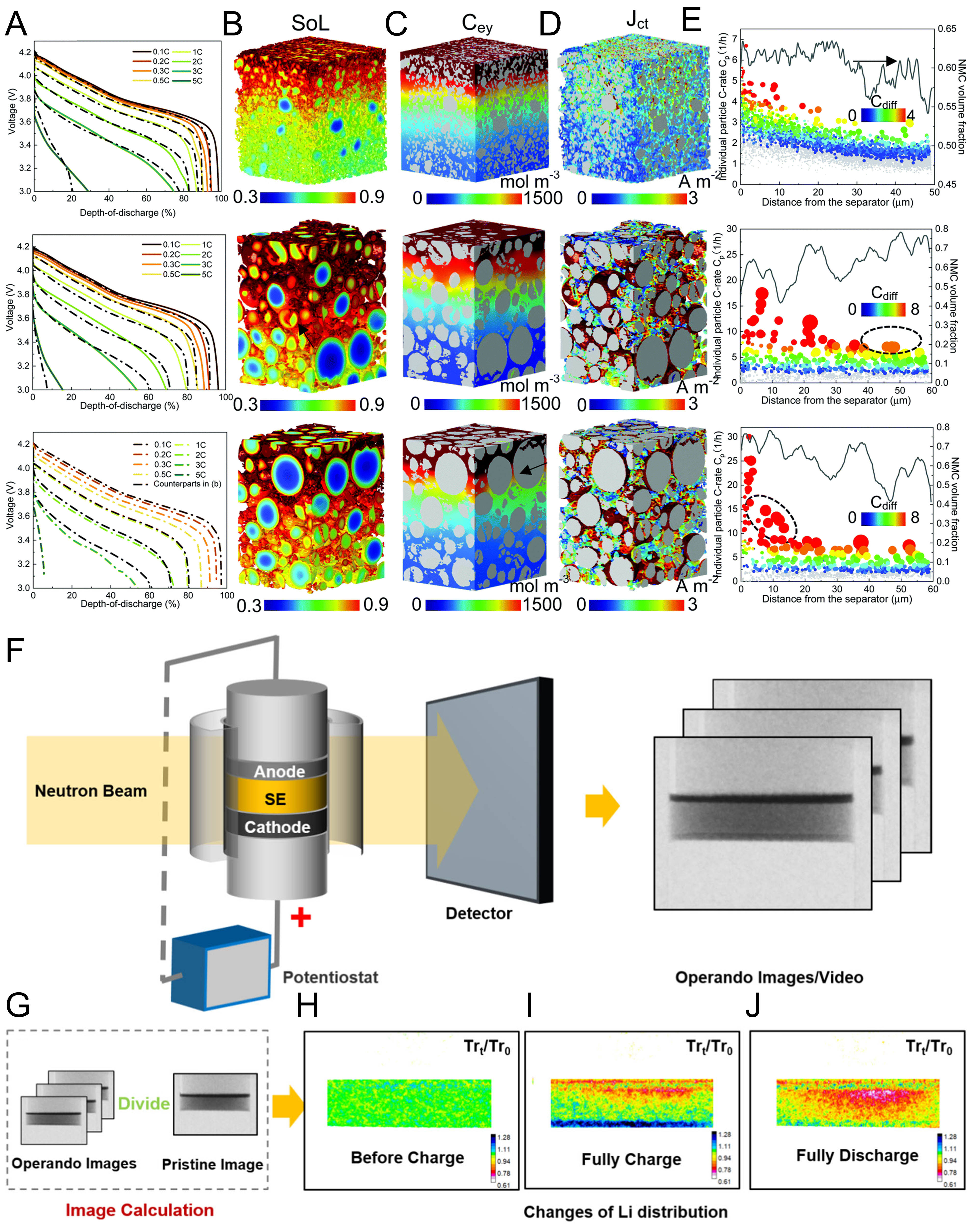
Figure 10. (A) Comparison of rate capability of SC, PC and reverse PC NCM811 electrodes by a combined analysis of experiment and modeling; (B) state of lithiation (SOL), (C) electrolyte concentration (Cey), and (D) charge-transfer current density (Jct) distribution at 65% depth of discharge (DOD); (E) actual C-rate of individual particles (Cp) shown alongside the volume fraction of the NMC particles (lines) across the electrode thickness; (A-E) are reprinted with permission from Ref.[110] under a CC BY 3.0 license; (F) schematic illustration of the experimental setup of operando neutron imaging; (G) schematic illustration of the image calculation process; (H-J) the results at different states; (H) before charge, (I) fully charged, and (J) fully discharged; (F-J) are reprinted with permission from Ref.[111], under CC BY NC-ND license. SE: Solid electrolyte; SC: single-crystal; PC: polycrystalline; NCM: nickel-cobalt-manganese; NMC: nickel-manganese-cobalt.
Ji et al. employed operando neutron imaging to visualize Li distribution in a high-mass-loading NMC811 composite cathode for all-solid-state batteries (33 mg cm-2, 5.0 mAh cm-2, approximately 180 μm thick)[111]. In this diagnostic configuration, the neutron beam passed through the operando cell composed of an anode, SE, and cathode, and the detector recorded transmission images during electrochemical operation [Figure 10F]. Because Li has strong neutron contrast, changes in neutron transmission can be converted into spatial information on Li distribution. The pristine image was used as a reference, and operando images collected during charge and discharge were processed to visualize changes in Li distribution within the thick cathode [Figure 10G]. The resulting neutron images directly showed the evolution of reaction heterogeneity during cycling. Before charging, the Li distribution was relatively uniform throughout the cathode [Figure 10H]. At the fully charged state, a pronounced spatial gradient appeared, indicating preferential delithiation in the solid-electrolyte-facing region and delayed reaction toward the current-collector-facing region [Figure 10I]. After full discharge, the Li distribution did not fully recover to a homogeneous state, showing that reaction nonuniformity persisted during the subsequent lithiation process [Figure 10J]. These observations demonstrate that high-mass-loading cathodes can exhibit position-dependent reaction kinetics, where the solid-electrolyte-facing region reacts preferentially while the current-collector-facing region remains kinetically delayed. More importantly, the neutron-imaging study translated this diagnostic insight into an electrode design principle. Ji et al. identified that, in addition to tortuosity, the mismatch between nonuniform Li+ flux generated by Faradaic reactions and the uniform distribution of the ion conductor in a conventional composite cathode creates an additional ion-transfer obstacle[111]. This point is particularly relevant to ASSB composite cathodes, where Li+ transport depends on continuous solid-ion-conductor percolation rather than liquid-electrolyte infiltration alone. Based on this observation, they designed a catholyte concentration gradient to match the local Li+ flux along the electrode thickness. This diagnostics-guided design improved rate capability even under high mass loading and enabled high areal capacity in ultra-high-loading cathodes. Therefore, operando diagnostics do not merely verify degradation phenomena; they provide spatially resolved information that can be directly converted into electrode architecture design.
Model- and diagnostics-guided approaches provide a quantitative basis for translating thick-electrode concepts into practical designs. Microstructure-resolved simulations clarify how particle morphology, porosity, and electrode thickness shape local reaction heterogeneity, whereas operando imaging captures Li redistribution and through-thickness reaction gradients during operation. Their combined use shifts thick-electrode optimization from nominal mass loading to position-dependent transport, reaction, and utilization behavior. These spatially resolved descriptors make it possible to evaluate whether a high-loading electrode can deliver achievable areal capacity at relevant current densities while maintaining a sufficient fraction of its designed capacity.
Model- and diagnostics-guided approaches therefore differ from structural strategies such as low-tortuosity, gradient, or conductive-network architectures because they do not directly modify the electrode. Instead, their primary role is to identify the dominant transport or reaction bottleneck and guide the selection and optimization of an appropriate electrode architecture. Their effectiveness depends on reliable model parameters and representative experimental conditions, but their combined use can reduce empirical optimization and help minimize the gap between designed and achievable areal capacity in thick electrodes.
Comparative assessment and strategy integration
The design strategies discussed above address distinct but interconnected limitations of thick electrodes, and their relative effectiveness therefore depends on the dominant bottleneck under a given electrode loading and operating condition. Low-tortuosity architectures are particularly effective when through-plane ionic transport or electrolyte accessibility limits active-material utilization, whereas multilayer and gradient designs are advantageous when the transport and reaction requirements vary systematically along the electrode thickness[98-105]. Conductive-network engineering is more directly suited to electrodes in which electronic discontinuity or local current concentration contributes substantially to utilization loss[106-109]. Model- and diagnostics-guided approaches, rather than acting as independent structural modifications, provide a means of determining which limitation governs the observed performance and thereby guide the selection and optimization of the appropriate architecture[110,111].
These strategies also involve different practical trade-offs. Low-tortuosity architectures can substantially shorten ionic transport pathways, but channel formation may introduce additional processing steps and, depending on the fabrication method, active-material loss. Multilayer and gradient electrodes can redistribute local reaction kinetics without intentionally removing active material, but require precise control of layer sequence, composition, and thickness, which increases manufacturing complexity. Conductive-network engineering can improve electronic percolation with a relatively small inactive-component fraction, although excessive densification or poorly controlled conductive-additive distribution can compromise pore connectivity and ionic accessibility. Thus, electrochemical improvement should be considered together with active-material fraction, electrode density, process complexity, reproducibility, and manufacturing throughput when evaluating the practical value of each strategy.
Importantly, the increasing coupling of ionic transport, electronic conduction, and reaction heterogeneity at high electrode loading suggests that a single architectural modification may not always be sufficient. Complementary strategies can be integrated when multiple transport limitations coexist. For example, low-tortuosity pathways can improve through-thickness Li+ transport, while a spatial gradient can redistribute local reaction demand within the newly accessible electrode volume. Similarly, conductive-network engineering can preserve electronic connectivity in regions made electrochemically accessible by ionic-transport-oriented architectures. Such integration, however, is beneficial only when the additional architectural complexity provides a measurable gain in achievable areal capacity and capacity utilization. Therefore, the rational design of thick electrodes should focus on identifying the dominant bottleneck first and introducing only the structural complexity required to overcome that limitation, rather than maximizing architectural complexity itself. From a cost perspective, the electrochemical benefit of advanced electrode architectures should also be weighed against the additional equipment, processing steps, and quality-control requirements associated with laser structuring, multilayer fabrication, or other architecturally complex manufacturing routes.
PRACTICAL DESIGN AND EVALUATION OF THICK ELECTRODES
Cell-level and manufacturing considerations
The practical benefit of thick electrodes needs to be evaluated at the cell level rather than from electrode loading alone. Increasing electrode thickness reduces the relative contribution of inactive components, including current collectors and separators, and can therefore increase cell-level energy density while reducing the number of electrode sheets required for a given cell capacity. However, this advantage is maintained only when the additional active material remains electrochemically accessible under the intended operating conditions. Singh et al. demonstrated this trade-off using NMC/graphite full cells with approximately 70 and 320 µm thick electrodes[118]. The thick-electrode cells exhibited a 19% higher volumetric energy density at C/5, whereas their performance deteriorated substantially at C/2 because of increased kinetic limitations. Thus, increasing electrode thickness can provide a clear cell-level energy benefit, but this advantage progressively diminishes when transport limitations prevent the additional active material from contributing to the delivered capacity.
Cell-level performance in liquid-electrolyte LIBs is also determined by parameters that are not captured by electrode thickness or mass loading alone. Electrode density and porosity determine the balance between volumetric energy density and ionic accessibility, while the active-material fraction needs to be balanced against sufficient conductive additive and binder contents. Cathode-anode capacity balance is similarly important because the influence of the N/P ratio depends on electrode thickness, mass loading, areal capacity, and operating rate[94]. Electrolyte amount and separator thickness and properties provide additional constraints: excess electrolyte can facilitate wetting and partially alleviate transport limitations in laboratory cells, but it also increases inactive mass and can obscure electrolyte-accessibility limitations that become important under practical conditions[119].
Electrode area and cell format constitute additional scaling parameters because electrochemical behavior observed in small-area coin cells does not necessarily translate directly to larger-format cells. Son et al. systematically compared NCA/graphite full cells using the same electrode materials, electrolyte, and electrode-coating parameters across ≈ 7 mAh coin cells and pouch cells with capacities ranging from 24 to approximately 1,000 mAh[120]. The cathode and anode loadings were maintained at 22.8 and 13.1 mg cm-2, respectively, with an N/P ratio of 1.1, thereby enabling the effect of cell configuration and scale to be examined under practically relevant electrode-loading conditions. Although the initial Coulombic efficiencies and low-rate voltage profiles were comparable among the different cell formats, substantial differences emerged in their internal resistance, rate capability, and long-term cycling behavior. The absolute cell resistance progressively decreased with increasing electrode area and pouch-cell capacity, and the pouch cells exhibited better rate capability than the coin cells despite using the same electrode chemistry[120]. In addition, the coin cells showed faster capacity fading and evidence of Li plating on the graphite anode during prolonged cycling, whereas the corresponding pouch-cell anodes maintained comparatively cleaner surfaces[120]. These observations demonstrate that cell hardware, electrode area, and stacking configuration can alter the apparent polarization and degradation behavior even when the intrinsic electrode formulation is unchanged. Therefore, electrochemical performance obtained from small-area cells should not be interpreted as a cell-format-independent property of a thick electrode. Although direct systematic comparisons involving cylindrical cells remain relatively limited, practical validation of thick electrodes should progressively extend from small-area laboratory cells to representative electrode areas, multilayer configurations, and application-relevant cell formats while maintaining comparable electrode loading and operating conditions.
ASSBs introduce a different set of cell-level constraints because the solid electrolyte serves as both the ion-conducting phase within the composite cathode and the separator between the electrodes. Increasing the CAM fraction can improve cathode-level energy density but simultaneously reduces the solid-electrolyte fraction available for continuous ionic percolation, creating a direct trade-off between active-material content and electrochemical utilization. Similarly, reducing the thickness of the solid-electrolyte separator lowers inactive mass and ionic resistance but increases the requirements for mechanical integrity and reliable cell fabrication. External pressure constitutes another practical design variable that is largely absent from conventional LIB evaluation. Fabrication pressure determines the initial densification and interparticle contact of the composite electrode, whereas operating stack pressure helps maintain solid-solid contact during repeated cycling[96]. Although increased pressure can improve electrochemical utilization and cycling stability, practical ASSBs need to achieve high areal capacity under moderate pressure because pressure-maintaining hardware introduces additional complexity and reduces the cell- or pack-level advantage expected from the solid-state architecture. Accordingly, thick ASSB electrodes should be evaluated together with CAM/solid-electrolyte ratio, solid-electrolyte separator thickness, anode excess, and fabrication and operating pressures rather than from cathode loading alone.
Manufacturing feasibility imposes a further boundary on the practically useful electrode thickness. In conventional slurry-based processing, increasing coating thickness intensifies drying-induced capillary stress and increases the susceptibility to cracking or delamination, defining a mechanical limitation represented by the critical cracking thickness (CCT)[116,121]. Importantly, mechanical integrity and electrochemical accessibility are not independent in thick electrodes. Cracking, delamination, and insufficient binder-mediated adhesion can disrupt continuous ionic and electronic transport pathways, thereby increasing local polarization and further aggravating reaction heterogeneity[121]. Even when mechanically stable thick electrodes can be fabricated, their electrochemical benefit remains constrained by the limited penetration depth (LPD) associated with ion transport through the electrode. These two limitations emphasize that practical electrode thickness needs to satisfy both manufacturing stability and electrochemical accessibility. Solvent-free processing can circumvent solvent-removal and drying-related limitations, whereas advanced architectures such as laser-structured or multilayer electrodes can improve transport and utilization, but these approaches introduce their own requirements for material distribution, process control, and manufacturing throughput. Therefore, scalable thick-electrode design requires a balance among active-material loading, electrode density, transport accessibility, mechanical integrity, and processing complexity rather than maximization of electrode thickness alone.
Capacity-utilization-based evaluation framework
Increasing electrode loading does not necessarily result in a proportional increase in practically accessible capacity. As discussed throughout this Review, transport limitations, reaction heterogeneity, and interfacial degradation can leave a substantial fraction of the loaded active material incompletely utilized, particularly as electrode thickness and operating current density increase. Therefore, designed areal capacity alone does not fully represent the electrochemical benefit of a thick electrode. A more informative evaluation requires consideration of how much of the designed capacity can actually be delivered under a specified operating condition.
In this Review, designed areal capacity (Qdesign) is defined as the areal capacity expected from the active-material loading before accounting for utilization losses arising from electrode-level transport and reaction limitations. When a designed, nominal, or theoretical areal capacity is explicitly adopted in the original publication as the reference capacity of the evaluated electrode, the reported value is used directly and its basis is identified in Supplementary Table 1. Otherwise, Qdesign is estimated as:
where mAM is the active-material loading (g cm-2) and qref is the reference reversible specific capacity (mAh g-1) of the corresponding active material under conditions in which electrode-level transport limitations are minimized. When available, qref is taken from a thin or reference electrode of the same active material measured within a comparable voltage window and temperature, preferably under a low-rate condition. If such a reference electrode is not provided, the reversible specific capacity obtained at the lowest reported current density for the corresponding material in the same study is used. The basis used to determine Qdesign for each literature entry is explicitly identified in Table S1 because theoretical, nominal, and experimentally referenced capacities can produce different values of Qdesign.
Achievable areal capacity (Qachievable) is defined as the experimentally delivered areal capacity under the specified electrochemical condition. Capacity utilization is then expressed as:
This parameter describes the fraction of the designed electrode capacity that remains electrochemically accessible under a specified operating condition, rather than simply the amount of active material incorporated into the electrode. Importantly, capacity utilization should not be regarded as an intrinsic property of an electrode because Qachievable depends strongly on operating current density, voltage window, temperature, cycle number, and cell configuration. For ASSBs, stack pressure and composite-cathode configuration constitute additional variables because solid-electrolyte percolation and solid-solid contact directly affect accessible capacity.
To enable a consistent literature comparison, the dataset used in Figure 11 was constructed using matched electrode and operating conditions. For each entry, Qdesign was assigned to the same electrode configuration used to determine Qachievable, while Qachievable and operating current density were obtained from the same electrochemical operating point. Operating current density was taken directly from the original publication when reported in mA cm-2; when only C-rate was provided, it was converted only when the corresponding capacity or current basis was explicitly defined. Table S1 summarizes Qdesign, Qachievable, operating current density, capacity utilization, the corresponding cell system and representative testing condition, and the basis used to determine Qdesign. Additional condition-dependent variables, including voltage window, temperature, cycle or test state, and stack pressure, were considered when interpreting the reported capacity utilization but are not intended to be exhaustively tabulated. To minimize ambiguity, the principal comparison was restricted to literature entries for which Qdesign, Qachievable, and operating current density could be obtained directly or derived through transparent calculations without combining unmatched electrode loadings or operating conditions[38,96,98,101,102,111,122-125].
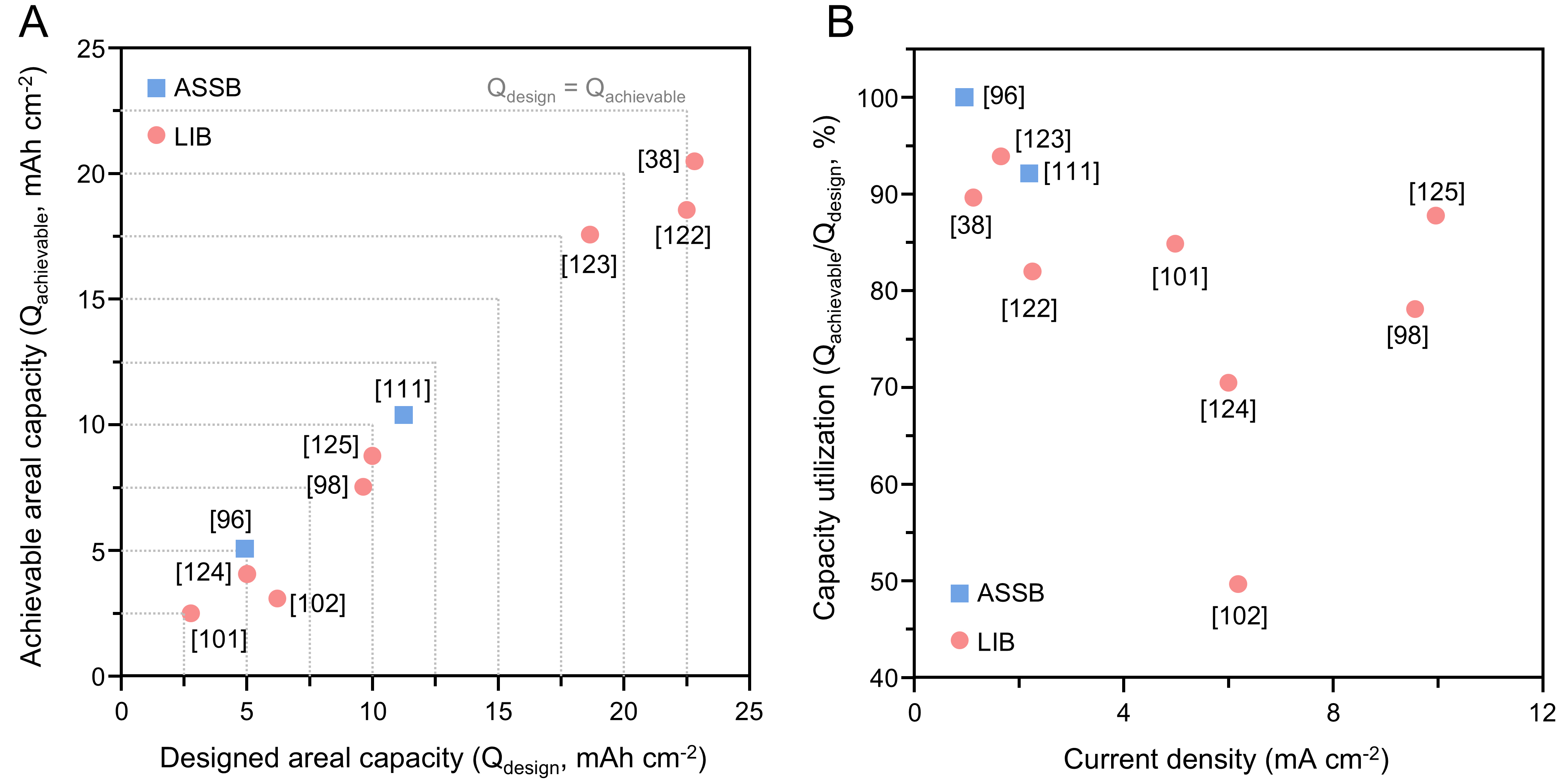
Figure 11. Capacity-utilization-based evaluation of representative thick electrodes. (A) Designed versus achievable areal capacity. (B) Capacity utilization as a function of operating current density. Representative testing conditions and calculation bases are summarized in Supplementary Table 1. ASSB: All-solid-state battery; LIB: Li-ion battery.
Figure 11A compares Qdesign and Qachievable for the selected representative thick cathodes. The Qachievable = Qdesign relationship represents complete accessibility of the designed electrode capacity, whereas increasing deviation below this relationship indicates a larger utilization loss under the corresponding operating condition. The compiled data demonstrate that a high Qdesign does not necessarily translate into a proportionally high Qachievable. In particular, electrodes with similar designed capacities can exhibit substantially different accessible capacities depending on their internal transport architecture and applied electrochemical conditions. Accordingly, the comparison distinguishes the ability to incorporate a large amount of active material from the ability to electrochemically access that material.
Figure 11B further correlates operating current density with capacity utilization using the same matched operating point employed for Figure 11A. This representation emphasizes the kinetic requirement associated with thick-electrode operation: high utilization achieved only at a low current density does not necessarily indicate that the additional active material remains accessible when the reaction demand increases. Conversely, electrodes that maintain high-capacity utilization at increased current density more effectively translate high active-material loading into practical electrochemical output. Liquid-electrolyte and all-solid-state cathodes are distinguished in Figure 11 because their transport environments and practical operating conditions differ substantially. In particular, the achievable capacity of ASSB composite cathodes additionally depends on temperature and stack pressure, and these conditions are therefore explicitly provided in Supplementary Table 1. Consequently, Figure 11 is intended to identify general relationships among designed capacity, accessible capacity, and operating demand rather than to establish a direct performance ranking among different electrode chemistries or battery systems.
Overall, this capacity-utilization-based framework shifts the evaluation of thick electrodes from nominal loading toward the conversion of designed capacity into practically accessible capacity. Reporting Qdesign, Qachievable, operating current density, and capacity utilization together, accompanied by the corresponding electrochemical and cell-level conditions, provides a more transparent basis for assessing whether increased electrode loading is effectively utilized. Such an approach can distinguish electrodes that simply contain more active material from architectures that retain electrochemical accessibility as both electrode loading and reaction demand increase.
CONCLUSION AND OUTLOOK
Thick electrodes provide a direct route to increasing the energy density of rechargeable Li batteries by increasing active material loading and reducing the relative contribution of inactive components. However, the energy-density benefit of electrode thickening is realized only when the additional active material remains electrochemically accessible. As discussed throughout this review, increasing electrode thickness intensifies ionic and electronic transport limitations, through-thickness reaction heterogeneity, and electrode/interfacial degradation. In liquid-electrolyte LIBs, these limitations are closely associated with tortuous ion-transport pathways, restricted electrolyte accessibility, cathode-anode reaction imbalance, Li trapping, and localized Li plating. In ASSBs, solid-electrolyte percolation, solid-solid contact, stack-pressure dependence, and chemo-mechanical degradation introduce additional constraints. Thus, the practically useful thickness of an electrode is determined not simply by how much active material can be incorporated, but by how uniformly that material can participate in electrochemical reactions during operation.
Recent advances in low-tortuosity architectures, multilayer and gradient electrodes, conductive-network engineering, and model- and diagnostics-guided design demonstrate that these limitations can be mitigated through rational control of electrode structure and transport pathways. Importantly, these approaches address different bottlenecks and should not be regarded as interchangeable solutions. Their practical value depends on whether the targeted transport or reaction limitation dominates under the relevant electrode loading and operating conditions, as well as on the additional material, processing, and manufacturing requirements introduced by the architecture. Future thick-electrode design should therefore move toward bottleneck-specific and, where necessary, integrated strategies that simultaneously preserve ionic accessibility, electronic connectivity, reaction homogeneity, and active-material fraction without introducing excessive fabrication complexity.
At the same time, electrode-level improvement needs to be translated into practical cell-level performance. Parameters such as electrode density, porosity, active-material fraction, electrolyte amount, N/P ratio, separator thickness and properties, electrode area, and cell format can substantially affect the performance of liquid-electrolyte LIBs. For ASSBs, CAM/solid-electrolyte ratio, solid-electrolyte separator thickness, and fabrication and operating pressures represent additional practical constraints. Accordingly, future studies should evaluate thick electrodes under clearly defined and increasingly representative cell conditions while considering manufacturability, scalability, and processing efficiency together with electrochemical performance.
Ultimately, progress in thick electrodes should be assessed by how effectively increased active material loading is converted into achievable areal capacity under relevant operating conditions. From this perspective, designed areal capacity alone is insufficient as a performance descriptor. Designed areal capacity, achievable areal capacity, operating current density, and capacity utilization should be considered together, accompanied by the corresponding voltage window, temperature, cycle number, and cell configuration. Rather than establishing a universal target for electrode thickness or areal capacity, this condition-dependent framework provides a basis for distinguishing nominally high-loading electrodes from architectures that effectively utilize their additional active material. Bridging high active material loading with sustained capacity utilization, practical cell design, and scalable manufacturing will be central to translating thick-electrode concepts into high-energy rechargeable Li batteries.
DECLARATIONS
Authors’ contributions
Writing - original draft, Conceptualization, Visualization: Byeon, Y. S.; Kim, D. K.
Data curation, validation: Jung, J. Y.; You, M. J.
Writing - review and editing, supervision: Lee, M. J.; Park, M.S.
Availability of data and materials
Not applicable.
AI and AI-assisted tools statement
During the preparation of this manuscript, ChatGPT (OpenAI; GPT-5.6 Sol, released on 2026-07-09) was used to assist with English-language editing, readability improvement, and editorial refinement. All AI-assisted suggestions were critically reviewed, verified, and revised by the authors. The authors take full responsibility for the accuracy, integrity, and final content of the manuscript.
Financial support and sponsorship
This study was supported by the National Research Foundation (Grant Nos. RS-2025-00512708 and RS-2025-25418010) funded by the Ministry of Science and ICT, Republic of Korea.
Conflicts of interest
All authors declared that there are no conflicts of interest.
Ethical approval and consent to participate
Not applicable.
Consent for publication
Not applicable.
Copyright
© The Author(s) 2026.
Supplementary Materials
REFERENCES
1. Tarascon, J. M.; Armand, M. Issues and challenges facing rechargeable lithium batteries. Nature 2001, 414, 359-67.
2. Goodenough, J. B.; Kim, Y. Challenges for rechargeable Li batteries. Chem. Mater. 2010, 22, 587-603.
3. Nitta, N.; Wu, F.; Lee, J. T.; Yushin, G. Li-ion battery materials: present and future. Mater. Today. 2015, 18, 252-64.
5. Manthiram, A. A reflection on lithium-ion battery cathode chemistry. Nat. Commun. 2020, 11, 1550.
7. Cano, Z. P.; Banham, D.; Ye, S.; et al. Batteries and fuel cells for emerging electric vehicle markets. Nat. Energy. 2018, 3, 279-89.
8. Schmuch, R.; Wagner, R.; Hörpel, G.; Placke, T.; Winter, M. Performance and cost of materials for lithium-based rechargeable automotive batteries. Nat. Energy. 2018, 3, 267-78.
9. Sakti, A.; Michalek, J. J.; Fuchs, E. R.; Whitacre, J. F. A techno-economic analysis and optimization of Li-ion batteries for light-duty passenger vehicle electrification. J. Power. Sources. 2015, 273, 966-80.
10. Yang, C. Running battery electric vehicles with extended range: coupling cost and energy analysis. Applied. Energy. 2022, 306, 118116.
11. Gallagher, K. G.; Goebel, S.; Greszler, T.; et al. Quantifying the promise of lithium-air batteries for electric vehicles. Energy. Environ. Sci. 2014, 7, 1555.
12. Liu, J.; Bao, Z.; Cui, Y.; et al. Pathways for practical high-energy long-cycling lithium metal batteries. Nat. Energy. 2019, 4, 180-6.
13. Choi, J. W.; Aurbach, D. Promise and reality of post-lithium-ion batteries with high energy densities. Nat. Rev. Mater. 2016, 1, 201613.
14. Myung, S.; Maglia, F.; Park, K.; et al. Nickel-rich layered cathode materials for automotive lithium-ion batteries: achievements and perspectives. ACS. Energy. Lett. 2017, 2, 196-223.
15. Kim, D.; Shin, S.; Jeong, S. H.; et al. Cation-disordered fluoride to facilitate durable interfaces in (all) solid-state Li batteries. Energy. Storage. Mater. 2025, 76, 104136.
16. Li, W.; Erickson, E. M.; Manthiram, A. High-nickel layered oxide cathodes for lithium-based automotive batteries. Nat. Energy. 2020, 5, 26-34.
17. Manthiram, A.; Knight, J. C.; Myung, S.; Oh, S.; Sun, Y. Nickel-rich and lithium-rich layered oxide cathodes: progress and perspectives. Adv. Energy. Mater. 2016, 6, 1501010.
18. Jung, J.; Byeon, Y. S.; Lee, H.; et al. Interface reaction-controlled electrochemically active coatings for Ni-rich cathodes in lithium-ion batteries. Adv. Funct. Mater. 2026, 36, e75794.
19. Jeong, S. H.; Shin, S.; Kim, D.; et al. Cationic point defect fluoride to improve reaction kinetics in (all) solid-state Li batteries. ACS. Nano. 2025, 19, 36718-27.
20. Byeon, Y. S.; Lee, H. B.; Hong, Y.; et al. Cation-deficient LixWO3 surface coating on Ni-rich cathodes materials for lithium-ion batteries. ACS. Appl. Mater. Interfaces. 2025, 17, 9322-31.
21. Obrovac, M. N.; Christensen, L. Structural changes in silicon anodes during lithium insertion/extraction. Electrochem. Solid-State. Lett. 2004, 7, A93.
22. Chan, C. K.; Peng, H.; Liu, G.; et al. High-performance lithium battery anodes using silicon nanowires. Nat. Nanotechnol. 2008, 3, 31-5.
23. Eshetu, G. G.; Zhang, H.; Judez, X.; et al. Production of high-energy Li-ion batteries comprising silicon-containing anodes and insertion-type cathodes. Nat. Commun. 2021, 12, 5459.
24. Chae, S.; Ko, M.; Kim, K.; Ahn, K.; Cho, J. Confronting issues of the practical implementation of Si anode in high-energy lithium-ion batteries. Joule 2017, 1, 47-60.
25. Rozier, P.; Tarascon, J. M. Review - Li-rich layered oxide cathodes for next-generation Li-ion batteries: chances and challenges. J. Electrochem. Soc. 2015, 162, A2490-9.
26. Thackeray, M. M.; Kang, S.; Johnson, C. S.; Vaughey, J. T.; Benedek, R.; Hackney, S. A. Li2MnO3-stabilized LiMO2 (M = Mn, Ni, Co) electrodes for lithium-ion batteries. J. Mater. Chem. 2007, 17, 3112.
27. Xu, K. Electrolytes and interphases in Li-ion batteries and beyond. Chem. Rev. 2014, 114, 11503-618.
28. Fan, X.; Wang, C. High-voltage liquid electrolytes for Li batteries: progress and perspectives. Chem. Soc. Rev. 2021, 50, 10486-566.
29. Betz, J.; Bieker, G.; Meister, P.; Placke, T.; Winter, M.; Schmuch, R. Theoretical versus practical energy: a plea for more transparency in the energy calculation of different rechargeable battery systems. Adv. Energy. Mater. 2019, 9, 1803170.
30. Kuang, Y.; Chen, C.; Kirsch, D.; Hu, L. Thick electrode batteries: principles, opportunities, and challenges. Adv. Energy. Mater. 2019, 9, 1901457.
31. Danner, T.; Singh, M.; Hein, S.; Kaiser, J.; Hahn, H.; Latz, A. Thick electrodes for Li-ion batteries: a model based analysis. J. Power. Sources. 2016, 334, 191-201.
32. Cai, C.; Koenig, G. M. Enhancing low electronic conductivity materials in all active material electrodes through multicomponent architecture. Energy. Adv. 2023, 2, 308-20.
33. Yourey, W. Cell Design considerations and impact on energy density - a practical approach to EV cell design. WEVJ 2023, 14, 279.
34. Foreman, E.; Zakri, W.; Hossein Sanatimoghaddam, M.; et al. A review of inactive materials and components of flexible lithium-ion batteries. Adv. Sustainable. Syst. 2017, 1, 1700061.
35. Zhou, G.; Chen, H.; Cui, Y. Formulating energy density for designing practical lithium-sulfur batteries. Nat. Energy. 2022, 7, 312-9.
36. Boyce, A. M.; Cumming, D. J.; Huang, C.; et al. Design of scalable, next-generation thick electrodes: opportunities and challenges. ACS. Nano. 2021, 15, 18624-32.
37. Arnot, D. J.; Mayilvahanan, K. S.; Hui, Z.; et al. Thick electrode design for facile electron and ion transport: architectures, advanced characterization, and modeling. Acc. Mater. Res. 2022, 3, 472-83.
38. Lee, J. T.; Jo, C.; De Volder, M. Bicontinuous phase separation of lithium-ion battery electrodes for ultrahigh areal loading. Proc. Natl. Acad. Sci. U. S. A. 2020, 117, 21155-61.
39. Ko, K. H.; Kim, K.; Kim, Y.; et al. Degradation mechanism induced by depth-dependent inhomogeneity in thick high-areal-capacity graphite electrode. Small 2025, 21, e2410795.
40. Nemani, V. P.; Harris, S. J.; Smith, K. C. Design of Bi-tortuous, anisotropic graphite anodes for fast ion-transport in Li-ion batteries. J. Electrochem. Soc. 2015, 162, A1415-23.
41. Huang, C.; Dontigny, M.; Zaghib, K.; Grant, P. S. Low-tortuosity and graded lithium ion battery cathodes by ice templating. J. Mater. Chem. A. 2019, 7, 21421-31.
42. Wu, J.; Ju, Z.; Zhang, X.; et al. Low-tortuosity thick electrodes with active materials gradient design for enhanced energy storage. ACS. Nano. 2022, 16, 4805-12.
43. Hamed, H.; Yari, S.; D’haen, J.; et al. Demystifying charge transport limitations in the porous electrodes of lithium-ion batteries. Adv. Energy. Mater. 2020, 10, 2002492.
44. Boyce, A. M.; Lu, X.; Brett, D. J.; Shearing, P. R. Exploring the influence of porosity and thickness on lithium-ion battery electrodes using an image-based model. J. Power. Sources. 2022, 542, 231779.
45. Delattre, B.; Amin, R.; Sander, J.; De Coninck, J.; Tomsia, A. P.; Chiang, Y. Impact of pore tortuosity on electrode kinetics in lithium battery electrodes: study in directionally freeze-cast LiNi0.8Co0.15Al0.05O2 (NCA). J. Electrochem. Soc. 2018, 165, A388-95.
46. Elango, R.; Nadeina, A.; Cadiou, F.; et al. Impact of electrode porosity architecture on electrochemical performances of 1 mm-thick LiFePO4 binder-free Li-ion electrodes fabricated by spark plasma sintering. J. Power. Sources. 2021, 488, 229402.
47. Sim, Y. B.; Park, B. K.; Kim, K. J. Reasonable design of thick electrodes in lithium-ion batteries. Front. Batter. Electrochem. 2023, 2, 1272439.
48. Neidhart, L.; Fröhlich, K.; Boz, B.; Winter, F.; Jahn, M. Layer by layer: improved tortuosity in high loading aqueous NMC811 electrodes. J. Electrochem. Soc. 2024, 171, 050532.
49. Li, B.; Wang, S.; He, P.; et al. Pore microstructure and mass transfer dynamics in thick electrodes for high energy density lithium-ion batteries. Chem. Eng. J. 2025, 511, 161931.
50. Landesfeind, J.; Hattendorff, J.; Ehrl, A.; Wall, W. A.; Gasteiger, H. A. Tortuosity determination of battery electrodes and separators by impedance spectroscopy. J. Electrochem. Soc. 2016, 163, A1373-87.
51. Shodiev, A.; Primo, E.; Arcelus, O.; et al. Insight on electrolyte infiltration of lithium ion battery electrodes by means of a new three-dimensional-resolved lattice Boltzmann model. Energy. Storage. Materials. 2021, 38, 80-92.
52. Lautenschlaeger, M. P.; Prifling, B.; Kellers, B.; et al. Understanding electrolyte filling of lithium‐ion battery electrodes on the pore scale using the lattice Boltzmann method. Batteries. &. Supercaps. 2022, 5, e202200090.
53. Davoodabadi, A.; Li, J.; Liang, Y.; Wood, D. L.; Singler, T. J.; Jin, C. Analysis of electrolyte imbibition through lithium-ion battery electrodes. J. Power. Sources. 2019, 424, 193-203.
54. Wang, F.; Tang, M. Thermodynamic origin of reaction non-uniformity in battery porous electrodes and its mitigation. J. Electrochem. Soc. 2020, 167, 120543.
55. Stavola, A. M.; Sun, X.; Guida, D. P.; et al. Lithiation gradients and tortuosity factors in thick NMC111-argyrodite solid-state cathodes. ACS. Energy. Lett. 2023, 8, 1273-80.
56. Kang, H.; Kim, Y.; Yoon, T.; Mun, J. Improved performance of lithium-ion batteries using a multilayer cathode of LiFePO4 and LiNi0.8Co0.1Mn0.1O2. J. Electrochem. Sci. Technol. 2023, 14, 320-5.
57. Guo, Y.; Li, X.; Guo, H.; et al. Visualization of concentration polarization in thick electrodes. Energy. Storage. Mater. 2022, 51, 476-85.
58. Okasinski, J. S.; Shkrob, I. A.; Rodrigues, M. F.; et al. Time-resolved X-ray operando observations of lithiation gradients across the cathode matrix and individual oxide particles during fast cycling of a Li-ion cell. J. Electrochem. Soc. 2021, 168, 110555.
59. Yang, J.; Li, Y.; Mijailovic, A.; et al. Gradient porosity electrodes for fast charging lithium-ion batteries. J. Mater. Chem. A. 2022, 10, 12114-24.
60. Kim, J.; Lee, W.; Seok, J.; et al. Electrochemical profiling method for diagnosis of inhomogeneous reactions in lithium-ion batteries. Cell. Rep. Phys. Sci. 2023, 4, 101331.
61. Min, B.; Cai, C.; Koenig, G. M. Electrode thickness impacts on transport limitations and electrochemical outcomes for all active material lithium-ion cells. J. Electrochem. Soc. 2025, 172, 050519.
62. Finegan, D. P.; Quinn, A.; Wragg, D. S.; et al. Spatial dynamics of lithiation and lithium plating during high-rate operation of graphite electrodes. Energy. Environ. Sci. 2020, 13, 2570-84.
63. Li, Z.; Yin, L.; Mattei, G. S.; et al. Synchrotron operando depth profiling studies of state-of-charge gradients in thick Li(Ni0.8Mn0.1Co0.1)O2 cathode films. Chem. Mater. 2020, 32, 6358-64.
64. Kim, H.; Oh, S. K.; Lee, J.; Doo, S. W.; Kim, Y.; Lee, K. T. Failure mode of thick cathodes for Li-ion batteries: variation of state-of-charge along the electrode thickness direction. Electrochimica. Acta. 2021, 370, 137743.
65. Heubner, C.; Nickol, A.; Seeba, J.; et al. Understanding thickness and porosity effects on the electrochemical performance of LiNi0.6Co0.2Mn0.2O2-based cathodes for high energy Li-ion batteries. J. Power. Sources. 2019, 419, 119-26.
66. Gao, H.; Wu, Q.; Hu, Y.; Zheng, J. P.; Amine, K.; Chen, Z. Revealing the rate-limiting Li-ion diffusion pathway in ultrathick electrodes for Li-ion batteries. J. Phys. Chem. Lett. 2018, 9, 5100-4.
67. Du, Z.; Wood, D. L.; Daniel, C.; Kalnaus, S.; Li, J. Understanding limiting factors in thick electrode performance as applied to high energy density Li-ion batteries. J. Appl. Electrochem. 2017, 47, 405-15.
68. Zheng, H.; Li, J.; Song, X.; Liu, G.; Battaglia, V. S. A comprehensive understanding of electrode thickness effects on the electrochemical performances of Li-ion battery cathodes. Electrochimica. Acta. 2012, 71, 258-65.
69. Tian, R.; Park, S. H.; King, P. J.; et al. Quantifying the factors limiting rate performance in battery electrodes. Nat. Commun. 2019, 10, 1933.
70. Won, Y.; Lee, W.; Choi, M.; et al. Depth-dependent kinetic limitations and degradation mechanisms in high-loading LiFePO4 electrodes. EcoMat 2026, 8, e70045.
71. Strobridge, F. C.; Orvananos, B.; Croft, M.; et al. Mapping the inhomogeneous electrochemical reaction through porous LiFePO4-electrodes in a standard coin cell battery. Chem. Mater. 2015, 27, 2374-86.
72. Nakamura, T.; Watanabe, T.; Kimura, Y.; et al. Visualization of inhomogeneous reaction distribution in the model LiCoO2 composite electrode of lithium ion batteries. J. Phys. Chem. C. 2017, 121, 2118-24.
73. Liu, H.; Kazemiabnavi, S.; Grenier, A.; et al. Quantifying reaction and rate heterogeneity in battery electrodes in 3D through operando X-ray diffraction computed tomography. ACS. Appl. Mater. Interfaces. 2019, 11, 18386-94.
74. Zhang, M.; Chouchane, M.; Shojaee, S. A.; et al. Coupling of multiscale imaging analysis and computational modeling for understanding thick cathode degradation mechanisms. Joule 2023, 7, 201-20.
75. Cha, H.; Kim, J.; Lee, H.; et al. Boosting reaction homogeneity in high-energy lithium-ion battery cathode materials. Adv. Mater. 2020, 32, e2003040.
76. Tian, C.; Xu, Y.; Nordlund, D.; et al. Charge heterogeneity and surface chemistry in polycrystalline cathode materials. Joule 2018, 2, 464-77.
77. Lim, J. M.; Hwang, T.; Kim, D.; Park, M. S.; Cho, K.; Cho, M. Intrinsic origins of crack generation in Ni-rich LiNi0.8Co0.1Mn0.1O2 layered oxide cathode material. Sci. Rep. 2017, 7, 39669.
78. Park, K.; Hwang, J.; Ryu, H.; et al. Degradation mechanism of Ni-enriched NCA cathode for lithium batteries: are microcracks really critical? ACS. Energy. Letters. 2019, 4, 1394-400.
79. Nam, G. W.; Park, N.; Park, K.; et al. Capacity fading of Ni-rich NCA cathodes: effect of microcracking extent. ACS. Energy. Lett. 2019, 4, 2995-3001.
82. Ji, W.; Qu, H.; Zhang, X.; Zheng, D.; Qu, D. Electrode architecture design to promote charge-transport kinetics in high-loading and high-energy lithium-based batteries. Small. Methods. 2021, 5, e2100518.
81. Yari, S.; Hamed, H.; D’haen, J.; et al. Constructive versus destructive heterogeneity in porous electrodes of lithium-ion batteries. ACS. Appl. Energy. Mater. 2020, 3, 11820-9.
83. Nagarajan, S.; Weiland, C.; Hwang, S.; Balasubramanian, M.; Arava, L. M. R. Depth-dependent understanding of cathode electrolyte interphase (CEI) on the layered Li-ion cathodes operated at extreme high temperature. Chem. Mater. 2022, 34, 4587-601.
84. Harris, S. J.; Lu, P. Effects of inhomogeneities - nanoscale to mesoscale - on the durability of Li-ion batteries. J. Phys. Chem. C. 2013, 117, 6481-92.
85. Pender, J. P.; Jha, G.; Youn, D. H.; et al. Electrode degradation in lithium-ion batteries. ACS. Nano. 2020, 14, 1243-95.
86. An, S. J.; Li, J.; Daniel, C.; Mohanty, D.; Nagpure, S.; Wood, D. L. The state of understanding of the lithium-ion-battery graphite solid electrolyte interphase (SEI) and its relationship to formation cycling. Carbon 2016, 105, 52-76.
87. Renais, C.; Mirolo, M.; Servajon, M.; Drnec, J.; Alloin, F.; Villevieille, C. Understanding fast charging ability limitation in graphite electrode for Li-ion batteries: quasi-thermodynamic approach and methodology. Chem. Mater. 2025, 37, 5647-57.
88. Kang, J.; Lim, J.; Lee, H.; et al. Sequential effect of dual-layered hybrid graphite anodes on electrode utilization during fast-charging Li-Ion batteries. Adv. Sci. (Weinh). 2024, 11, e2403071.
89. Guo, J.; Xu, Y.; Exner, M.; et al. Unravelling the mechanism of pulse current charging for enhancing the stability of commercial LiNi0.5Mn0.3Co0.2O2/graphite lithium-ion batteries. Adv. Energy. Mater. 2024, 14, 2400190.
90. Rah, K.; Choi, B.; Kim, C. Effective measures of thickness evolution of the solid electrolyte interphase of graphite anodes for Li-ion batteries. Langmuir 2024, 40, 7550-9.
91. Thompson, L. M.; Harlow, J. E.; Dahn, J. R. Increasing stack energy density without lifetime penalty by increasing electrode loading in single crystal Li[Ni0.5Mn0.3Co0.2]O2/graphite pouch cells. J. Electrochem. Soc. 2021, 168, 100545.
92. Niri, M. F.; Apachitei, G.; Lain, M.; Copley, M.; Marco, J. Machine learning for investigating the relative importance of electrodes’ N:P areal capacity ratio in the manufacturing of lithium-ion battery cells. J. Power. Sources. 2022, 549, 232124.
93. Yang, Z.; Charalambous, H.; Trask, S. E.; et al. Extreme fast charge aging: Effect of electrode loading and NMC composition on inhomogeneous degradation in graphite bulk and electrode/electrolyte interface. J. Power. Sources. 2022, 549, 232119.
94. Bradbury, R.; Dewald, G. F.; Kraft, M. A.; et al. Visualizing reaction fronts and transport limitations in solid-state Li-S batteries via operando neutron imaging. Adv. Energy. Mater. 2023, 13, 2203426.
95. Huang, S.; Kimura, Y.; Nakamura, T.; et al. Protracted relaxation dynamics of lithium heterogeneity in solid-state battery electrodes. J. Phys. Chem. C. 2024, 128, 6213-21.
96. Gao, X.; Liu, B.; Hu, B.; et al. Solid-state lithium battery cathodes operating at low pressures. Joule 2022, 6, 636-46.
97. Liu, C.; Roters, F.; Raabe, D. Role of grain-level chemo-mechanics in composite cathode degradation of solid-state lithium batteries. Nat. Commun. 2024, 15, 7970.
98. Wu, J.; Guo, H.; Wang, R.; et al. Fabrication of low-tortuosity thick electrodes with low material loss by temporally shaped ultraviolet femtosecond laser. Nat. Commun. 2026, 17, 973.
99. Zhang, Y.; Xiao, Y.; Chen, L.; Hu, S. A strategy to build high-performance thick electrodes for lithium-ion batteries with enhanced compressive modulus and regulated tortuosity in the phase-inversion process. J. Mater. Chem. A. 2024, 12, 16537-45.
100. Ju, Z.; King, S. T.; Xu, X.; et al. Vertically assembled nanosheet networks for high-density thick battery electrodes. Proc. Natl. Acad. Sci. U. S. A. 2022, 119, e2212777119.
101. Du, Z.; Zha, Q.; Zhang, Z.; et al. An efficient thick electrode design with artificial porous structure and gradient particle arrangement for lithium-ion batteries. Energy. Environ. Mater. 2025, 8, e12867.
102. Chen, W.; Wang, K.; Li, Y.; et al. Minimize the electrode concentration polarization for high‐power lithium batteries. Adv. Funct. Mater. 2024, 34, 2410926.
103. Niu, X.; Lu, Y.; Chen, P.; et al. Gradient-matched microstructural engineering for fast-charging, damage-tolerant thick electrodes of lithium-ion batteries. Adv. Energy. Mater. 2025, 15, 2502245.
104. Zhang, X.; Hui, Z.; King, S. T.; et al. Gradient architecture design in scalable porous battery electrodes. Nano. Lett. 2022, 22, 2521-8.
105. Cheng, C.; Drummond, R.; Duncan, S. R.; Grant, P. S. Extending the energy-power balance of Li-ion batteries using graded electrodes with precise spatial control of local composition. J. Power. Sources. 2022, 542, 231758.
106. Min, J.; Jung, Y.; Kim, J.; et al. Mechanically unwinding carbon nanotubes enables homogeneous conductive networks in high-loading dry cathodes for lithium-ion batteries. Small. Struct. 2026, 7, e202500752.
107. Kim, B.; Kim, D. K.; Yu, J.; Yoo, Y. Conductive agent-controlled tortuosity in solvent-free thick-film electrodes for high-energy lithium-ion batteries. Energy. Environ. Mater. 2025, 8, e70019.
108. Ali, J.; Embleton, T. J.; Choi, J. H.; et al. Overcoming through-plane resistance in lithium-ion battery cathode electrodes via the application of trace high-aspect-ratio carbon nanofiber carbon additives with carbon nanotube-coated LiNi0.8Co0.1Mn0.1O2. ACS. Appl. Energy. Mater. 2024, 7, 10134-48.
109. Yang, K.; Yang, L.; Wang, Z.; et al. Constructing a highly efficient aligned conductive network to facilitate depolarized high-areal-capacity electrodes in Li-ion batteries. Adv. Energy. Mater. 2021, 11, 2100601.
110. Lu, X.; Zhang, X.; Tan, C.; et al. Multi-length scale microstructural design of lithium-ion battery electrodes for improved discharge rate performance. Energy. Environ. Sci. 2021, 14, 5929-46.
111. Ji, T.; Zhang, Y.; Torres, J.; et al. Operando neutron imaging-guided gradient design of Li-ion solid conductor for high-mass-loading cathodes. Nat. Commun. 2025, 16, 7667.
112. Lu, X.; Bertei, A.; Finegan, D. P.; et al. 3D microstructure design of lithium-ion battery electrodes assisted by X-ray nano-computed tomography and modelling. Nat. Commun. 2020, 11, 2079.
113. Leach, A. S.; Llewellyn, A. V.; Xu, C.; et al. Spatially resolved operando synchrotron-based X-Ray diffraction measurements of Ni-rich cathodes for Li-ion batteries. Front. Chem. Eng. 2022, 3, 794194.
114. Forouzan, M. M.; Mazzeo, B. A.; Wheeler, D. R. Modeling the effects of electrode microstructural heterogeneities on Li-ion battery performance and lifetime. J. Electrochem. Soc. 2018, 165, A2127-44.
115. O'Kane, S. E. J.; Ai, W.; Madabattula, G.; et al. Lithium-ion battery degradation: how to model it. Phys. Chem. Chem. Phys. 2022, 24, 7909-22.
116. Zheng, J.; Xing, G.; Jin, L.; et al. Strategies and challenge of thick electrodes for energy storage: a review. Batteries 2023, 9, 151.
117. Kang, X.; Fu, G.; Wang, X.; et al. Copper-cobalt-nickel oxide nanowire arrays on copper foams as self-standing anode materials for lithium ion batteries. Chin. Chem. Lett. 2021, 32, 938-42.
118. Singh, M.; Kaiser, J.; Hahn, H. Thick electrodes for high energy lithium ion batteries. J. Electrochem. Soc. 2015, 162, A1196-201.
119. Smith, A.; Stüble, P.; Leuthner, L.; Hofmann, A.; Jeschull, F.; Mereacre, L. Potential and limitations of research battery cell types for electrochemical data acquisition. Batteries. Supercaps. 2023, 6, e202300080.
120. Son, Y.; Cha, H.; Lee, T.; et al. Analysis of differences in electrochemical performance between coin and pouch cells for lithium-ion battery applications. Energy. Environ. Mater. 2024, 7, e12615.
121. Yang, Y.; Liu, C.; Su, M.; et al. Kinetic mechanism and structural design of thick electrodes in lithium-ion batteries: challenges and optimization strategies. Small 2025, 21, e06931.
122. Won, J. U.; Park, B. K.; Choi, J.; Kim, K. J. Hyper-areal-capacity dry electrodes (22.6 mAh cm-2) enabled by electron beam-induced functionalization of fibrillated PTFE for high-energy-density Li-ion batteries (> 400 Wh kg-1). Adv. Energy. Mater. 2025, 15, e04841.
123. Ryu, M.; Hong, Y. K.; Lee, S. Y.; Park, J. H. Ultrahigh loading dry-process for solvent-free lithium-ion battery electrode fabrication. Nat. Commun. 2023, 14, 1316.
124. Han, S.; Lee, H.; Yang, S.; et al. High-energy-density Li-ion batteries employing gradient porosity LiFePO4 electrode for enhancing Li-ion kinetics and electron transfer. Small. Struct. 2025, 6, 2500093.
Cite This Article
 Open Access
How to Cite
Byeon, Y. S.; Kim, D. K.; Jung, J. Y.; You, M. J.; Lee, M. J.; Park, M.S. Thick electrodes for high-energy rechargeable lithium batteries: degradation mechanisms, architectural strategies, and capacity-utilization metrics. Energy Z 2026, 2, 200022. https://dx.doi.org/10.20517/energyz.2026.28
Download Citation
If you have the appropriate software installed, you can download article citation data to the citation manager of your choice. Simply select your manager software from the list below and click on download.
Export Citation File
Type of Import
Tips on Downloading Citation
Citation Manager File Format
Type of Import
Direct Import: When the Direct Import option is selected (the default state), a dialogue box will give you the option to Save or Open the downloaded citation data. Choosing Open will either launch your citation manager or give you a choice of applications with which to use the metadata. The Save option saves the file locally for later use.
Indirect Import: When the Indirect Import option is selected, the metadata is displayed and may be copied and pasted as needed.
About This Article
Special Topic
Copyright

Data & Comments
Data
0








Comments
Comments must be written in English. Spam, offensive content, impersonation, and private information will not be permitted. If any comment is reported and identified as inappropriate content by OAE staff, the comment will be removed without notice. If you have any queries or need any help, please contact us at [email protected].