

fig4
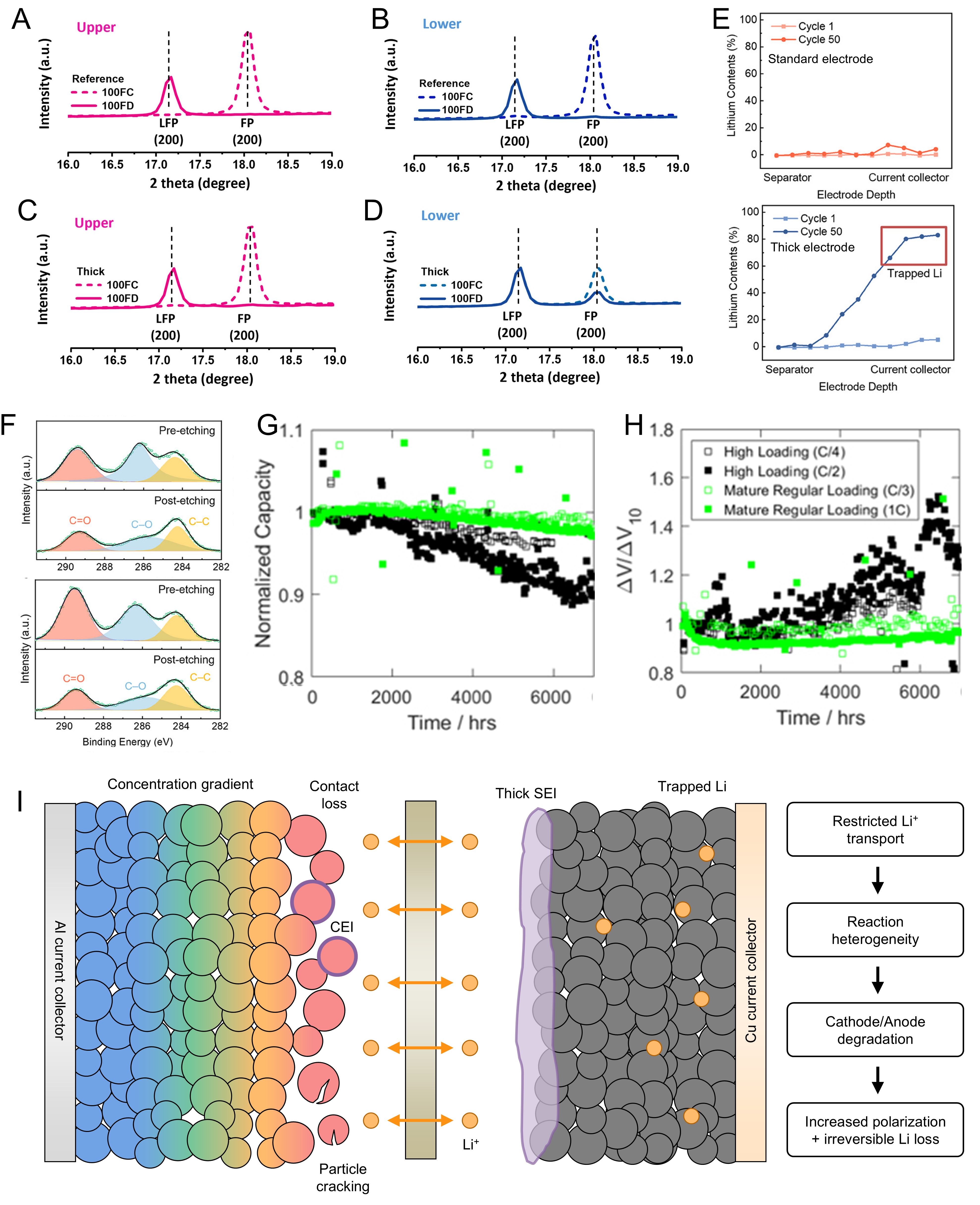
Figure 4. (A-D) Ex situ XRD patterns of the separator-facing and current-collector-facing regions of reference (A and B) and thick (C and D) LiFePO4 cathodes at the 100th charge and discharge states; (A-D) are reprinted with permission from Ref.[70] under a CC BY 4.0 license; (E) depth-resolved Li distribution obtained by laser-induced breakdown spectroscopy and (F) XPS results of cycled standard and thick graphite electrodes; (E and F) are reprinted with permission from Ref.[39], under CC BY NC-ND license; (G) normalized capacity retention and (H) normalized voltage polarization of regular- and high-loading NMC532/graphite pouch cells cycled at 20 °C under different C-rates; (G and H) are adapted from Ref.[91] under a CC BY 4.0 license; (I) schematic illustration of coupled degradation mechanisms in high-loading liquid-electrolyte LIBs. LFP: Lithium iron phosphate; FP: iron phosphate; CEI: cathode electrolyte interphase; SEI: solid electrolyte interphase; XRD: X-ray diffraction; NMC532: LiNi0.5Mn0.3Co0.2O2; XPS: X-ray photoelectron spectroscopy; LIB: Li-ion battery.