


Phosphate-tolerant PtCo alloys enabled by sulfur-doped carbon encapsulation for ultra-low-Pt-loading HT-PEMFCs
 0
0 Abstract
High-temperature proton exchange membrane fuel cells (HT-PEMFCs) have garnered considerable interest owing to their superior tolerance toward CO impurities and the inherent advantages of facile water management. However, severe phosphoric acid poisoning of Pt catalysts necessitates markedly higher Pt loadings than in low-temperature proton exchange membrane fuel cells, thereby constraining their large-scale deployment. Herein, we present an additive-assisted impregnation approach to synthesize ultrafine PtCo alloy nanoparticles encapsulated by defect-rich S-doped carbon encapsulation layers (CELs). The use of short-chain sodium thioglycolate enables the formation of ultrafine PtCo nanoparticles (~2.82 nm) coated with ~0.4 nm-thick CELs, effectively suppressing metal sintering during high-temperature annealing and strengthening metal-support interactions. The S-doped CELs provide dual protection against phosphoric acid poisoning by physically isolating the PtCo alloys and introducing negatively charged carbon defects to electrostatically repel phosphate anions. Consequently, the optimized sodium thioglycolate-PtCo alloy electrocatalyst delivers a high mass activity of 0.695 A mgPt-1 at 0.85 V along with enhanced durability in 0.1 M H3PO4 at 80 °C. It further maintains excellent phosphate tolerance and oxygen reduction reaction activity, even in concentrated 85 wt% H3PO4 at 120 °C. Remarkably, in HT-PEMFCs, it achieves superior peak power densities of 613 and 908 mW cm-2 in H2-air and H2-O2, respectively, with a low Pt loading of 0.3 mgPt cm-2. Even at an ultra-low Pt loading of 0.1 mgPt cm-2, it delivers a peak power density of
Keywords
INTRODUCTION
Proton exchange membrane fuel cells (PEMFCs) are renowned for directly converting chemical energy into electricity with high power output, superior energy conversion efficiency, and minimal environmental impact[1,2]. This technology holds significant promise as a key solution for achieving carbon neutrality and advancing sustainable development goals. High-temperature PEMFCs (HT-PEMFCs), based on phosphoric acid (PA)-doped polybenzimidazole (PBI) membranes, typically operate at temperatures ranging from
To reduce Pt loading in HT-PEMFCs and enhance the mass-specific peak power density of Pt, it is crucial to develop highly active, durable, and PA-resistant electrocatalysts. One promising approach is the formation of atomically ordered and structurally stable Pt-M alloys with 3d transition metals through high-temperature annealing. The enhanced oxygen reduction reaction (ORR) activity and stability arise from the robust 3d-5d orbital interactions between M and Pt[14,15]. However, a significant challenge of high-temperature annealing is metal sintering, which leads to a loss of electrochemical active surface area (ECSA) and consequently undermines the goal of reducing Pt loading[16,17]. Therefore, innovative strategies to prevent sintering while maintaining high ECSA are essential for obtaining high ORR performance.
Various strategies have been explored to improve the PA tolerance of catalysts. Firstly, modulating the d-band center of Pt can weaken the adsorption strength between phosphate and the Pt surface[10]. For example, Li et al. induced compressive strain in PtFe crystals through minor Cu doping, effectively weakening phosphate adsorption on Pt[18]. Secondly, forming a protective carbon coating layer can physically block PA from contacting the Pt surface[19]. Chougule et al. demonstrated this by preparing carbon molecular sieve layer (MSL) encapsulated Pt catalysts (Pt@MSL) through annealing Pt/C in H2/N2. The MSL allowed O2 access to Pt while blocking PA[20]. Thirdly, introducing substances with higher phosphate adsorption energies can preferentially adsorb PA, thereby protecting the Pt surface from poisoning[21]. Zhang et al. introduced defective g-C3N4 into Pt/C catalysts, where the abundant amine groups in g-C3N4 formed acid-base interactions with PA, thereby displacing PA from the Pt surface[22]. Additionally, optimizing PA distribution within the CL is essential to prevent "acid flooding"[12,23]. Binders such as polytetrafluoroethylene (PTFE) are often incorporated to reduce the affinity of the CL for PA, thereby preventing pore blockage by PA and ensuring proper reactant access[24,25]. These strategies highlight the multifaceted approach required to develop next-generation electrocatalysts for HT-PEMFCs that are PA-resistant and capable of maintaining high performance with reduced Pt loadings.
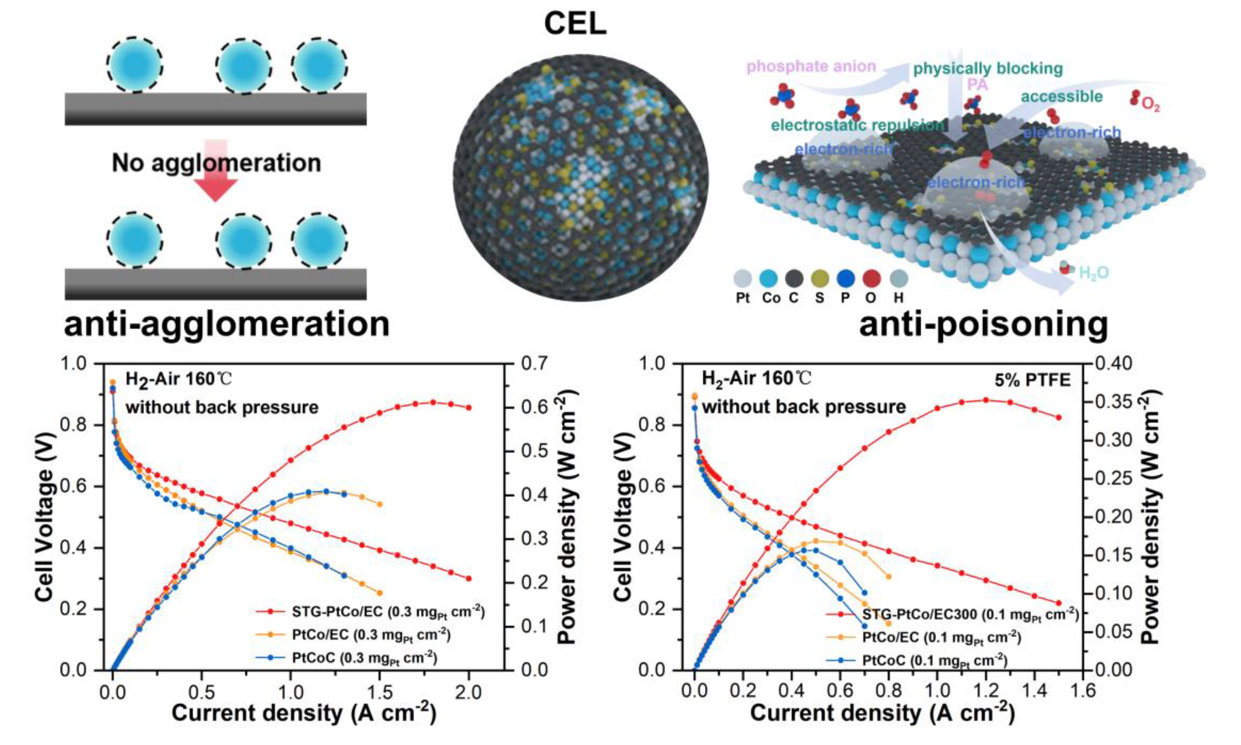
Inspired by prior research, we have pioneered a novel additive-assisted impregnation method for synthesizing small-sized PtCo alloy catalysts encapsulated by carbon encapsulation layers (CELs) of controllable thickness. As depicted in Figure 1, the coordination of sulfhydryl and carboxyl groups from the additives with Pt and Co ions leads to the formation of a bimetallic complex network. This network effectively inhibits metal sintering during high-temperature annealing. Moreover, upon carbonization, the additives generate defective S-doped CELs around the PtCo alloys. Our innovative approach leverages sodium thioglycolate (STG) to synthesize PtCo alloy electrocatalysts (STG-PtCo/EC) with superior ORR activity and stability in PA systems. The small PtCo particles (2.82 ± 0.5 nm) maximize the ECSA to
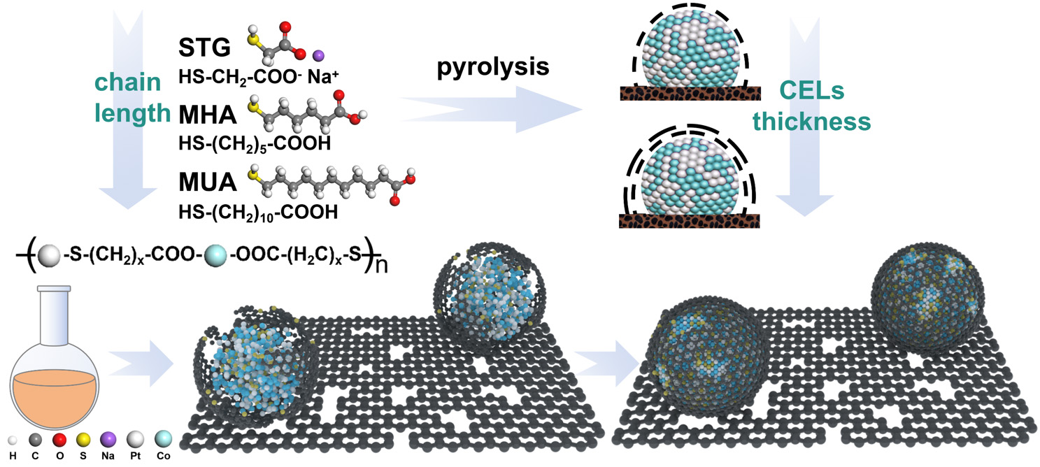
Figure 1. Schematic illustration of the synthesis of additive-assisted PtCo/EC samples.
EXPERIMENTAL
Materials and methods
Materials
All the information should be given in sufficient detail so that other scholars are able to reproduce the results. Chloroplatinic acid hexahydrate (H2PtCl6·6H2O, solid, 37.5% Pt basis), cobalt(II) chloride (CoCl2, solid, 99%), copper(II) chloride (CuCl2, solid, 99.99% metals basis), iron(III) chloride hexahydrate
Synthesis of small molecule-assisted PtCo/EC electrocatalysts
First, 0.57 mmol of a thiol-containing small molecule was first completely dissolved in 60 mL of solvent (DI water for STG and 6-Mercaptohexanoic acid (MHA), acetone for 11-Mercaptoundecanoic acid (MUA)). Next, 0.38 mmol of H2PtCl6 and 0.49 mmol of CoCl2 were dispersed into the prepared solution. Following this, 200 mg of carbon black (Ketjenblack EC-300J) was dispersed in 40 mL of isopropanol and then added to the metal ion-containing solution. After stirring for
Synthesis of STG-PtM/EC (M=Cu, Ni, Fe, Zn, Mn) electrocatalysts
The synthesis method is the same as that for STG-PtCo/EC, except that CoCl2 was replaced with the corresponding CuCl2, FeCl3·6H2O, NiCl2·6H2O, MnCl2·4H2O, and ZnCl2.
Materials characterization
The crystal structure of the synthesized samples was characterized using X-ray diffraction (XRD-6100) in a diffractometer equipped with Cu Kα radiation (λ = 0.1542 nm, 40 kV, 30 mA). The high-resolution transmission electron microscope (HR-TEM), high-angle annular darkfield scanning transmission electron microscopy (HAADF-STEM), and energy-dispersive X-ray (EDX) spectrometry mapping images were obtained using a Lorentz scanning transmission electron microscope (STEM, Talos F200X) equipped with Super X-EDS system at 200 kV. The Brunauer-Emmett-Teller (BET) surface area was determined via N2
The lattice strain and grain size were determined using the Williamson-Hall equation:
where βhkl denotes the full width at half maximum (FWHM) of the (hkl) diffraction peak, θ is the Bragg diffraction angle, k is the shape factor (k = 0.9), λ is the Cu Kα X-ray wavelength (1.5418 Å), D is the grain size (nm) and ε is the lattice strain.
RDE measurements
All electrochemical measurements were conducted using a CHI 760e workstation in a three-electrode configuration. A graphite rod served as the counter electrode, while an Ag/AgCl (3 M KCl) electrode was used as the reference. All reference potentials were calibrated against the reversible hydrogen electrode (RHE). To prepare the catalyst ink, 4 mg of the as-synthesized catalyst was dispersed with 990 μL of isopropanol, 990 μL of DI water, and 20 μL (5 wt %) Nafion solution. Subsequently, the ink was drop-coated onto a glassy carbon disk with a diameter of 5.0 mm, ensuring Pt loading of 15 µg cm-2. After drying at room temperature in air, the glassy carbon disk was used as the working electrode. All working electrodes were first activated by cycling the potential in N2-saturated 0.1 M HClO4 solution between 0 and 1.1 V at
where J represents the measured current density, while JK and JL denote the kinetic and diffusion-limited current densities, respectively.
The CO stripping tests were performed to calculate the ECSA. The electrolyte was initially saturated with CO for 10 min while maintaining the working electrode potential at 0.1 V vs. RHE, then bubbled N2 for
where SCO, V, and LPt denote the integration area of CO desorption, sweep rate, and Pt loading, respectively. The mass activity and specific activity were obtained by normalizing JK with respect to the Pt loading and ECSA on the working electrode, respectively.
The high-temperature rotating disk electrode (HT-RDE) device was similar to the traditional RDE three-electrode test, whereas the counter electrode was a Pt wire, and the reference electrode served as a RHE. The electrolyte was either 0.1 M HClO4 + 0.1 M H3PO4 at 80 °C or 85 wt% H3PO4 at 120 °C. The cell temperature was precisely controlled using a heating magnetic stirrer with an oil bath.
HT-PEMFCs tests
The cathode catalyst ink was prepared by dispersing the catalyst powder and PTFE into a mixed solvent of water and isopropanol with a 1:1 ratio. The ink was then sprayed onto a gas diffusion electrode (GDE) with a microporous layer (MPL) using pneumatic spray, covering an active electrode area of 4 cm2 (2 cm × 2 cm). For the low Pt loaded cathodic CLs, the Pt loading was controlled at 0.3 mg cm-2, and the thickness of CLs was maintained at 40-50 μm. In this case, the TANAKA-PtCoC catalyst with a Pt content of 46.9 wt% was selected as the control sample. For ultra-low Pt loaded cathodic CLs with Pt loading of 0.1 mg cm-2, the Pt content of the as-synthesized catalysts was reduced and the commercial PtCoC catalyst with a Pt content of 10 wt% was used as the control sample to maintain the thickness of CLs at an appropriate 40-50 μm to prevent "acid flooding". JM Pt/C was employed as the anode catalyst, with a Pt loading of 0.1 mg cm-2, a catalyst layer thickness of ~20 μm, and a PTFE content of 10 wt%.
The PBI membrane was immersed in 85 wt% H3PO4 to obtain the PA-doped PBI membrane with PA content of 400 wt%. The membrane was then sandwiched between the cathode and anode GDEs and hot-pressed at 160 °C under 1 MPa for 5 min to fabricate the membrane electrode assembly (MEA).
The performance of HT-PEMFC was tested at 160 °C; dry H2/air (H2/O2) was used as the anode/cathode inlet gases with the flow rate of 100/400 (100/200) sccm and without back pressure. The MEA was first activated at a current density of 0.5 A cm-2. Subsequently, polarization curves were recorded by adjusting the cell current and monitoring the resulting voltage. Electrochemical impedance spectroscopy (EIS) measurements were conducted by sweeping frequencies from 20 kHz to 0.1 Hz under a DC voltage of 0.6 V. Cyclic voltammetry (CV) was performed at 160 °C with dry H2/N2 as the anode/cathode supplied gases and the scan was conducted from 0 to 1.2 V at a sweep rate of 50 mV s-1.
RESULTS AND DISCUSSION
Morphology and structure characterization
TEM images [Figure 2A and B] of the STGPtCo/EC electrocatalyst reveal that the ultrafine PtCo nanoparticles are uniformly distributed on the carbon support and surrounded by amorphous CELs. A high-resolution transmission electron microscopy (HR-TEM) image shows lattice spacings of 0.223 nm and 0.188 nm, corresponding to the (111) and (002) planes of PtCo, respectively [Figure 2C]. Energy-dispersive spectroscopy (EDS) mapping shows the co-localization of Pt, Co, and S elements within the particles of STG-PtCo/EC, indicating that S derived from the STG is incorporated into the CELs during thermal treatment [Figure 2D]. Moreover, EDS spectra [Supplementary Figure 1] further confirm the presence of S element, corroborating successful S-doping in the CELs. Notably, varying the carbon chain length of the additives enables precise control over the size of the PtCo nanoparticles and the thickness of the CELs. Using STG (C2), MHA (C6), and MUA (C11) as additives yields PtCo nanoparticles with average sizes of
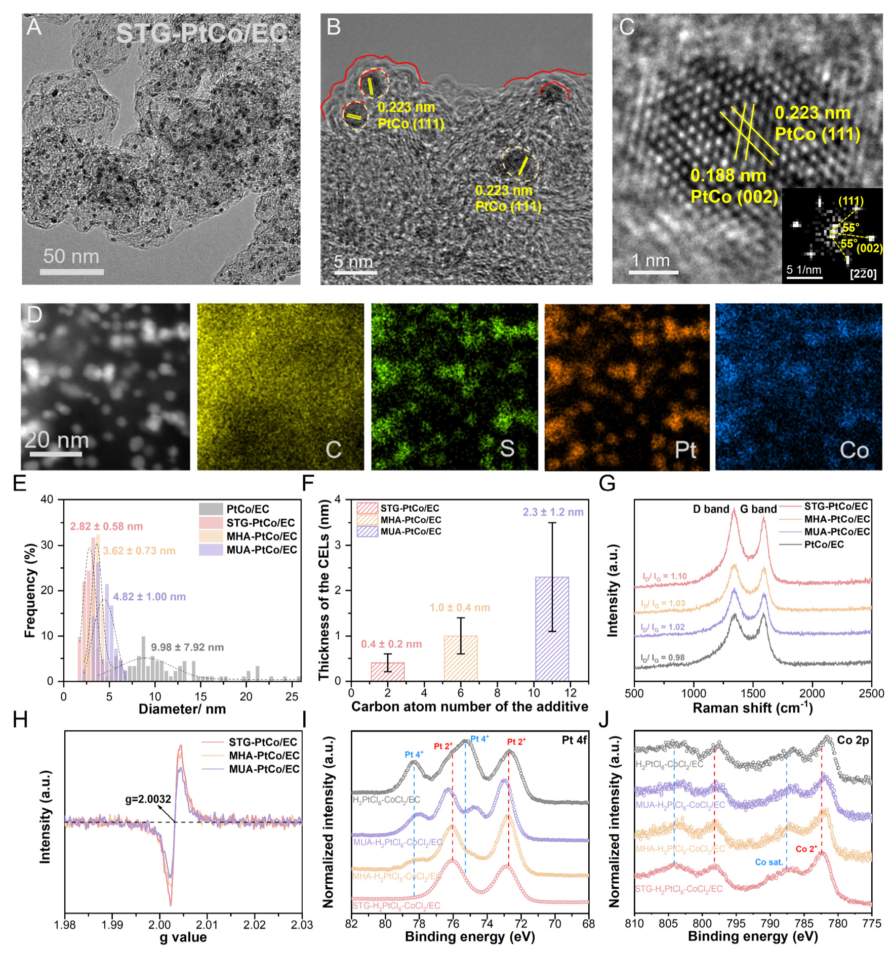
Figure 2. (A and B) TEM images and (C) HR-TEM image of STG-PtCo/EC. (D) HAADF-STEM image and EDS mapping images of STG-PtCo/EC. (E) Particle size distribution of the prepared electrocatalysts. (F) Thickness of the carbon encapsulation layer on the prepared electrocatalysts. (G) Raman spectra and (H) EPR spectra of the as-synthesized electrocatalysts. XPS spectra of (I) Pt 4f and (J) Co 2p for the additive-assisted and additivefree H2PtCl6-CoCl2/EC precursor powders.
Raman spectroscopy combined with N2 adsorption-desorption analysis was employed to elucidate the effects of S-doping on the defect structure and specific surface area of the carbon support. The two peaks at approximately 1,330 and 1,590 cm-1 in the Raman spectra [Figure 2G] correspond to the D band (associated with structural defects) and the G band (related to the crystallinity of sp2-hybridized carbon), respectively. STG-PtCo/EC exhibits the highest peak intensity ratio (ID/IG), indicating that S-doping introduced by STG leads to the highest defect density[27]. Nitrogen ad-/de-sorption isotherms indicate that all samples exhibit type IV isotherms with H4 hysteresis loops, suggesting the presence of both micropores and mesopores[28,29]. Compared with the additivefree PtCo/EC, the BET surface areas of the additive-assisted samples decrease markedly (PtCo/EC: 977.7 m2 g-1 > STG-PtCo/EC: 728.3 m2 g-1 > MHA-PtCo/EC: 395.8 m2 g-1 > MUA-PtCo/EC: 318.0 m2 g-1), primarily because the CELs cover the intrinsic micropores and mesopores of the carbon support. Notably, STG-PtCo/EC exhibits a higher porevolume distribution at ~0.68 nm, which is attributed to the formation of carbon defects within the CELs induced by S-doping
To investigate the role of additives in enhancing particle sintering resistance and forming S-doped CELs, UV-Vis spectroscopy and XPS analyses were conducted. Upon the addition of additives to the H2PtCl6 aqueous solution, the solution exhibits a discoloration from light yellow to orange, indicating an altered coordination environment of Pt [Supplementary Figure 8]. The UV-Vis spectral variations confirm that sulfhydryl and carboxyl groups in the additives coordinate with Pt(IV) and Co(II), respectively, forming a bimetallic complex network (detailed analysis is shown in Supplementary Figure 9).
Pt 4f XPS spectra of H2PtCl6-CoCl2/EC reveal four characteristic peaks at 72.7/76.1 eV and 75.3/78.3 eV, corresponding to Pt(II) and Pt(IV) species, respectively. As the additive chain length decreases, the Pt(IV) signals progressively attenuate while the Pt(II) component increases, suggesting partial substitution of Cl ligands by sulfhydryl groups, thereby enhancing the electron density around Pt [Figure 2I]. Co 2p XPS spectra exhibit a positive binding-energy shift as the additive chain length decreases, which is attributed to the electron-withdrawing carboxyl groups coordinating with Co(II) [Figure 2J]. This bimetallic complex network can reduce the nucleation and growth energy barrier of the PtCo alloy. During high-temperature annealing (900 °C, 3 h), the network decomposes, enabling Pt and Co atoms to nucleate into PtCo clusters with a 1:1 stoichiometry [Supplementary Table 1], while the additive carbon chains carbonize to form CELs around the PtCo clusters. Meanwhile, a minor fraction of S atoms from the sulfhydryl groups is incorporated into the CELs, generating carbon defects [Supplementary Table 2]. Subsequent low-temperature annealing (600 °C, 6 h) promotes the rearrangement of Pt and Co atoms to form ordered PtCo alloys. The physical confinement by CELs and the chemical interaction between Pt and S prevent the sintering of PtCo into larger particles during annealing[1,30].
X-ray diffraction (XRD) patterns exhibit an ordered crystal structure matching the PtCo alloy, adopting a tetragonal structure in the P4/mmm space group [Figure 3A]. Notably, as the additive chain length decreases, the XRD characteristic peaks progressively broaden, accompanied by a negative shift of the (111) diffraction peak, indicating that shorter-chain additives lead to the formation of smaller PtCo particles along with lattice tensile strain[31-33]. The average particle sizes, calculated using the Williamson-Hall equation based on the FWHM of the XRD peaks[34-36], follow the order: PtCo/EC (9.24 nm) > MUA-PtCo/EC
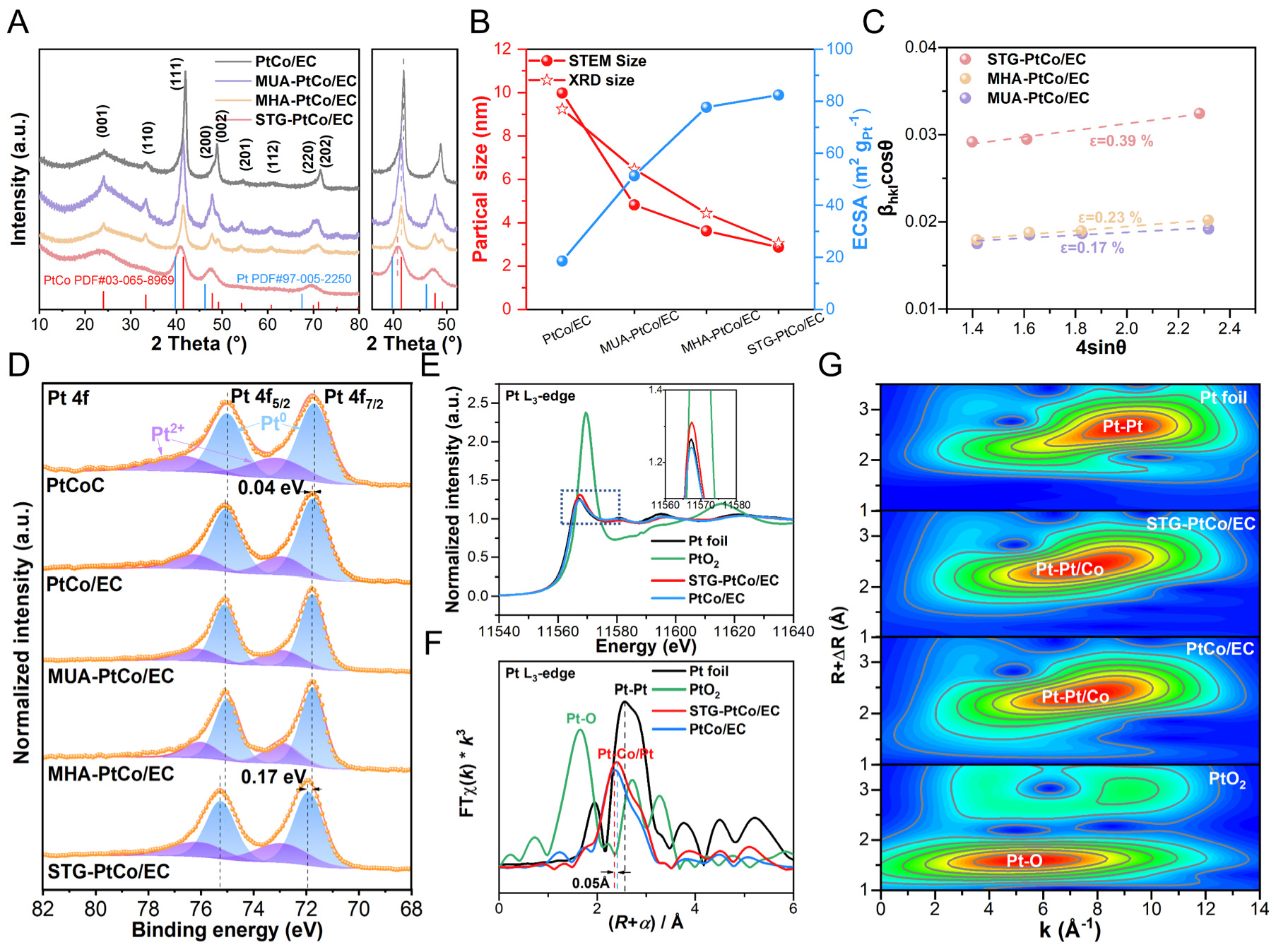
Figure 3. (A) XRD patterns. (B) Relationship between particle size and ECSA. (C) Estimated lattice strain (ε) from the Williamson-Hall plots. (D) XPS spectra of Pt 4f of the as-prepared samples. (E) Normalized XANES spectra, (F) Fourier-transformed EXAFS spectra and (G) Wavelet transform spectrum of Pt L3-edge.
XPS is employed to investigate the electronic structure and surface chemical states of the catalysts. The XPS survey spectra of STG-PtCo/EC reveal the presence of C, Pt, Co, S, and O signals, which is consistent with the expected composition [Supplementary Figure 10]. The C 1s XPS spectra reveal a peak associated with the C-S bonds at 285.7 eV for additive-assisted PtCo/EC, whose intensity progressively increases with decreasing additive chain length, indicating that S from the additives is thermally converted and doped into the CELs [Supplementary Figure 11A][39,40]. The Co 2p XPS spectra show an increase in metallic Co (Co0) content with shorter additive chain lengths, indicating that shorter chain additives facilitate the reduction of Co2+ to Co0 during thermal treatment [Supplementary Figure 11B, Supplementary Table 3]. The Pt 4f spectra [Figure 3D] reveal peaks corresponding to metallic Pt (Pt0) and oxidized Pt (Pt2+) species[35,41]. Compared to commercial PtCoC, the binding energies of Pt in PtCo/EC, MHA-PtCo/EC, and MUA-PtCo/EC exhibit only a slight positive shift of ~0.04 eV, whereas the STG-PtCo/EC sample shows a pronounced positive shift of 0.17 eV. This substantial shift indicates that S-induced carbon defects in the CELs enhance the MSI, thereby promoting electron transfer from Pt to adjacent S atoms within the CELs and subsequently redistributing to the surrounding C matrix and neighboring Co atoms.
The X-ray absorption near edge structure (XANES) and EXAFS analyses were performed on STG-PtCo/EC and related samples to elucidate the valence states and coordination environments of Pt. The white-line intensity of the Pt L3-edge XANES for STG-PtCo/EC lies between that of Pt foil and PtO2, yet closer to Pt foil, indicating that the valence state of Pt in STG-PtCo/EC falls between 0 and +4, and more closely aligned with the metallic state. The higher intensity of STG-PtCo/EC compared to PtCo/EC suggests that the introduction of STG promotes electron transfer from Pt to Co and defect-rich S-doped CELs, resulting in more unoccupied Pt 5d orbitals [Figure 3E][26,42]. The k3-weighted EXAFS spectra at the Pt L3-edge show a prominent peak for Pt foil at 2.55 Å [Figure 3F], corresponding to the first-shell Pt-Pt coordination. The peaks for the PtCo alloys shift to shorter radial distances (~2.39 Å) for both STG-PtCo/EC and PtCo/EC, indicating Pt-Co/Pt bonding resulting from alloy-induced atomic rearrangements. Notably, the peak position for STG-PtCo/EC exhibits an additional increase in radial distance of approximately 0.05 Å compared with PtCo/EC, suggesting lattice expansion caused by stronger MSI[43]. This variation is further corroborated by the wavelet transform analysis [Figure 3G]
Collectively, these results indicate that the strong MSI between the S-doped CELs and PtCo alloys induces tensile lattice strain, which upshifts the Pt d-band center and alters the electronic structure, thereby optimizing the adsorption strength of oxygenated intermediates and enhancing ORR activity[44,45].
ORR performance at room temperature
The ORR performance of the synthesized catalysts was initially evaluated in 0.1 M HClO4 at 25 °C using a RDE. Polarization curves reveal that the half-wave potential (E1/2) for commercial PtCoC, PtCo/EC, STG-PtCo/EC, MHA-PtCo/EC and MUA-PtCo/EC catalysts are 0.910, 0.807, 0.908, 0.904 and 0.900 V (vs. RHE), respectively [Figure 4A, Supplementary Figure 12]. Meanwhile, STG-PtCo/EC exhibits the lowest Tafel slope (67.6 mV dec-1), the highest mass activity (1.389 A mgPt-1) and specific activity
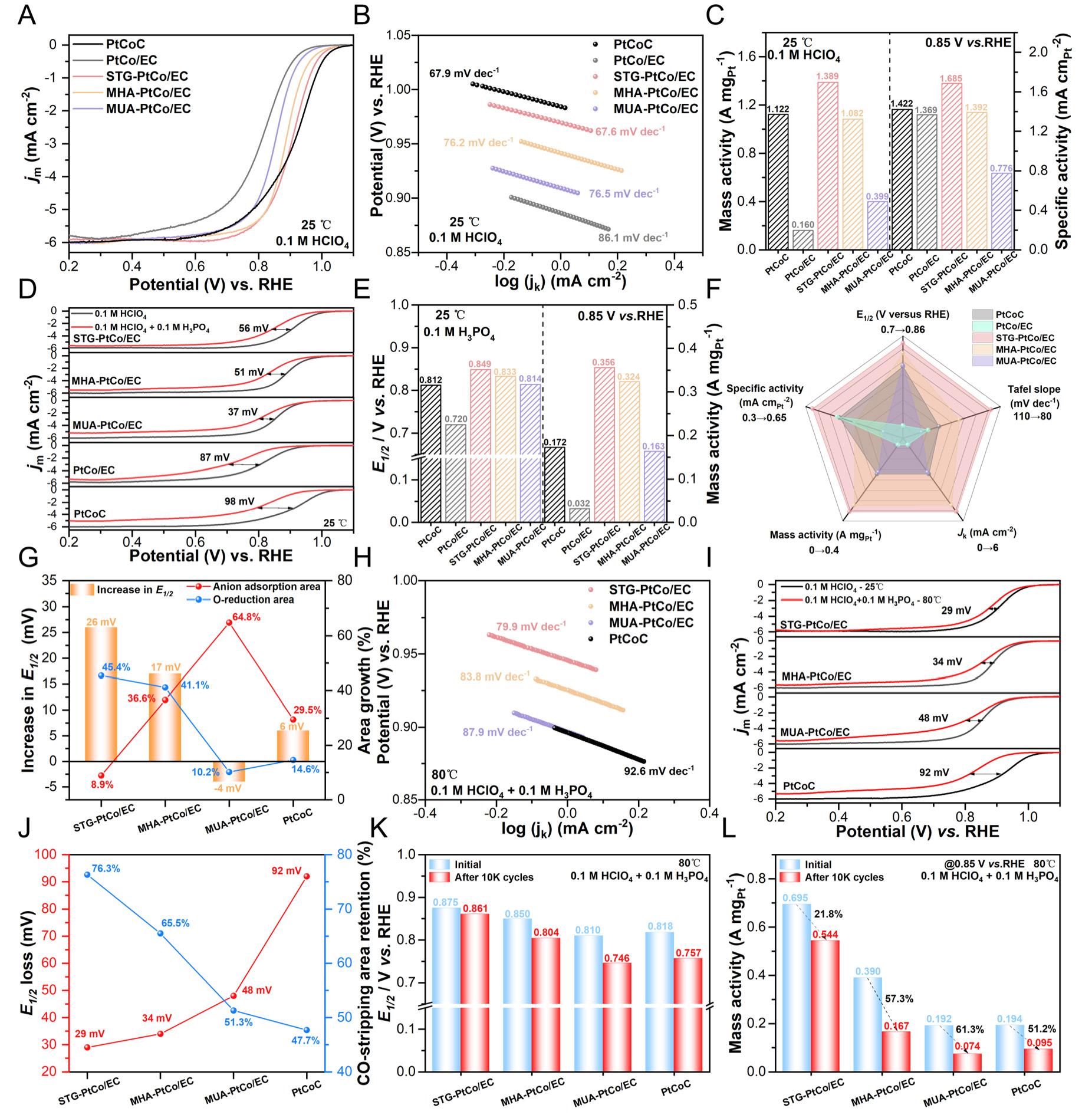
Figure 4. (A) ORR polarization curves and (B) Tafel plots of the synthesized catalysts and commercial PtCoC in O2-saturated 0.1 M HClO4 at 25 °C. (C) The MA and SA of the synthesized catalysts at 0.85 V vs. RHE in O2-saturated 0.1 M HClO4 at 25 °C. (D) ORR polarization curves comparison, (E) E1/2 and MA comparison in 0.1 M HClO4 and 0.1 M HClO4 + 0.1 M H3PO4 at 25 °C. (F) Radar chart of ORR performance for the synthesized catalysts in 0.1 M HClO4 + 0.1 M H3PO4 at 25 °C. (G) Correlation among phosphate anion coverage, O-reduction area, and the increment in E1/2 for the synthesized catalysts as the testing temperature increases from 25 °C to 80 °C in 0.1 M HClO4 + 0.1 M H3PO4. (H) Tafel Slopes in 0.1 M HClO4 + 0.1 M H3PO4 at 80 °C. (I) ORR polarization curves comparison in 0.1 M HClO4 at 25 °C and 0.1 M HClO4 + 0.1 M H3PO4 at 80 °C. (J) Correlation of the E1/2 decay values and CO-stripping area retention in 0.1 M HClO4 at 25 °C and in 0.1 M HClO4 + 0.1 M H3PO4 at 80 °C, Retention% = (value in 0.1 M HClO4 + 0.1 M H3PO4/value in 0.1 M HClO4) × 100%. (K) Comparison of E1/2 and (L) MA of the synthesized catalysts after 10,000 potential cycles in 0.1 M HClO4 + 0.1 M H3PO4 at 80 °C.
To evaluate the resistance of the catalysts to PA poisoning, the ORR performance was compared in O2-saturated 0.1 M HClO4 and 0.1 M HClO4 + 0.1 M H3PO4 solutions at room temperature. The linear sweep voltammetry (LSV) curves reveal that, compared with the HClO4 system, all catalysts exhibit a negative shift in E1/2 in the PA-containing electrolyte, accompanied by a decrease in diffusion-limited current density (JL). The negative shifts of E1/2 follow the order: MUA-PtCo/EC (37 mV) < MHA-PtCo/EC (51 mV) < STG-PtCo/EC (56 mV) < PtCo/EC (87 mV) < commercial PtCoC (98 mV), indicating that the additive-assisted PtCo/EC catalysts possess resistance to PA poisoning [Figure 4D].
CV curves confirm the poisoning effect of phosphate anions on Pt sites [Supplementary Figure 13]. The CV curves in the PA-containing electrolyte exhibit a new peak at approximately 0.28 V, corresponding to the adsorption of phosphate anions on the Pt surface, resulting in surface reconstruction and introducing additional positive charges on Pt due to the shift in the potential of zero charge (pzc)[46,47]. The peak appearing at 0.4-0.7 V corresponds to the adsorption/desorption of phosphate anions[48]. Phosphate adsorption markedly decreases the peak area related to oxide formation/reduction region (Pt-O(H),
The decrease in ECSA was evaluated through CO-stripping measurements [Supplementary Figure 14]. By establishing the correlation among the E1/2 decay, ECSA retention, and MA retention, it is evident that MUA-PtCo/EC exhibits the best resistance to PA poisoning at room temperature, which can be attributed to its relatively thicker CELs that physically hinder the contact between PA molecules and the PtCo surface
All catalysts exhibit increased Tafel slopes in the PA-containing electrolyte, indicating that phosphate anions inhibit the ORR kinetics [Supplementary Figure 16][49]. Although MUA-PtCo/EC exhibits the highest ECSA retention, the excessively thick CELs impede mass diffusion, hindering O2 access to the active sites, resulting in low specific activity (0.369 mA cmPt-2) and slower reaction kinetics (Tafel
The i-t curves at a constant potential of 0.7 V reflect the stability of the catalysts in the PA-containing system [Supplementary Figure 19]. The ORR polarization curves before and after the i-t test indicate that STG-PtCo/EC exhibits the smallest ΔE1/2 of 79 mV [Supplementary Figure 20]. The excellent stability of STG-PtCo/EC in the PA-containing system can be ascribed to the incorporation of S into the CELs, which introduces negatively charged carbon defects. These defects electrostatically repel phosphate anions, thereby suppressing their adsorption on Pt active sites or facilitating their rapid desorption.
ORR performance in PA electrolytes at high temperature
Compared to room-temperature evaluations, assessing the phosphate tolerance of catalysts at high temperatures is more critical, as it better reflects their practical applicability in HT-PEMFCs. It is well established that the dissociation of PA is an endothermic process; therefore, elevated temperatures promote its dissociation, leading to an increased concentration of phosphate anions, which may further enhance the coverage of Pt active sites. The relationship between ORR current density, temperature, and the accessible active sites is given by
where j is the current density; n, F, K, and R represent the number of electrons, Faraday constant, reaction rate constant, and gas constant, respectively. χ denotes the exponential factor; β and γ are symmetry factors; cO2 is the O2 concentration in the solution; θad is the total surface coverage (including OHad and adsorbed phosphate species), E is the applied potential, T is the temperature, and ΔGad is the Gibbs free energy of adsorption for the oxygen-containing intermediate[50].
This equation indicates that the elevated temperatures favor the enhancement of ORR kinetics in the absence of specifically adsorbed anions. However, in PA-containing media, increasing temperature substantially raises the concentration of phosphate anions, thereby intensifying the total surface coverage
The ORR performance of the synthesized catalysts in 0.1 M HClO4 + 0.1 M H3PO4 solution was evaluated at 80 °C using a high-temperature RDE setup [Supplementary Figure 21]. The LSV curves demonstrate that STG-PtCo/EC exhibits the highest ORR activity [Supplementary Figure 22]. Compared with the LSV curves at 25 °C, elevating the operating temperature to 80 °C results in positive shifts in E1/2 of 26, 17, and 6 mV for STG-PtCo/EC, MHA-PtCo/EC, and commercial PtCoC, respectively, indicating enhanced ORR activity. In contrast, MUA-PtCo/EC exhibits a negative shift of 4 mV, suggesting a decline in its ORR activity at elevated temperature [Figure 4G].
The CV curves elucidate the underlying causes of these changes [Supplementary Figure 23]. Upon increasing the temperature to 80 °C, the peak area corresponding to phosphate anion adsorption in the range of
The Tafel plots reveal that elevating the temperature to 80 °C reduces the Tafel slopes of all as-synthesized catalysts, indicating enhanced ORR kinetics at higher temperatures. Notably, STG-PtCo/EC exhibits the smallest Tafel slope (79.9 mV dec-1), confirming its superior ORR activity in the high-temperature, PA-containing electrolyte [Figure 4H].
Further comparison with the ORR polarization curves obtained at 25 °C in 0.1 M HClO4 reveals that the negative shifts in E1/2 follow the order: STG-PtCo/EC (29 mV) < MHA-PtCo/EC (34 mV) < MUA-PtCo/EC (48 mV) < commercial PtCoC (92 mV), demonstrating the superior resistance of STG-PtCo/EC to PA poisoning at higher temperatures [Figure 4I and Supplementary Figure 24]. CO-stripping voltammograms were used to evaluate the ECSA retention, providing insight into the poisoning effects of the catalysts in high-temperature conditions [Supplementary Figure 25]. All catalysts exhibit a negative shift in the CO oxidation peak at 80 °C, which is attributed to the accelerated oxidation of COad to CO2 at elevated temperatures, allowing the reaction to initiate at lower potentials. The CO-stripping area retention serves as an indicator for the preservation of accessible electrochemically active surface sites. For STG-PtCo/EC, MHA-PtCo/EC, MUA-PtCo/EC, and commercial PtCoC, the CO-stripping area retentions are 76.3%, 65.5%, 51.3%, and 47.7%, respectively, exhibiting an inverse correlation with the shifts in E1/2. This suggests that the loss of accessible active sites plays a dominant role in the observed ORR performance degradation
STG-PtCo/EC exhibits a maximum mass activity of 0.695 A mgPt-1 @ 0.85 V at 80 °C, which is 3.58 times of commercial PtCoC (0.194 A mgPt-1). After 10,000 accelerated durability test (ADT) cycles at 80 °C in 0.1 M HClO4 + 0.1 M H3PO4, it exhibits only 14 mV negative shift in E1/2 and 21.8% mass activity loss, demonstrating robust high-temperature durability [Figure 4K and L, Supplementary Figure 26].
After the ADT test, TEM characterization was performed on the catalysts. The results reveal that commercial PtCoC undergoes severe particle agglomeration, leading to a significant increase in the average particle size [Supplementary Figure 27A-C]. In contrast, no pronounced agglomeration is observed for the additive-assisted catalysts, whose particle size distribution and lattice fringe spacing remain nearly unchanged before and after testing [Supplementary Figure 27D-L]. These findings indicate that the CELs effectively suppress PtCo particle dissolution, migration, and aggregation during electrochemical operation through physical confinement, thereby enhancing both thermodynamic and dynamic stability. Since no particle agglomeration is observed, the performance degradation of these catalysts is mainly attributed to the cumulative coverage of phosphate anions on the catalyst surface.
To further investigate the practical applicability of the catalysts, HT-RDE tests were conducted in 85 wt%
The ORR polarization curves reveal that STG-PtCo/EC maintains the highest performance in 85 wt% H3PO4 at 120 °C, with the E1/2 of 0.942 V, surpassing those of MHA-PtCo/EC (0.932 V), MUA-PtCo/EC (0.909 V), and commercial PtCoC (0.853 V). Notably, a kink is observed in the LSV curves between 0.7-0.8 V, attributed to the slow O2 diffusion in the high-concentration PA solution, which cannot meet the oxygen consumption at the electrode surface[52]. Furthermore, STG-PtCo/EC exhibits the highest diffusion limited current density (jL) of 0.450 mA cm-2, exceeding those of MHA-PtCo/EC (0.293 mA cm-2), MUA-PtCo/EC (0.288 mA cm-2), and commercial PtCoC (0.309 mA cm-2) [Figure 5A and B]. This superior performance is attributed to the S-doped CELs with optimal thickness, which not only physically block direct contact between PA and Pt sites but also electrostatically repel phosphate anions via negatively charged carbon defects, thereby effectively reducing surface phosphate coverage without hindering O2 access to active sites.
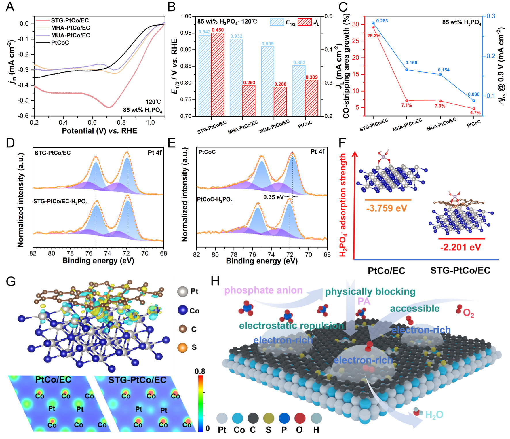
Figure 5. (A) ORR polarization curves of the synthesized catalysts and commercial PtCoC in O2-saturated 85 wt% H3PO4 at 120 °C. (B) Comparison of E1/2 and JL of the catalysts in 85 wt% H3PO4 at 120 °C. (C) Relationship between the CO-stripping area growth and Δjm @ 0.9 V as the testing temperature increases from 25 °C to 120 °C in 85 wt% H3PO4. Pt 4f XPS spectra of (D) STG-PtCo/EC and (E) commercial PtCoC before and after being treated with 85 wt% H3PO4 at 160 °C for 18 h. (F) Geometric structure and adsorption strength of H2PO4- on the PtCo (111) surface of PtCo/EC and STG-PtCo/EC. (G) The differential charge density map of the STG-PtCo/EC samples (the yellow and green represent regions of electron accumulation and depletion, respectively) and the charge density maps of PtCo/EC and STG-PtCo/EC. (H) Schematic diagram of S-doped CELs assisting PtCo in resisting H2PO4- adsorption.
The growth in CO-stripping peak area and Δjm @ 0.9 V at 120 °C highlights the superior phosphate tolerance of STG-PtCo/EC. Its CO-stripping peak area increases by 29.2%, substantially higher than that of other samples, indicating that the presence of negatively charged carbon defects preserved more unoccupied active sites despite the elevated phosphate anion concentration at higher temperatures [Figure 5C and Supplementary Figure 29].
To simulate the adsorption behavior of phosphate anions on catalysts under HT-PEMFC operating conditions, the synthesized catalysts were treated with 85 wt% H3PO4 solution at 160 °C for 18 h under an Ar atmosphere. XRD patterns before and after PA treatment exhibit no discernible changes
To investigate the anti-PA performance of the catalysts, we chose H2PO4- as the representative spectator species, because it is the predominant phosphate anion under operating conditions and the principal contributor to Pt catalyst poisoning. The adsorption behavior of H2PO4- was simulated on the PtCo (111) facet, which represents the catalytically active surface. H2PO4- adsorbs onto the Pt surface through two O atoms, which is consistent with previous reports [Supplementary Figure 33][53]. The adsorption energies of H2PO4- on both STG-PtCo/EC and PtCo/EC surfaces are negative, indicating that the adsorption process is spontaneous. Notably, the adsorption energy on STG-PtCo/EC (111) is -2.201 eV (smaller in magnitude), suggesting a weaker interaction and thus superior phosphate tolerance. In contrast, PtCo/EC (111) exhibits a stronger interaction, with an adsorption energy of -3.759 eV (larger in magnitude), which accounts for its more severe susceptibility to phosphate poisoning. The results indicate that the S-doped CELs substantially weaken H2PO4- adsorption on the PtCo surface, thereby mitigating active-site poisoning [Figure 5F]. The differential charge density plot [Figure 5G] reflects an enhanced MSI between the S-doped CELs and PtCo alloys. Electrons from Pt atoms partially transfer to adjacent S atoms within the CELs and are subsequently redistributed to the surrounding C matrix and neighboring Co atoms. This electronic redistribution weakens the adsorption strength of phosphate species and promotes ORR kinetics. Figure 5H illustrates the anti-PA mechanism of the STG-PtCo/EC electrocatalyst, wherein the CELs physically isolate the PtCo alloys from PA, while the negatively charged carbon defects electrostatically repel phosphate anions, thereby suppressing their adsorption or facilitating their desorption on Pt sites.
HT-PEMFC performance with low Pt loading
To investigate the performance of the catalysts in HT-PEMFCs, MEAs (2 × 2 cm2) were fabricated using the synthesized electrocatalysts as cathodes, commercial Pt/C as anodes, and PA-doped PBI membranes as proton exchange membranes. To eliminate the effects on the anode side, the Pt loading at the anode was set in excess (0.3 mgPt cm-2), while the cathode loading was controlled at 0.3 mgPt cm-2. As shown in the H2-air fuel cell polarization curves [Figure 6A], STG-PtCo/EC achieves a peak power density of 613 mW cm-2, outperforming PtCo/EC (405 mW cm-2) and commercial PtCoC (411 mW cm-2). Under H2-O2 conditions, STG-PtCo/EC delivers a peak power density of 908 mW cm-2, markedly higher than that of PtCo/EC
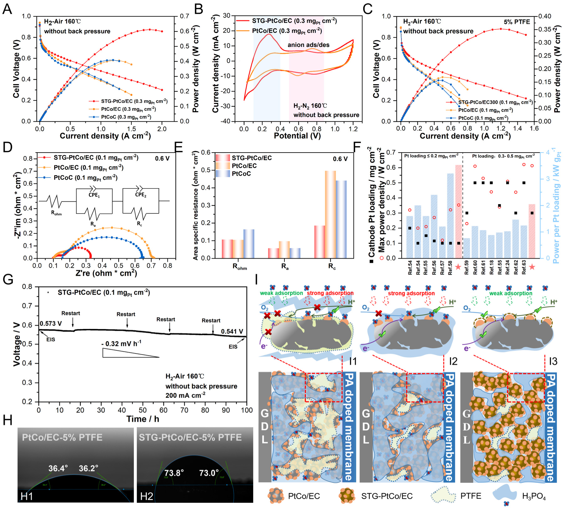
Figure 6. (A) Polarization and power density curves with low Pt loading (0.30 mgPt cm-2 in the cathode) at 160 °C (H2/air) without back-pressure. (B) CV of the MEAs at 160 °C (H2/N2). (C) Polarization and power density curves and (D) EIS analysis at 0.6 V (inset: equivalent circuit) with ultra-low Pt loading (0.10 mgPt cm-2 in the cathode) at 160 °C (H2/air) without back-pressure. (E) Fitted values of various impedances from (D). (F) Performance comparison of the H2-air HT-PEMFCs with the low-Pt-loadings below
When the cathode Pt loading is further reduced to 0.1 mgPt cm-2, the PTFE content in the CL significantly influences MEA performance[3]. For STG-PtCo/EC, the optimal performance is achieved at 5 wt% PTFE in the cathode CL [Supplementary Figure 35]. Conversely, the absence of PTFE leads to performance decay due to the excessive affinity of the CL for PA, causing "acid flooding" and a reduction of three-phase interfaces[25,64]. The H2-air fuel cell polarization curves in Figure 6C demonstrate that STG-PtCo/EC delivers a peak power density of 355 mW cm-2, significantly exceeding PtCo/EC (170 mW cm-2) and commercial PtCoC (156 mW cm-2). At 0.6 V, STG-PtCo/EC exhibits lower anode impedance (Ra, high-frequency region) and cathode impedance (Rc, low-frequency region) than PtCo/EC and PtCoC [Figure 6D and E, Supplementary Figure 36], indicating that the S-doped CELs not only protect the active sites from PA poisoning but also optimize PA distribution within the MEA, preventing PA loss at the anode CL due to excessive PA affinity at the cathode CL[24,65]. STG-PtCo/EC and PtCo/EC show lower ohmic resistance than commercial PtCoC, attributed to the superior conductivity of the Ketjenblack EC-300J carbon support. The ultra-low-Pt-loading MEA with STG-PtCo/EC exhibits a remarkably high Pt utilization, achieving a cathode Pt power density of 3.53 kW gPt-1, which reaches the advanced level of current low-Pt HT-PEMFCs
Durability testing demonstrates that the ultra-low-Pt-loading MEA with STG-PtCo/EC exhibits a voltage decay rate of 0.32 mV h-1 over 100 h at a constant current of 200 mA cm-2 [Figure 6G]. Post-test analysis shows an increase in ohmic resistance, likely due to PA migration from the PBI membrane to the CL[66]. Meanwhile, the cathode impedance slightly decreased, indicating improved interfacial kinetics due to a more uniform PA distribution within the cathode CL of STG-PtCo/EC, which mitigates acid flooding and active-site poisoning while constructing rapid proton transport pathway. Conversely, a marked increase in anode impedance is observed, possibly attributed to PA poisoning of the commercial Pt/C anode catalyst, slowing the hydrogen oxidation reaction (HOR) [Supplementary Figure 41][24].
Contact angle measurements of PA on the electrode surface reveal that both STG-PtCo/EC and PtCo/EC with 20wt% PTFE in the CL exhibit repellent behavior toward PA [Supplementary Figure 42A and B]. PtCo/EC with 0 or 5 wt% PTFE exhibits excessive affinity for PA [Figure 6H1 and
EDS spectra of CL cross-section corroborate these findings: for PtCo/EC with 5 wt% PTFE, relatively strong P and O signals indicate significant PA adsorption on the CL surface [Supplementary Figure 43A], whereas the signals are markedly weaker for STG-PtCo/EC, confirming reduced PA adsorption
CONCLUSIONS
In summary, we have developed an additive-assisted impregnation strategy to synthesize S-doped carbon-encapsulated PtCo alloy catalysts with precisely controlled particle size and encapsulation layer thickness. The defect-rich S-doped CELs effectively inhibit metal sintering, enhance MSIs, and provide dual protection against PA poisoning through physical isolation and electrostatic repulsion. Consequently, the optimized STG-PtCo/EC catalyst exhibits excellent ORR activity, remarkable phosphate tolerance, and outstanding stability under harsh PA-containing conditions. When applied in HT-PEMFCs, it achieves superior peak power densities of 613 and 908 mW cm-2 in H2-air and H2-O2, respectively, with a low Pt loading of
DECLARATIONS
Authors’ contributions
Conceptualization, methodology, investigation, data curation, formal analysis, writing-original draft:
Methodology, investigation, formal analysis: Chen, Z.; Qiu, P.; Cao, J.; Bai, J.; Ji, F.
Conceptualization, methodology, investigation, formal analysis, funding acquisition, supervision, writing review and editing: Chen, Z.; Deng, C.; Shu, C.; Tang, W.
Availability of data and materials
All detailed materials and methods supporting the results of this study are included in the article/Supplementary Materials. Further inquiries can be directed to the corresponding author(s).
AI and AI-assisted tools statement
Not applicable.
Financial support and sponsorship
This work was supported by the following funding sources: the National Key R&D Program of China (2021YFB2400400), the National Natural Science Foundation of China (Grant Nos. 22409157, 22379120), the Key Research and Development Plan of Shanxi Province (China, Grant Nos. 2018ZDXM-GY-135, 2021JLM-36), the China Postdoctoral Science Foundation (2020M673408), the Higher Education Institution Academic Discipline Innovation and Talent Introduction Plan (“111 Plan”) (No. B23025), the Fundamental Research Funds for the “Young Talent Support Plan” of Xi’an Jiaotong University (HG6J003), and the “1000-Plan program” of Shaanxi Province, China.
Conflicts of interest
All authors declared that there are no conflicts of interest.
Ethical approval and consent to participate
Not applicable.
Consent for publication
Not applicable.
Copyright
© The Author(s) 2026.
Supplementary Materials
REFERENCES
1. Peng, B.; Liu, Z.; Sementa, L.; et al. Embedded oxide clusters stabilize sub-2 nm Pt nanoparticles for highly durable fuel cells. Nat. Catal. 2024, 7, 818-28.
2. Liu, E.; Higgins, D. Tunable layered Mn oxides for oxygen electrocatalysis. Nat. Catal. 2024, 7, 469-71.
3. Lee, S.; Seong, J. G.; Jo, Y.; et al. Self-assembled network polymer electrolyte membranes for application in fuel cells at 250 °C. Nat. Energy. 2024, 9, 849-61.
4. Huang, G.; Wu, Y.; Li, Y.; et al. Lattice hydrogen boosts CO tolerance of Pd anode catalysts in high-temperature proton exchange membrane fuel cells. Adv. Funct. Mater. 2025, 35, 2415358.
5. Liu, S.; Rasinski, M.; Rahim, Y.; et al. Influence of operating conditions on the degradation mechanism in high-temperature polymer electrolyte fuel cells. J. Power. Sources. 2019, 439, 227090.
6. Tang, H.; Geng, K.; Wu, L.; et al. Fuel cells with an operational range of -20 °C to 200 °C enabled by phosphoric acid-doped intrinsically ultramicroporous membranes. Nat. Energy. 2022, 7, 153-62.
7. Zhang, Z.; Xia, Z.; Huang, J.; et al. Uneven phosphoric acid interfaces with enhanced electrochemical performance for high-temperature polymer electrolyte fuel cells. Sci. Ad. 2023, 9, eade1194.
8. Xu, C.; Wang, S.; Zheng, Y.; et al. Performance enhancement from catalysts to membrane electrode assemblies for high-temperature proton exchange membrane fuel cells. Nano. Energy. 2025, 139, 110931.
9. Haider, R.; Wen, Y.; Ma, Z. F.; et al. High temperature proton exchange membrane fuel cells: progress in advanced materials and key technologies. Chem. Soc. Rev. 2021, 50, 1138-87.
10. Yu, J.; Singh, K. P.; Kim, S.; et al. Active and stable PtP2-based electrocatalysts solve the phosphate poisoning issue of high temperature fuel cells. J. Mater. Chem. A. 2023, 11, 6413-27.
11. Wang, S.; Zheng, Y.; Xv, C.; et al. Performance failure mechanisms and mitigation strategies of high-temperature proton exchange membrane fuel cells. Prog. Mater. Sci. 2025, 148, 101389.
12. Li, H.; Zuo, P.; Wu, W.; et al. Electrode binder design for high-power, low-Pt loading and durable high temperature fuel cells. Energy. Environ. Sci. 2024, 17, 3651-9.
13. Tang, H.; Geng, K.; Aili, D.; et al. Low Pt loading for high-performance fuel cell electrodes enabled by hydrogen-bonding microporous polymer binders. Nat. Commun. 2022, 13, 7577.
14. Liang, J.; Wan, Y.; Lv, H.; et al. Metal bond strength regulation enables large-scale synthesis of intermetallic nanocrystals for practical fuel cells. Nat. Mater. 2024, 23, 1259-67.
15. Yan, Y.; Du, J. S.; Gilroy, K. D.; Yang, D.; Xia, Y.; Zhang, H. Intermetallic nanocrystals: syntheses and catalytic applications. Adv. Mater. 2017, 29, 1605997.
16. Li, J.; Sun, S. Intermetallic nanoparticles: synthetic control and their enhanced electrocatalysis. Acc. Chem. Res. 2019, 52, 2015-25.
17. Dai, Y.; Lu, P.; Cao, Z.; Campbell, C. T.; Xia, Y. The physical chemistry and materials science behind sinter-resistant catalysts. Chem. Soc. Rev. 2018, 47, 4314-31.
18. Li, W.; Wang, D.; Liu, T.; et al. Doping-modulated strain enhancing the phosphate tolerance on PtFe alloys for high-temperature proton exchange membrane fuel cells. Adv. Funct. Mater. 2022, 32, 2109244.
19. Hu, Y.; Shen, T.; Zhao, X.; et al. Combining structurally ordered intermetallics with N-doped carbon confinement for efficient and anti-poisoning electrocatalysis. Appl. Catal. B. Environ. 2020, 279, 119370.
20. Chougule, S. S.; Jeffery, A. A.; Roy, Chowdhury. S.; et al. Antipoisoning catalysts for the selective oxygen reduction reaction at the interface between metal nanoparticles and the electrolyte. Carbon. Energy. 2023, 5, e293.
21. Huang, G.; Li, Y.; Du, S.; et al. Silica-facilitated proton transfer for high-temperature proton-exchange membrane fuel cells. Sci. China. Chem. 2021, 64, 2203-11.
22. Zhang, D.; Kong, Z.; Huang, G.; et al. Defective g-C3N4 optimizes phosphate distribution in the catalytic layer and boosts the performance of high-temperature proton exchange membrane fuel cells. Sci. China. Mater. 2023, 66, 3468-74.
23. Zhang, J.; Zhang, J.; Luo, L.; et al. Phosphoric acid sustained-release strategy boosting durability of high temperature proton exchange membrane fuel cells. Chem. Eng. J. 2025, 518, 164518.
24. Li, G.; Deng, C.; Ji, F.; Zheng, B.; Wang, X.; Wang, T. Balancing proton and mass transfers in cathode catalyst layer of high-temperature proton exchange membrane fuel cell via gradient porous structure design. J. Power. Sources. 2024, 593, 233807.
25. Kwon, S. H.; Lee, S. Y.; Kim, H.; Jang, S. S.; Lee, S. G. Distribution characteristics of phosphoric acid and PTFE binder on Pt/C surfaces in high-temperature polymer electrolyte membrane fuel cells: molecular dynamics simulation approach. Int. J. Hydrogen. Energy. 2021, 46, 17295-305.
26. Yoo, T. Y.; Lee, J.; Kim, S.; et al. Scalable production of an intermetallic Pt-Co electrocatalyst for high-power proton-exchange-membrane fuel cells. Energy. Environ. Sci. 2023, 16, 1146-54.
27. Sun, T.; Wang, J.; Qiu, C.; et al. B, N codoped and defect-rich nanocarbon material as a metal-free bifunctional electrocatalyst for oxygen reduction and evolution reactions. Adv. Sci. 2018, 5, 1800036.
28. Jiang, H.; Wang, Y.; Hao, J.; Liu, Y.; Li, W.; Li, J. N and P co-functionalized three-dimensional porous carbon networks as efficient metal-free electrocatalysts for oxygen reduction reaction. Carbon 2017, 122, 64-73.
29. Xia, L.; Sun, Z.; Wu, Y.; et al. Leveraging doping and defect engineering to modulate exciton dissociation in graphitic carbon nitride for photocatalytic elimination of marine oil spill. Chem. Eng. J. 2022, 439, 135668.
30. Yang, C. L.; Wang, L. N.; Yin, P.; et al. Sulfur-anchoring synthesis of platinum intermetallic nanoparticle catalysts for fuel cells. Science 2021, 374, 459-64.
31. Wan, R.; Luo, M.; Wen, J.; Liu, S.; Kang, X.; Tian, Y. Pt-Co single atom alloy catalysts: accelerated water dissociation and hydrogen evolution by strain regulation. J. Energy. Chem. 2022, 69, 44-53.
32. Chen, Y.; Sun, M.; Wu, M.; et al. Enhancing oxygen reduction activity via tailoring microstrain in PdMo nanoalloy through repetitive hydrogen absorption-release. ACS. Catal. 2024, 14, 9354-63.
33. Xiong, Y.; Ma, Y.; Zou, L.; et al. N-doping induced tensile-strained Pt nanoparticles ensuring an excellent durability of the oxygen reduction reaction. J. Catal. 2020, 382, 247-55.
34. Gan, Z.; Shu, C.; Deng, C.; Du, W.; Huang, B.; Tang, W. Confinement of Pt NPs by hollow-porous-carbon-spheres via pore regulation with promoted activity and durability in the hydrogen evolution reaction. Nanoscale 2021, 13, 18273-80.
35. Wan, K.; Luo, C.; Wang, J.; et al. Synergizing amino tethering and carbon shell confinement enables confinement synthesis of PtCo intermetallic catalysts for highly durable fuel cells. ACS. Catal. 2024, 14, 10181-93.
36. Holzwarth, U.; Gibson, N. The Scherrer equation versus the 'Debye-Scherrer equation'. Nat. Nanotechnol. 2011, 6, 534.
37. Xie, Y.; Liang, X.; Li, Z.; et al. Unraveling the cause of strong metal-support interaction formation: disparities in metal nanoparticle anchoring mechanisms. Angew. Chem. Int. Ed. 2025, 64, e202505820.
38. Xu, M.; Peng, M.; Tang, H.; Zhou, W.; Qiao, B.; Ma, D. Renaissance of strong metal-support interactions. J. Am. Chem. Soc. 2024, 146, 2290-307.
39. Zhou, M.; Chen, B.; Zhang, N.; et al. Intrinsic carbon defects in nitrogen and sulfur doped porous carbon nanotubes accelerate oxygen reduction and sulfur reduction for electrochemical energy conversion and storage. ACS. Appl. Nano. Mater. 2023, 6, 15147-58.
40. Li, Z.; Lin, J.; Li, B.; Yu, C.; Wang, H.; Li, Q. Construction of heteroatom-doped and three-dimensional graphene materials for the applications in supercapacitors: a review. J. Energy. Storage. 2021, 44, 103437.
41. Xiao, W.; Yan, D.; Zhao, Q.; Bukhvalov, D.; Yang, X. Regulating electrocatalytic properties of oxygen reduction reaction via strong coupling effects between Co-NC sites and intermetallic Pt3Co. Appl. Catal. B. Environ. Energy. 2024, 346, 123740.
42. Zeng, Y.; Liang, J.; Li, C.; et al. Regulating catalytic properties and thermal stability of Pt and PtCo intermetallic fuel-cell catalysts via strong coupling effects between single-metal site-rich carbon and Pt. J. Am. Chem. Soc. 2023, 145, 17643-55.
43. Hu, S.; Xu, W.; Tian, N.; et al. A P-O functional group anchoring Pt - Co electrocatalyst for high-durability PEMFCs. Energy. Environ. Sci. 2024, 17, 3099-111.
44. Ye, S.; Chen, W.; Ou, Z.; et al. Harnessing the synergistic interplay between atomic-scale vacancies and ligand effect to optimize the oxygen reduction activity and tolerance performance. Angew. Chem. Int. Ed. 2025, 64, e202414989.
45. Bu, L.; Zhang, N.; Guo, S.; et al. Biaxially strained PtPb/Pt core/shell nanoplate boosts oxygen reduction catalysis. Science 2016, 354, 1410-4.
46. He, Q.; Shyam, B.; Nishijima, M.; Ramaker, D.; Mukerjee, S. Mitigating phosphate anion poisoning of cathodic Pt/C catalysts in phosphoric acid fuel cells. J. Phys. Chem. C. 2013, 117, 4877-87.
47. He, Q.; Yang, X.; Chen, W.; Mukerjee, S.; Koel, B.; Chen, S. Influence of phosphate anion adsorption on the kinetics of oxygen electroreduction on low index Pt(hkl) single crystals. Phys. Chem. Chem. Phys. 2010, 12, 12544-55.
48. Lin, H.; Hu, Z.; Lim, K. H.; et al. High-temperature rotating disk electrode study of platinum bimetallic catalysts in phosphoric acid. ACS. Catal. 2023, 13, 5635-42.
49. Lin, L.; Cai, Z.; Niu, Y.; et al. H induced metal-insulation transition boosts the stability of high temperature polymer electrolyte membrane fuel cells. Angew. Chem. Int. Ed. 2025, 64, e202419919.
50. Chung, Y. H.; Chung, D. Y.; Jung, N.; Sung, Y. E. Tailoring the electronic structure of nanoelectrocatalysts induced by a surface-capping organic molecule for the oxygen reduction reaction. J. Phys. Chem. Lett. 2013, 4, 1304-9.
51. Wang, L.; Wang, Y.; Li, Z.; et al. PAF-6 doped with phosphoric acid through alkaline nitrogen atoms boosting high-temperature proton-exchange membranes for high performance of fuel cells. Adv. Mater. 2023, 35, e2303535.
52. Hu, Y.; Jensen, J. O.; Pan, C.; Cleemann, L. N.; Shypunov, I.; Li, Q. Immunity of the Fe-N-C catalysts to electrolyte adsorption: Phosphate but not perchloric anions. Appl. Catal. B. Environ. 2018, 234, 357-64.
53. Park, H. Y.; Lim, D. H.; Yoo, S. J.; et al. Transition metal alloying effect on the phosphoric acid adsorption strength of Pt nanoparticles: an experimental and density functional theory study. Sci. Rep. 2017, 7, 7186.
54. Yao, D.; Zhang, W.; Ma, Q.; Xu, Q.; Pasupathi, S.; Su, H. Achieving high Pt utilization and superior performance of high temperature polymer electrolyte membrane fuel cell by employing low-Pt-content catalyst and microporous layer free electrode design. J. Power. Sources. 2019, 426, 124-33.
55. Su, H.; Jao, T.; Barron, O.; Pollet, B. G.; Pasupathi, S. Low platinum loading for high temperature proton exchange membrane fuel cell developed by ultrasonic spray coating technique. J. Power. Sources. 2014, 267, 155-9.
56. Martin, S.; Li, Q.; Steenberg, T.; Jensen, J. Binderless electrodes for high-temperature polymer electrolyte membrane fuel cells. J. Power. Sources. 2014, 272, 559-66.
57. Liang, H.; Su, H.; Pollet, B. G.; Pasupathi, S. Development of membrane electrode assembly for high temperature proton exchange membrane fuel cell by catalyst coating membrane method. J. Power. Sources. 2015, 288, 121-7.
58. Martin, S.; Li, Q.; Jensen, J. Lowering the platinum loading of high temperature polymer electrolyte membrane fuel cells with acid doped polybenzimidazole membranes. J. Power. Sources. 2015, 293, 51-6.
59. Liang, H.; Su, H.; Pollet, B. G.; Linkov, V.; Pasupathi, S. Membrane electrode assembly with enhanced platinum utilization for high temperature proton exchange membrane fuel cell prepared by catalyst coating membrane method. J. Power. Sources. 2014, 266, 107-13.
60. Su, H.; Pasupathi, S.; Bladergroen, B. J.; Linkov, V.; Pollet, B. G. Enhanced performance of polybenzimidazole-based high temperature proton exchange membrane fuel cell with gas diffusion electrodes prepared by automatic catalyst spraying under irradiation technique. J. Power. Sources. 2013, 242, 510-9.
61. Su, H.; Jao, T.; Pasupathi, S.; Bladergroen, B. J.; Linkov, V.; Pollet, B. G. A novel dual catalyst layer structured gas diffusion electrode for enhanced performance of high temperature proton exchange membrane fuel cell. J. Power. Sources. 2014, 246, 63-7.
62. Seselj, N.; Alfaro, S. M.; Bompolaki, E.; Cleemann, L. N.; Torres, T.; Azizi, K. Catalyst development for high-temperature polymer electrolyte membrane fuel cell (HT-PEMFC) applications. Adv. Mater. 2023, 35, e2302207.
63. Chao, G.; Tang, H.; Li, R.; et al. Nitrogen heterocyclic polymers with different acidophilic properties as proton exchange membranes and binders for high-temperature fuel cells. J. Membr. Sci. 2024, 692, 122297.
64. Schmies, H.; Zierdt, T.; Mueller-huelstede, J.; et al. Reduction of platinum loading in gas diffusion electrodes for high temperature proton exchange membrane fuel cell application: Characterization and effect on oxygen reduction reaction performance. J. Power. Sources. 2022, 529, 231276.
65. Yuan, H.; Dai, H.; Wei, X.; Ming, P. Internal polarization process revelation of electrochemical impedance spectroscopy of proton exchange membrane fuel cell by an impedance dimension model and distribution of relaxation times. Chem. Eng. J. 2021, 418, 129358.
Cite This Article
How to Cite
Download Citation
Export Citation File:
Type of Import
Tips on Downloading Citation
Citation Manager File Format
Type of Import
Direct Import: When the Direct Import option is selected (the default state), a dialogue box will give you the option to Save or Open the downloaded citation data. Choosing Open will either launch your citation manager or give you a choice of applications with which to use the metadata. The Save option saves the file locally for later use.
Indirect Import: When the Indirect Import option is selected, the metadata is displayed and may be copied and pasted as needed.
About This Article
Copyright

Data & Comments
Data
0


Comments
Comments must be written in English. Spam, offensive content, impersonation, and private information will not be permitted. If any comment is reported and identified as inappropriate content by OAE staff, the comment will be removed without notice. If you have any queries or need any help, please contact us at [email protected].