

Micro-/nano-engineering for battery materials and interface
 0
0 
Abstract
After decades of development, lithium-ion and sodium-ion batteries have established mature material systems, electrode structures and production technologies. In spite of this, high-performance batteries with both favorable energy density and power density are substantially explored to meet the requirement of long-mileage electric vehicles and long-duration energy storage. To balance the contradiction between energy density and power density, engineering micro-/nano-structures is recognized as an effective approach that combines the advantages of both micro- and nanoarchitectures. This paper comprehensively summarizes the micro-/nano-engineering in material production, electrode manufacture, and interface regulation of lithium-ion and sodium-ion batteries. The benefit of micro-/nano-structure on the enhanced cycling life and rate capability is discussed in detail, and promising engineering strategies in future commercial batteries are envisaged. This review provides a basic understanding of the role of micro-/nano-structural engineering in promoting battery performance, and also guidance for the multidimensional and multiscale design of micro/nano-architectures toward practical applications.
Keywords
Highlights
· Micro-/nano-structures show great application potential in advanced batteries.
· Micro-/nano-structural design including material production, electrode manufacture, and interface regulation has been comprehensively summarized.
· The relationship between micro-/nano-structure and electrochemical properties is discussed in detail.
INTRODUCTION
The massive emission of carbon dioxide has exacerbated global climate change, with evidence in Berkeley Earth’s estimation showing that 2023 had the warmest annual average since instrumental records began[1]. In this context, many countries have formulated carbon reduction or zero carbon policies. The development of electric vehicles (EVs) has greatly reduced the dependence on fossil fuels to reduce carbon emissions, thereby reducing carbon emissions and turning the public’s attention to the development of new battery technology. At present, lithium-ion batteries (LIBs) have become the leading choice for powering portable devices and EVs, and their energy density has increased to around 300 Wh·kg-1 today, compared to 90 Wh·kg-1 in the 1990s. Despite the great progress of LIBs, increasing the specific capacity and reducing the cost are still permanently pursued to promote the widespread application of LIBs in long-mileage EVs and long-duration energy storage[2]. At the same time, safety concerns and fast charging capabilities remain two obstacles that need to be overcome for LIBs.
In the past three decades, with the survival of the fittest in the market and the continuous innovation of manufacturing technology, LIBs have established a mature electrode material system and battery structure. Olivine [such as LiFePO4 (LFP) and LiFe1-xMnxPO4], layered oxides [such as LiCoO2 (LCO),
As the performance of LIB materials approaches its limit[10], the pressing demand for batteries that are durable, cost-effective, and safe while also offering enhanced energy and power capabilities is driving innovation across the entire spectrum of battery technology. This includes the development of electrode and electrolyte materials, cell and battery design, and the management and optimization of battery packs. Besides, the active material microenvironment (ME@AM) is equally important, which can be defined as the local space separating the tested AM particle from its surrounding AM particles[11]. The adjustment of the binder will significantly affect the ME@AM structure, which further affects the performance of the battery[12-14]. What is more, developing thick electrodes can significantly increase the energy density, but at the expense of power density[15]. In addition, the production of thick electrodes puts forward more stringent requirements on battery manufacturing technology and process accuracy. Encouragingly, the blade battery developed by BYD and the CTP technology introduced by CATL substantially enhance the volumetric energy density of the battery pack. However, it is well-known that the determinant of the battery performance remains the electrochemical properties of the electrode and electrolyte, which basically depend on the intrinsic nature and rational design of electrode morphology and electrode/electrolyte interface structure.
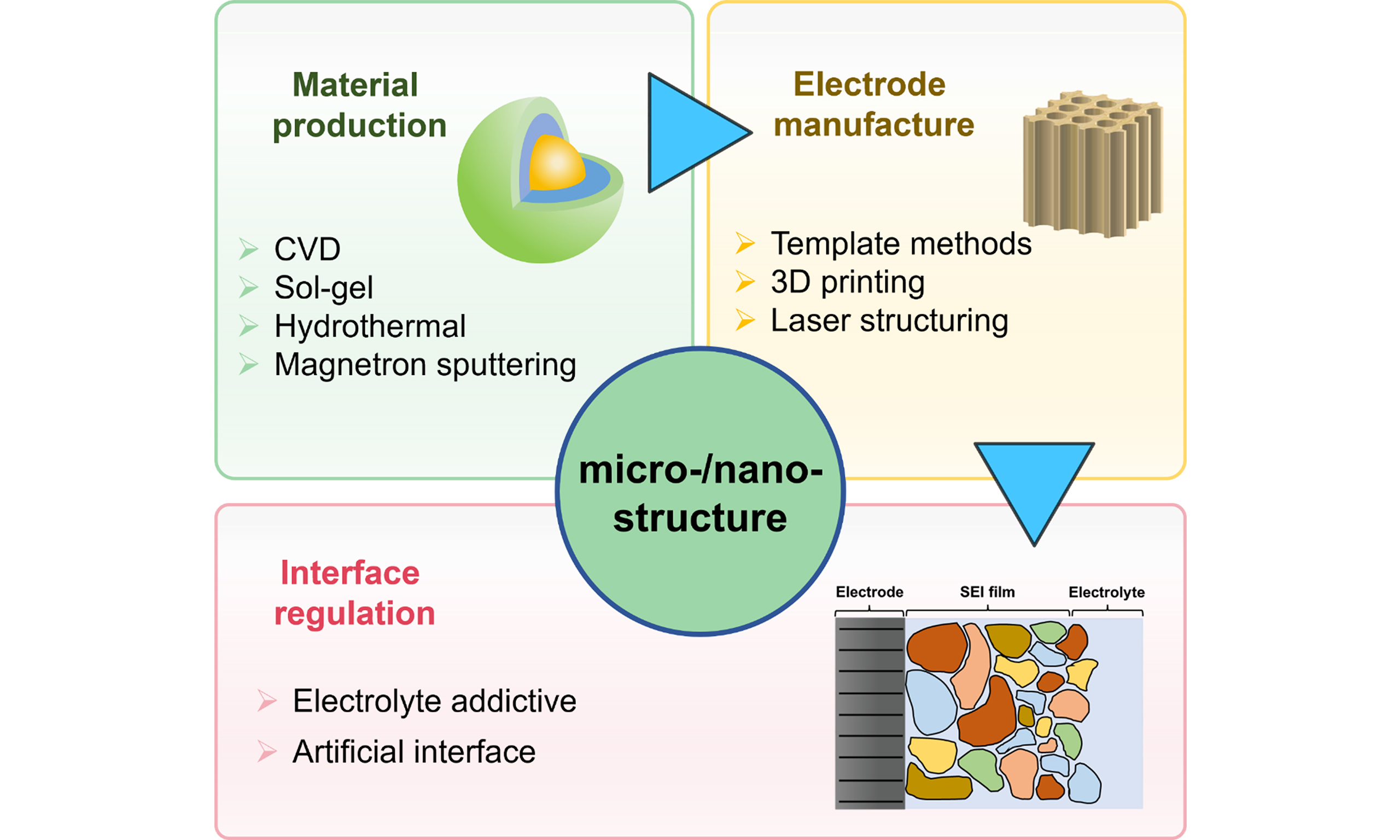
Nanostructure engineering has been recognized as the most effective approach to enhance the utilization and reaction kinetics of electrode materials[16]; however, nanostructural materials suffer from several insurmountable limitations, including low tap density, limited scalability, intense side reactions induced by a large surface area. On the contrary, micrometer-sized particles possess improved structural stability and lessened interfacial reaction, which can compensate for the weaknesses of nanoparticles (NPs). In this sense, constructing micro-/nano-structure is expected to combine the advantages of both nanomaterials and micromaterials, thus being extensively employed in material production and electrode manufacture. In addition to the micro-/nano-electrodes, many recent works have recognized that by tuning the micro-/nano-structure, the electrode/electrolyte interfaces can be substantially reinforced, and the charge transfer resistance (Rct) can be significantly lowered[17,18]. For instance, Rajeev et al. employed the solid-state method to synthesize nanoscale monoclinic LiFeBO3 samples with carbon coatings[19]. Elango et al. combined templating and spark plasma sintering approaches to make thick binder-free electrodes with high porosity[20]. Jiang et al. developed gradient porosity architecture with through-hole carbon spheres to promote fast charging and low-temperature workable LIBs[21]. Evidently, as illustrated in Figure 1, micro-/nano-structures are of great importance in improving the electrochemical performance of electrode materials and electrode/electrolyte interfaces.
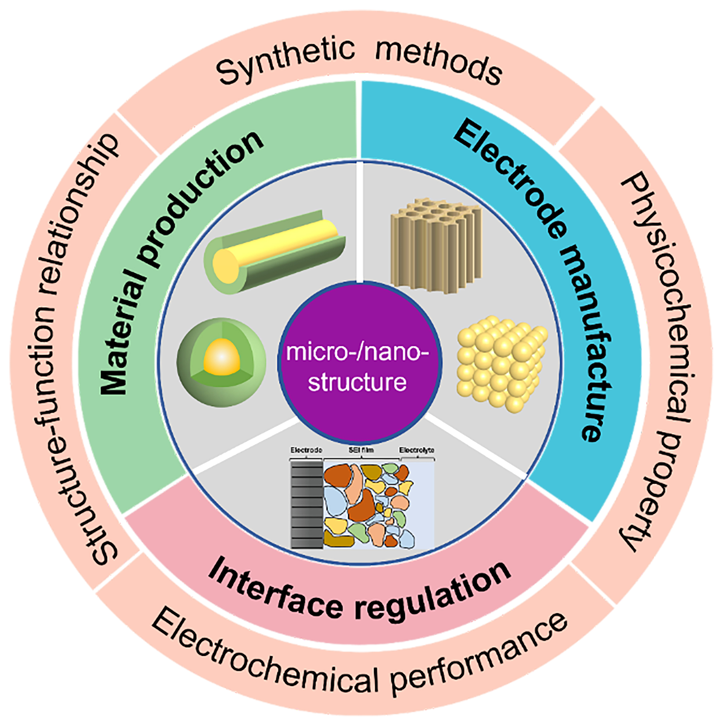
Figure 1. Schematic illustration of micro-/nano-structures for battery applications.
At present, there are several reviews on micro-/nano-structures, with the majority focusing on the introduction of various kinds of electrode materials with micro-/nano-structures[22-25], and some discussing the unique features of microstructures and nanostructures[26]. However, there are relatively few reviews discussing structuring strategies and techniques for micro-/nano-structures. Aiming to promote the widespread application of micro-/nano-structures in alkaline metal-ion batteries, we summarize the latest progress and different techniques of various hierarchical strategies in this work. The profits of micro-/nano-structural design in materials, electrodes, and interfaces are shown in Figure 2. Designing active materials (AMs) with micro-/nano-structures depends significantly on synthetic methods that can control hierarchical structure and particle size. Common approaches such as chemical vapor deposition (CVD), sol-gel method, hydrothermal synthesis, and magnetron sputtering are adopted to achieve enhanced electrochemical performance, structural/mechanical stability, and reduced ion diffusion paths. The research of micro-/nano-electrode manufacture mainly focused on the tuning of the ordered pore structure in order to facilitate fast ion diffusion in thick electrodes, thereby balancing the contradiction between energy density and power density. Additionally, electrodes need to meet requirements for lower tortuosity, regulated porosity, and enhanced structural controllability. The related structuring strategies can be implemented during or after the electrode manufacturing process, such as three-dimensional (3D) printing, laser structuring, template method, etc., among which template methods include solid templating, wood templating, and ice templating. In the following sections, important efforts to construct micro-/nano-structures in alkaline metal-ion batteries are summarized and discussed in detail.
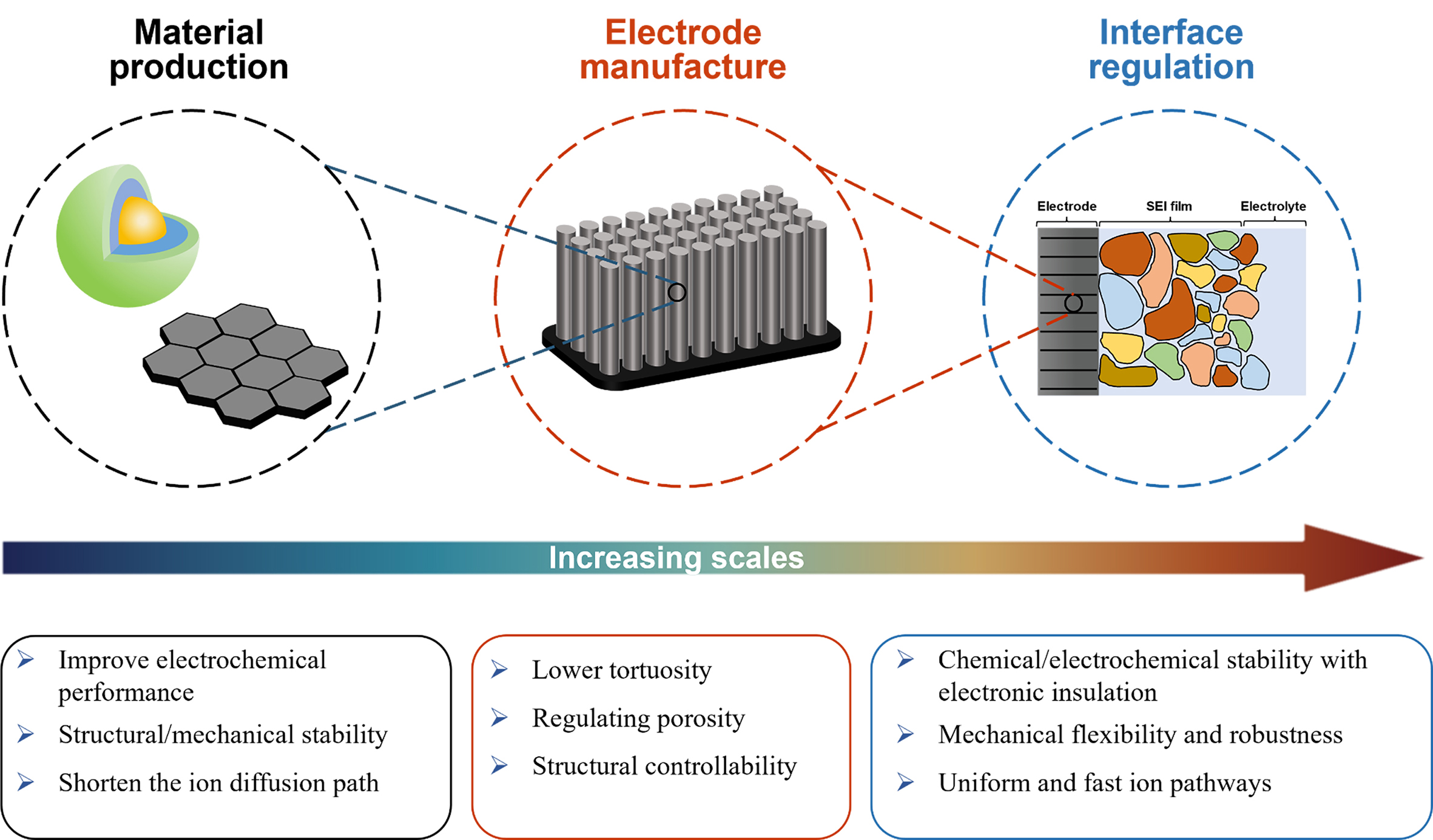
Figure 2. The profits of micro-/nano-structural design in materials, electrodes, and interfaces.
MATERIALS PRODUCTION
Nanoengineering can effectively improve the performance of AMs in terms of a high specific capacity, excellent rate performance and stable cycle life. Different structures have various advantages. Low-dimensional nanometer structural materials are conducive to accelerating electron/ion transport, and 3D nanostructured materials are beneficial for improving structural stability and inhibiting agglomeration[22]. Further, to enhance the performance of AMs and mitigate material phase transitions, the research of materials coating technology is very meaningful. The strategic design of coatings can effectively prevent direct contact between AMs and the electrolyte, while also providing multiple benefits. These include buffering volume changes, enhancing the electronic/ionic conductivity, clearing the intermediate of the electrochemical reaction, and stabilizing the electrode/electrolyte interface[23].
According to the morphology of nanostructure materials, they can be divided into spherical structures (NPs[24], spheres[25], etc.), linear structures (nanorods[26], nanotubes[27], nanofibers[28], etc.), sheet structures (nanosheets[29], nanowalls[30], etc.), and special structures (nanorings[31], nanocubic[32], etc.), as shown in Figure 3A. At present, there are many methods to construct nano-/micro- structures, including CVD[33-35], sol-gel method[36-39], hydrothermal synthesis[40-42], sputtering[43-46], atomic layer deposition[47], electrostatic spray deposition[48], pulsed laser deposition[49] and microemulsion[50].
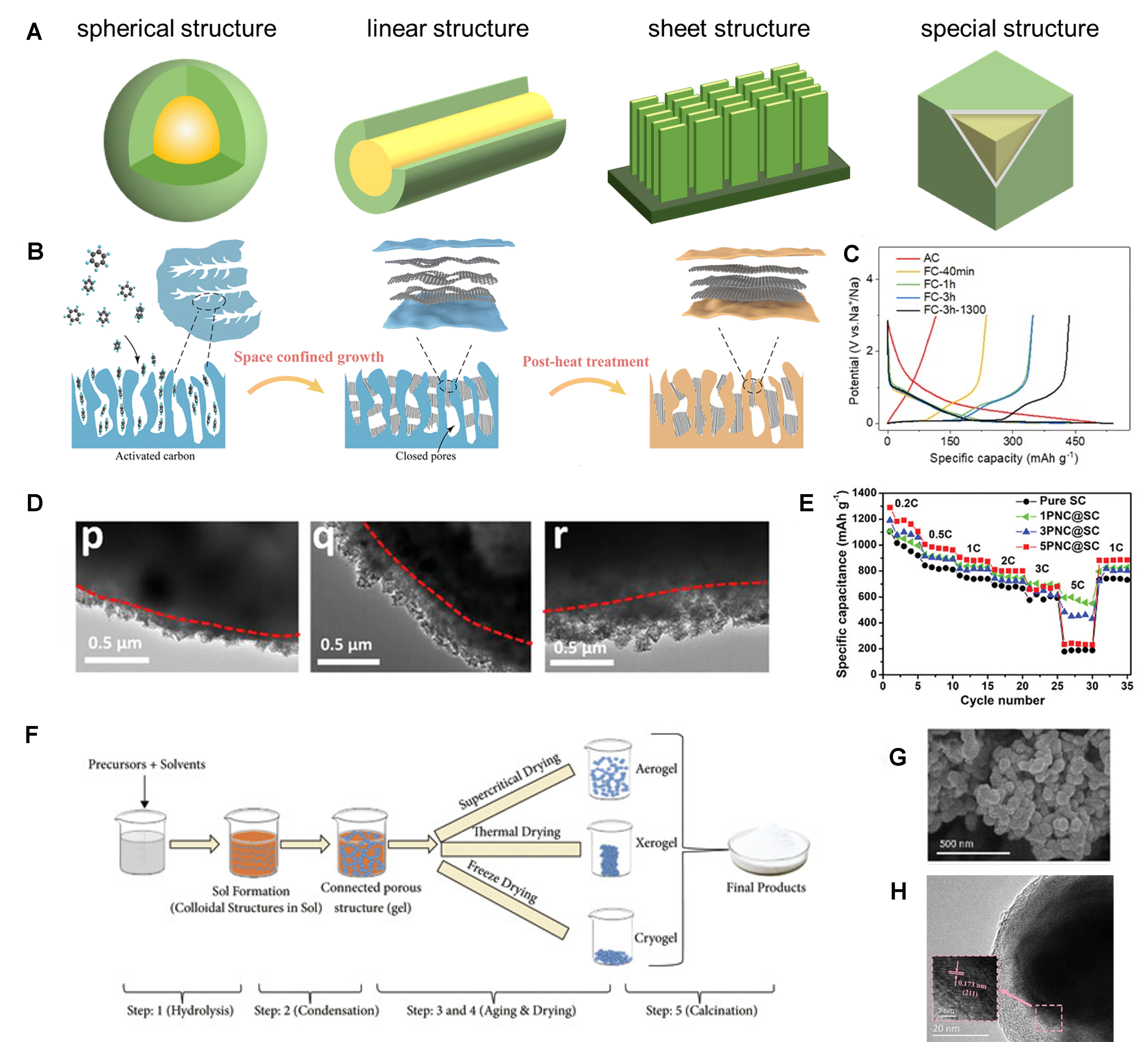
Figure 3. (A) Schematic representation of four nanostructures; (B) Schematic illustration of the synthetic procedure of the FC samples; (C) Initial charge and discharge curves of AC and FC electrodes in sodium-ion battery with a current density of 20 mA·g-1[34]. Copyright 2023, RSC; (D) TEM images of the core-shell PNC@SC particles with different loadings of PNC; (E) Comparison of rate performance of pure SC, 1PNC@SC, 3PNC@SC and 5PNC@SC-based electrodes[35]. Copyright 2023, Wiley-VCH; (F) Schematic of different stages of sol-gel process[37]. Copyright 2021, The authors, published by Wiley-VCH; (G)SEM and (H) HR-TEM images of Si@MoO2@C[39]. Copyright 2020, Wiley-VCH. AC: Activated carbon; FC: filling carbon; PNC: porous nano-carbon; SC: sulfur/carbon composite secondary particles; SEM: scanning electron microscopy; TEM: transmission electron microscopy; HR-TEM: high-resolution transmission electron microscopy.
CVD
CVD is a process that converts gaseous precursors into solid nano-coatings through gas-phase chemical reactions, typically forming the required material layer on the AM surface. The dense and uniform coatings prepared by CVD can enhance the mechanical stability and electrode stability of AMs. CVD enables the precise regulation of coating thickness and uniformity[33]. Chen et al. proposed a space-confined CVD (SC-CVD) method to prepare filling carbon (FC) materials, as shown in Figure 3B. By changing the residence time and employing subsequent heat treatment, the graphite-like carbon domain and micropore size of FC materials can be easily controlled. As shown in Figure 3C, the plateau capacities of FC electrodes increase with the residence time, which is attributed to the growth of graphite-like domains and the creation of closed pores within the carbon material[34].
During the CVD process, it is necessary to strictly control the thickness of the coating, as different thicknesses have different impacts on the material properties. Feng et al. proposed a micro-adhesion guided nano-vapor deposition (MAG-NVD) technique and found that coatings of different thicknesses have varying effects on the material’s rate capability and specific capacity[35]. The transmission electron microscopy (TEM) images in Figure 3D illustrate the sulfur/carbon composite secondary particles coated with porous nano-carbon(PNC@SC) particles with different thickness loadings of PNC. At low current densities, the specific capacity is predominantly affected by the shuttle effect; therefore, AMs with stronger LiPS capture ability, such as 5PNC@SC, can provide higher capacity. However, at high current densities, the specific capacity is primarily determined by the charge transfer capacity, so AMs with greater charge transfer capacity, such as 1PNC@SC, have better performance [Figure 3E][35].
Sol-gel method
The principle of the sol-gel method is as follows: dissolve the materials in the alcohol solvent, form a sol system through hydrolysis and condensation, then polymerize between the sols to form a gel with a 3D spatial structure, and finally remove the gel to obtain a dense final product[36]. The process of sol-gel is shown in Figure 3F[37]. The product prepared by the sol-gel method has the advantages of high sample purity, small particle size and uniformity[38], which can effectively improve the specific surface area and uniformity of electrode materials, thereby enhancing the conductivity, energy storage efficiency and cycle stability of the battery. The sol-gel method has attracted significant interest from researchers as a feasible method for achieving both effective coating and uniform distribution of particles. Huang et al. designed a core-dual shell Si@MoO2@C utilizing the sol-gel method combined with the solvent evaporation technique. Figure 3G and H shows the scanning electron microscopy (SEM) and high-resolution TEM (HR-TEM) images of Si@MoO2@C, respectively. The results show that the use of the sol-gel method results in a uniformly distributed coating. The obtained material has the advantages of low resistance, volume expansion restriction, and high electrical conductivity. The Si@MoO2@C anode exhibits a high initial coulombic efficiency (ICE) of approximately 80.3%, and a good specific capacity of about 1,172 mAh·g-1 after 100 cycles at 1 A·g-1 with a capacity retention of around 90.1% compared to the second cycle[39].
Hydrothermal synthesis
Hydrothermal synthesis is a versatile technique that allows a high level of precision in the morphology and particle size of the AM, facilitating the formation of porous nanomaterials and high-purity nanostructured materials (including 1D, 2D, 3D and layered structures)[40]. Chen et al. prepared practical SiMP@C-GN anodes with low specific surface area and high tap density using a defect-tolerant design of the 3C architecture to accommodate the volume variation of the microparticulate Si (SiMP) during the cycle. As shown in Figure 4A, during the hydrothermal process, SiMP@C is intricately woven into the interconnected graphene hydrogels, which are subsequently contracted so that the compact graphene network firmly bonds to the surface of SiMP@C in Figure 4B. The stress-strain curves in Figure 4C show that with increased capillary shrinkage and complete densification, the mechanical properties are significantly improved, reaching a compressive strength of approximately 121 MPa. With a high mass loading, the SiMP@C-GN/NCM811 full-cell achieves an exceptionally high volumetric energy density of 1,048 Wh·L-1[41].
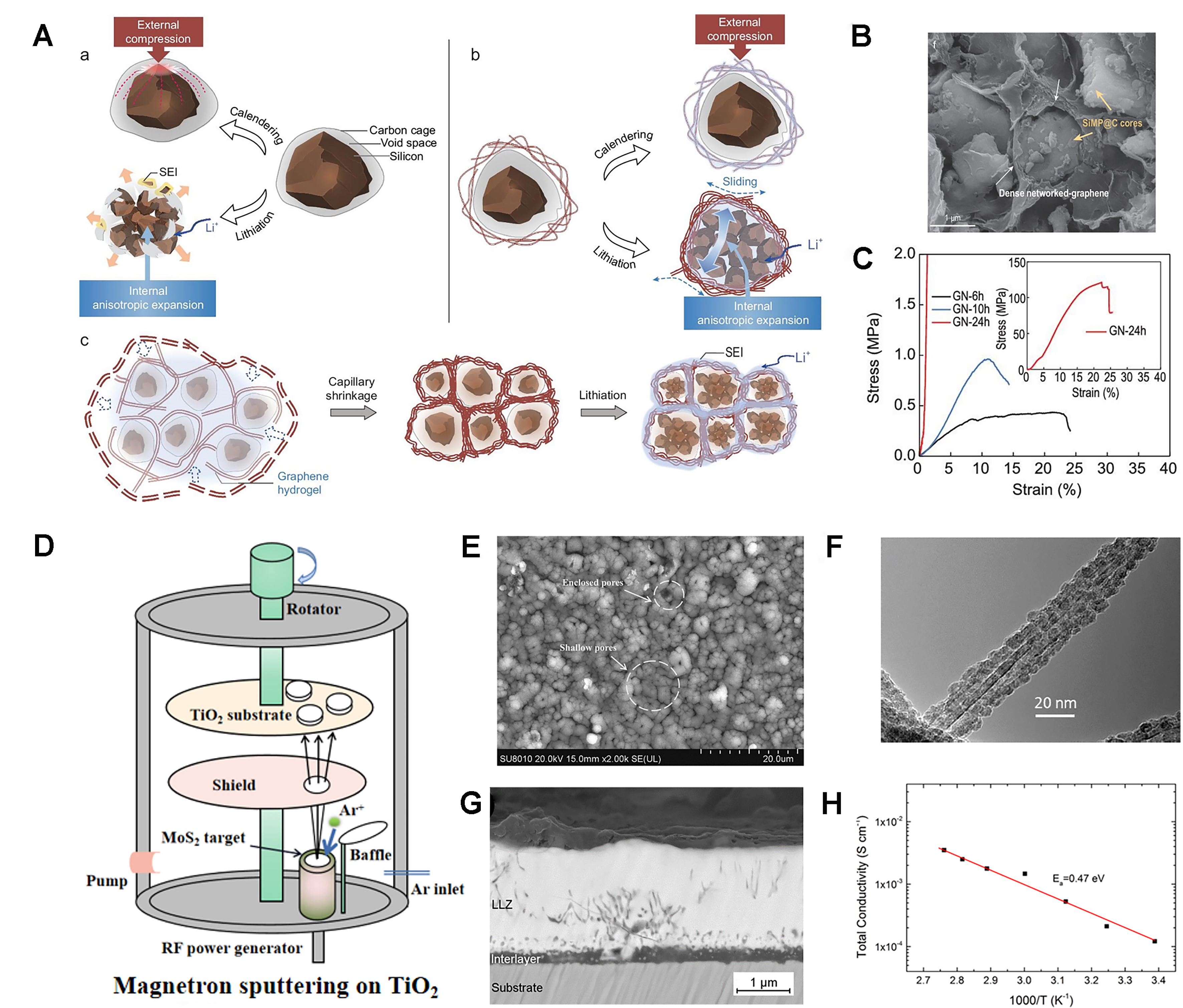
Figure 4. (A) Ductile carbon cage with voids and a cellular graphene network for Si microparticles; (B) SEM image of SiMP@C-GN; (C) Stress-strain curves of the compression of GN-24, -10 and -6 h cylinders[42]. Copyright 2021, The authors, published by Oxford University Press; (D) Preparation process of the TiO2/MoS2 composite film; (E) Surface morphology of the TiO2/MoS2 composite film after 100 cycles.[43] Copyright 2022, Elsevier; (F) TEM image of Fe3O4-CNT[44]. Copyright 2013, ACS; (G) BSE image of the thin films deposited at 700 °C; (H) Li-ion conductivity σ in dependence of temperature T[45]. Copyright 2016, Elsevier. SiMP: Silicon microparticles; C-GN: carbon-graphene network; SEM: scanning electron microscopy; GN: graphene network; TEM: transmission electron microscopy; CNT: carbon nanotube; BSE: backscattered electron; Li-ion: lithium-ion; σ: Ionic Conductivity; T: temperature; SEI: solid electrolyte interphase.
During the hydrothermal process, the morphology and size of AMs are influenced by the hydrothermal conditions. To investigate this phenomenon, Lakienko et al. studied the impact of hydrothermal carbonization parameters on hard carbon characteristics. By adjusting the raw material solution, the duration and the temperature of hydrothermal treatment, hard carbon was obtained with the optimal ICE. Subsequently, they assembled full coin cells using the Na3(VO)2(PO4)2F and hard carbon obtained from a
Magnetron sputtering
Magnetron sputtering, a quintessential method of physical vapor deposition, boasts several benefits, such as simple equipment configuration, straightforward operation, extensive coating capability and excellent adhesion between the substrates and sputtered materials. As magnetron sputtering technologyadvances, it has gradually obtained more advantages such as rapid deposition rates, low temperature and minimal material damage[51].
Magnetron sputtering is extensively employed for the fabrication of thin film electrodes. Sun et al. utilized magnetron sputtering to deposit MoS2 onto the TiO2 layer, as shown in Figure 4D. The resulting composite film has a uniform deposition of MoS2 and a high porosity, and Figure 4E shows its surface morphologies after 100 cycles. The film shows no significant changes, with the exception of some minor and enclosed pores resulting from localized mechanical stress, indicating that the composite film has excellent structural stability and is capable of enduring volume fluctuations throughout the lithiation-delithiation cycles[43].
Throughout the deposition process, various factors, including temperature, duration, and substrate, can influence the physical and electrochemical characteristics of the AM. Lobe et al. successfully prepared the device cubic garnet structure Li7La3Zr2O12 (LLZ) by using magnetron sputtering. By adjusting the deposition temperature, it was found that cubic LLZ began to form in large quantities at 650 °C, and became the main phase at 700 and 800 °C, with only a small number of impurities, which were found to be oxide interlayers. Figure 4G is the backscattered electron (BSE) image of the thin films deposited at 700 °C. In-plane total lithium-ion conductivity was measured to be 1.2 × 10⁻⁴ S·cm-1 at room temperature, and the activation energy was determined to be 0.47 eV [Figure 4H][45]. Bohne et al. investigated how various substrates affect the preferred orientation of LCO. They found that annealed 400 nm thick LCO films sputtered on bare and oxidized silicon wafers achieved a preferred (101) orientation, which is beneficial for realizing high power rates[46].
ELECTRODE MANUFACTURE
An electrode typically comprises AMs, conductive carbon and binder. In addition to the preparation of AMs, the development strategy for high-performance batteries based on electrodes also includes electrode manufacture or optimization of electrode structure, which refers to improving the performance of the battery without changing the chemical properties of the electrode. The design of electrode structure involves optimizing numerous parameters, such as porosity, thickness, pore size and particle size; the effect of these variations on battery performance is quite complex[52-54]. Increasing the thickness of the electrode can improve energy density, but it results in longer ion transport channels, higher ohmic resistance and poorer mechanical properties of the electrode[55-57]. A higher porosity rate is beneficial for ion transport, electrode wetting and electrolyte penetration, but it can result in reduced energy density, lower electrical conductivity, and mechanical strength[58-61]. Although often overlooked, pore sizes also influence performance. Smaller pore sizes are better for ion transport, while larger pore sizes are conducive to electrolyte infiltration[62,63]. Smaller particle sizes can enhance mass transfer rates and affect mechanical properties, but it is easy to produce side reactions[64,65]. Balancing these factors is essential for developing high-performance batteries that meet specific application requirements. Currently, there are many methods for electrode manufacture, and the next content will mainly introduce the template method, 3D printing and laser structuring.
Template method
Solid templating
Specific solid salts serve as templates to facilitate the production of nanostructured electrode materials, which commonly include 2D nanosheets, 3D networks, and porous nanostructures. Compared with conventional hard templates, inorganic salts do not require intricate pretreatment or surface modification procedures. Besides, they have the advantages of high mechanical strength, easy removal, good reuse and low cost[66]. The most widely studied inorganic salts include Na2SO4 and NaCl, and the schematic diagrams of solid templating manufacturing processes are shown in Figure 5A. Jang et al. used the Na2SO4 template to synthesize ferrite/carbon hybrid nanosheets, and Figure 5B shows its TEM image. It can be seen that the size and shape are uniform, and ferrite is assembled in highly ordered two-dimensional carbon nanosheets. When used in LIBs, after the cycling stabilizes, the capacity can be maintained at about 600 mAh·g-1[67].
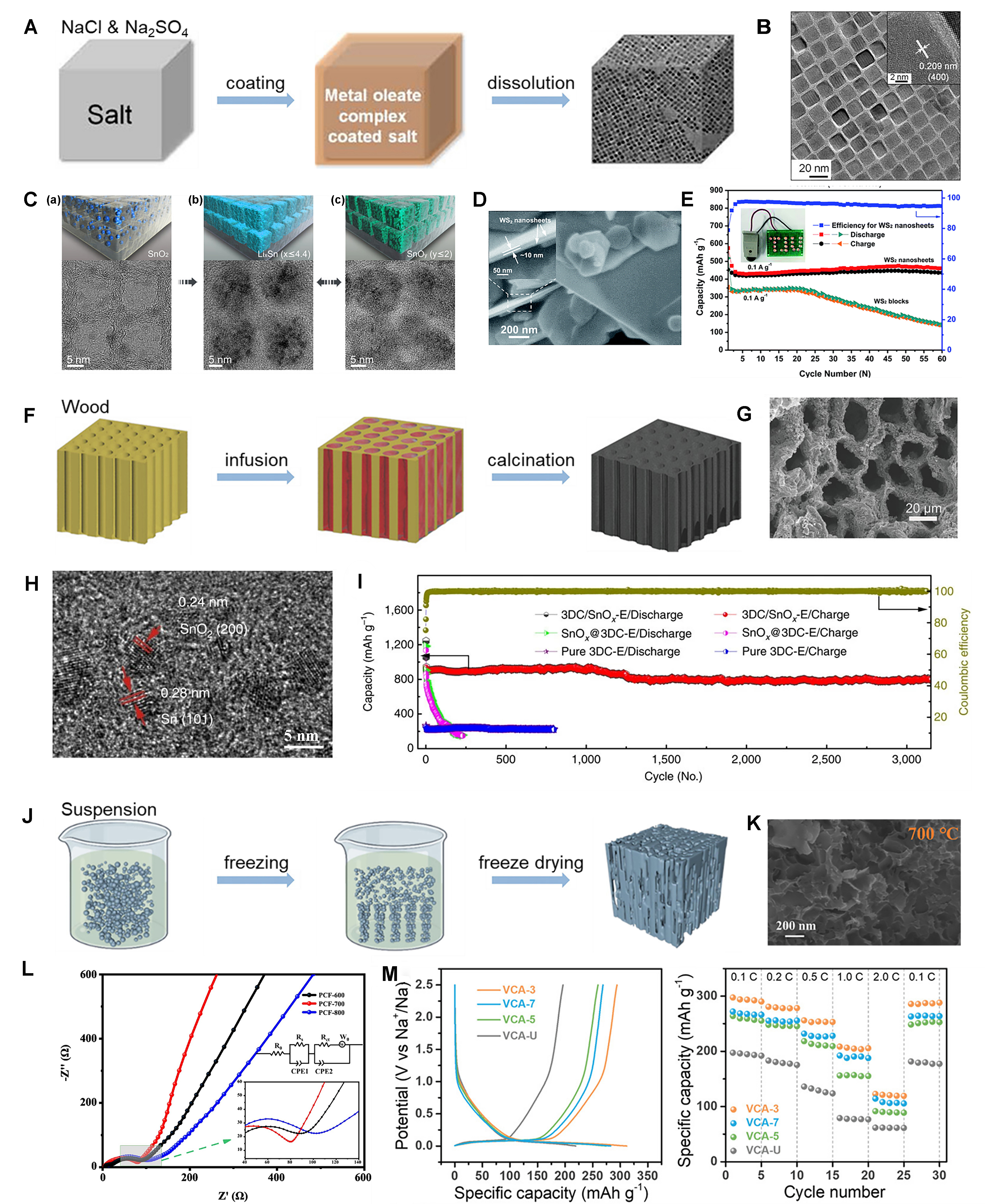
Figure 5. (A) Schematic diagrams of the salt templating manufacturing process; (B) TEM image of ferrite/carbon nanosheets[70]. Copyright, 2012, ACS; (C) Schematics of the morphology of SnO2 NPs and SnO2-based active material structure in the carbon cells (top), and TEM images of hybrid cellular nanosheets (bottom) before cycling (a), after lithiation (b), and after delithiation (c)[68]. Copyright 2015, ACS; (D) SEM images of WS2 nanosheets; (E) Cycle performance of the electrodes of WS2 nanosheets and WS2 blocks at a current density at 0.1 A·g-1[69]. Copyright 2016, RSC; (F) Schematic diagrams of wood templating manufacturing process; (G) The SEM image of the top view of LCO-2 electrode[71]. Copyright 2018, Wiley-VCH; (H) HR-TEM image of the 3DC/SnOx-E; (I) Cycle performance of the anodes of various materials at 625 mA·g-1[72]. Copyright 2016, The authors; (J) Schematic diagrams of ice templating manufacturing process[54]. Copyright 2022, The Authors, Published by Elsevier; (K) The SEM image of PCF-700; (L) Electrochemical impedance spectra of the electrodes for PCFs[76]. Copyright 2023, Elsevier; (M) Galvanostatic charge-discharge profiles of the second cycle and rate capability at various current densities from 0.1C to 2.0C[77]. Copyright 2022, The Authors, Published by Wiley‐VCH. TEM: Transmission electron microscopy; NPs: nanoparticles; SEM: scanning electron microscopy; LCO: layered cobalt oxide; HR-TEM: high-resolution transmission electron microscopy; 3DC: three-dimensional carbon; PCFs: porous carbon frameworks; ACS: American Chemical Society; RSC: Royal Society of Chemistry.
Wood templating
The wood has a unique anisotropic structure with a large number of longitudinal micro-channels for the transport of water and nutrients between the roots and the tree crown[70]. Inspired by this, natural wood was used to prepare electrodes with directional microchannels to reduce the meandering of pathways to enhance electrolyte diffusion and decrease the transmission distance for ions within the electrodes. Lu et al. synthesized LCO cathodes through a sol-gel vacuum infusion and calcination process [Figure 5F]. The wood chips are soaked in the electrode material sol under vacuum, and the solvent is kept at 72 °C to evaporate and the gel in the wood template microchannel is obtained. Then, the wood template is removed by high-temperature sintering and the LCO electrode is obtained, which provides a high area capacity reaching up to 22.7 mAh·cm-2. Figure 5G shows the SEM image of the LCO electrode[71]. Zhu et al. used plant roots to absorb metal salt solution (such as SnCl2 for 3DC/SnOx), and metal salt is absorbed by stems, branches and other parts of plants, followed by calcination at elevated temperatures in an argon environment to fabricate 3DC/MOx composite materials. The HR-TEM image of the 3DC/SnOx-E is depicted in Figure 5H. The 3DC/SnOx displayed a reversible capacity of 802 mAh·g-1 for over 3,000 cycles at 625 mA·g-1, as shown in Figure 5I[72].
Ice templating
Ice templating, alternatively known as freeze casting, is a simple processing method for creating porous materials[73]. One of the most widely used is the directional ice template (DIT). The process begins by mixing electrode materials with solvents (such as water, tert-butanol, liquid carbon dioxide, etc.) to form an electrode slurry. A temperature gradient is then applied to freeze the solvent, resulting in the formation of directional ice crystals. The solute is separated into the spaces between the ice crystals[74]. Afterward, the ice crystals sublimate, leaving behind pore channels [Figure 5J][74]. Huang et al. utilized ice templating to fabricate 600 μm thick cathodes used in solid-state lithium metal batteries (SSLMB), and the SSLMB full cells demonstrated a gravimetric capacity close to the theoretical limit of 199 mAh·g-1 and an exceptional areal capacity of 16.7 mAh·cm-2 at 0.05C[75]. Shi et al. utilized ice templates combined with carbonization strategies to construct a unique 3D porous carbon framework (PCF). As shown in Figure 5K, the TEM images of PCF-700 reveal that the nanosheets have formed an interconnected 3D PCF with many O-rich functional groups connected. Figure 5L is the electrochemical impedance spectra of the electrodes for PCFs, and PCF-700 clearly exhibits the lowest interphase contact resistance (Rs) and Rct values, indicating that the PCF-700 anode offers superior electronic conductivity and lithium-ion transfer properties. This leads to enhanced electrochemical performance[76]. Wang et al. developed a controllable unidirectional ice template strategy for the preparation of vertically aligned carbon aerogel (VCA) anodes, which has the advantages of fast ion diffusion, small volume change and more electrochemical active sites. A series of VCAs is obtained by adjusting the cooling rate of the suspension. Figure 5M shows the charge-discharge curve and rate performance of VCA when used for SIBs. It can be seen that VCA-3 exhibits excellent rate performance and reversible capacity with 298 mAh·g-1 at 0.1C[77].
The template method can improve the controllability of the electrode structure, including porosity and pore size. Despite some challenges remaining, such as the fact that solid templating typically results in pores with random distributions, and wood templating struggles with precisely managing porosity and pore size, both techniques face limitations in architectural control. Ice templating can create straight channels and permit the regulation of porosity and pore size, which are more controllable than the first two. Regarding sustainability, ice templating is better, and it does not need to add organic solvents. Wood templating can be moderately sustainable if no additional organic solvents or formwork are applied. Salt templating is less sustainable due to the additional salt particles used in the process. The scalability of different methods varies greatly; the scalability of salt templating is high, while wood templating and ice templating both suffer from relatively low scalability, which is due to the long growth cycle of wood and the limited equipment of ice templating.
3D printing
3D printing, or additive manufacturing, is a technology that involves creating objects layer by layer using computer-guided processes. Its core concept is to translate the electronic model of a design directly into a physical object, offering significant adjustability. This allows for the adaptable design and production of electrodes featuring intricate structures[78]. Additionally, it provides advantages such as environmental protection and low cost.
Direct ink writing
Direct ink writing (DIW) is a typical type of material extrusion process. It is the most prevalently employed approach for battery production through 3D printing due to its benefits of cost-effectiveness, user-friendliness, material versatility and maskless process[79]. The resolution of the material depends on the resolution of the nozzle[80]. In this method, the configured ink is sprayed directly on the platform using the nozzle, layer by layer, in accordance with the set pattern. As shown in Figure 6A, Park et al. successfully prepared a thick (~2 mm) graphite electrode using 3D printing technology and degreasing/sintering process. The electrode columns were closely arranged, devoid of structural flaws such as warping, delamination, or misaligned layers, and their porosity (~58%) is higher than that of traditional slurry casting electrodes (about 30%). Figure 6B displays the SEM images of the 3D graphite electrode. The 3D graphite electrode, measuring 1 mm in thickness, exhibited specific capacities of 393.8 mAh·g-1, equating to areal capacities of
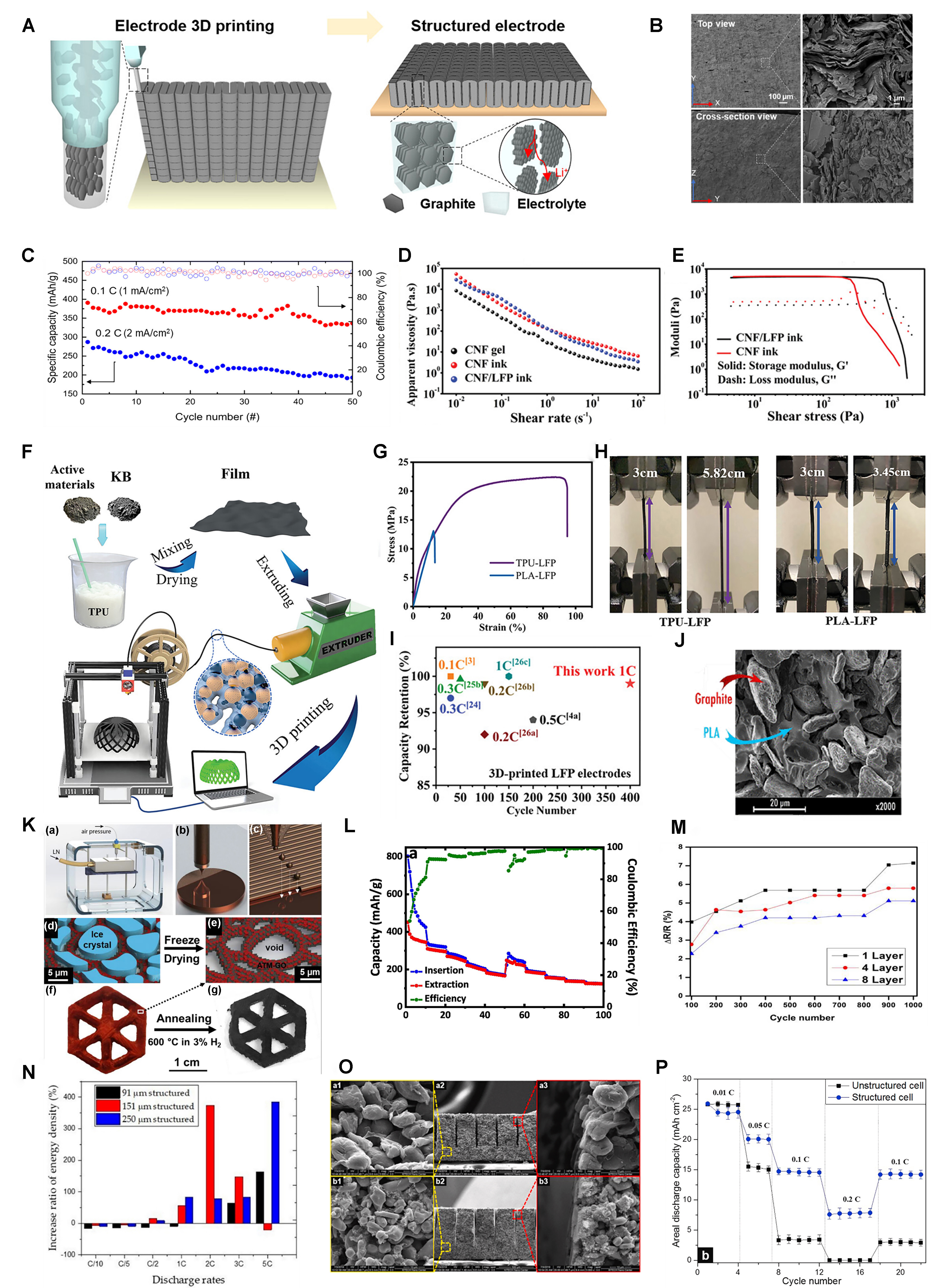
Figure 6. (A) Schematic of structured electrode additive manufacturing for 3D graphite thick electrode with an out-of-plane aligned architecture; (B) The SEM image of the 3D graphite electrode; (C) Cycle performance of 3D graphite electrodes at 0.1C and 0.2C[82]. Copyright 2022, ACS; (D) Apparent viscosity as a function of shear rate for pristine CNF gel, CNF ink and CNF/LFP ink; (E) The storage modulus, G’, and loss modulus, G”, as a function of shear stress for CNF and CNF/LFP inks[83]. Copyright 2019, WILEY-VCH; (F) Schematic illustration of the fabrication process of the 3D-printed TPU-based electrodes; (G) Stress-strain curve of TPU-LFP and PLA-LFP filaments; (H) Optical photograph of TPU-LFP and PLA-LFP filaments during the tensile strength evaluation; (I) Capacity retention comparison of TPU-LFP with previously reported values[84]. Copyright 2023, Wiley-VCH; (J) Inner part of SEM images of the 40% PEGDME500 homogeneous filament sample[85]. Copyright 2018, ACS; (K) Schematic of 3D MoS2-rGO aerogel preparation diagram; (L) Rate performance of the MoS2-rGO aerogel at different current density values (100, 250, 500, 750, and 1,000 mA·g-1)[86]. Copyright 2019, The authors, published by Elsevier; (M) Change in resistance ΔR/R (%) with cycle number of different layers of printed graphene[87]. Copyright 2021, ACS; (N) The increase of volumetric energy density of cells with structured cathodes at different C-rates[55]. Copyright 2019, The authors, published by MDPI; (O) SEM images of (A) graphite anode and (B) LCO cathode; (a1 and b1) and (a3 and b3) are high-magnified images at unstructured and laser-structured regions, respectively, and (a2 and b2) are cross-section images; (P) Areal discharge capacity of the full cells considering electrode mass concerning current rates[90]. Copyright 2020, Elsevier. 3D: Three-dimensional; SEM: scanning electron microscopy; CNF: cellulose nanofiber; LFP: lithium iron phosphate; G’: storage modulus; G”: loss modulus; TPU: thermoplastic polyurethane; PLA: polylactic acid; PEGDME: poly(ethylene glycol) dimethyl ether; rGO: reduced graphene oxide; LCO: lithium cobalt oxide.
Fused deposition modeling
Fused deposition modeling (FDM) is mostly used to create intricate objects with little material waste. The polymer material is heated into a liquid form by the nozzle, extruded from the extruder head and solidified to form the model according to the designed procedure[78]. Frequently utilized polymers in FDM processes comprise polylactic acid (PLA), thermoplastic polyurethane (TPU), polymethyl methacrylate (PMMA), and so on. In the FDM process, the material used for printing needs to exhibit flowability at elevated temperatures and possess the capability to conduct heat effectively. Hu et al. developed 3D-printed electrodes based on TPU for the fabrication of LIBs, and the schematic illustration of the fabrication process is shown in Figure 6F. Mechanical property tests were conducted on the electrodes, as shown in Figure 6G and H. The tensile stress, tensile strain, and elongation rate of TPU-LFP are significantly better than PLA-LFP, indicating that the TPU-LFP electrode has better stress buffering performance. Using half cells to study the electrochemical performances, the capacity retention of TPU-LFP is 98.9% after 400 cycles, which is significantly superior to other LFP electrodes, as shown in Figure 6I[84]. Maurel et al. studied the effects of plasticizers on the 3D printing process and determined that the optimal content of plasticizers was 40% PEGDME500. Figure 6J illustrates the inner section of the SEM image from the 40% PEGDME500 uniform filament sample. The reversible capacity of the electrode was determined, with the AM achieving capacities of 200 mAh·g-1 at a current density of 18.6 mA·g-1 after six cycles[85].
Inkjet printing
Inkjet printing (IJP) is a technology that uses ink droplet deposition to draw the desired structural pattern by controlling the discharge of the droplet. Brown et al. fabricated the MoS2-reduced graphene oxide (rGO) aerogel by using IJP in combination with freeze casting, as shown in Figure 6K. The interconnected graphene network within these 3D aerogels has been discovered to significantly boost electrical conductivity and mechanical robustness while the large pores (~3-5 μm) promote the rapid transfer of ions. When used in SIBs, Figure 6L shows that during the initial ten cycles, the high specific capacity dropped from approximately 800 to 429 mAh·g-1 at a current density of 100 mA·g-1 due to reversible insertion of two Na and irreversible conversion of MoS+2 to metal Mo. However, at elevated current densities, during subsequent cycles, the conversion reactions diminish, and the stability notably improves[86]. Kushwaha et al. discovered that the electrical resistance of 3D-printed graphene films diminished as the number of printing cycles increased. The smallest change in resistance (~5%) of the graphene film with eight printed layers after 1,000 cycles shows its stability and durability, as shown in Figure 6M. Conversely, graphene films with one and four layers exhibited relatively high resistance changes, which is due to the lack of uniformity and continuity within the film, as well as inadequate contact between the layers. Despite these issues, the graphene film still displayed a substantial reversible lithium storage capacity of approximately 942 mAh·g-1 at a rate of 0.1C[87].
3D printing is highly tuneable, allowing the flexibility to design and manufacture electrodes with fine structures. Regarding resolution, IJP is better, followed by DIW, and FDM has a lower print resolution. DIW can be printed directly on almost any surface, but the rheological properties of the ink are strict, which limits its application. FDM can be printed quickly; the inadequate electrical conductivity of plastic filaments and the restricted range of raw materials available are viewed as the main constraints of FDM. IJP boasts excellent multi-material compatibility and efficient material usage, which has great advantages in printing various design patterns, but its printing speed is slow, the requirements for ink formulation are high, and the durability of the print head is poor.
Laser structuring
Laser structuring has been identified as a potent method for enhancing ion mobility and boosting the performance of LIBs[88]. Laser processing can generate 3D microstructures on the planar electrode such as grooves and holes. Obviously, the high temperature of the laser will lose part of the AM, resulting in a slight loss of battery capacity, but some studies have found that laser-structured batteries have better performance. For example, Pfleging et al. reported that the use of laser structures to generate capillary microstructures formed in the tape-cast electrode helped to increase the rate of infiltration of the electrolyte and improve its infiltration uniformity. Its cycle stability has been significantly enhanced. The laser-structured Li(NiMnCo)O2 (NMC) electrode maintains a capacity retention rate of approximately 90% after 1,000 cycles, while the capacity of the unstructured NMC electrode decreases rapidly when the cycle number is up to 100[89].
To enhance the precision of laser structuring, several critical parameters must be adjusted, such as pulse energy, pulse duration, repetition rate, scan speed and repetition number[54]. Zhu et al. found that the adjustment of slot spacing (200-600 μm) significantly affected the battery’s magnification performance, and the magnification ability becomes increasingly pronounced as both current magnification and electrode thickness (90, 150, and 250 μm) are increased, which is shown in Figure 6N[55]. Park et al. strictly controlled the parameter preparation of laser equipment to obtain ultra-thick lithium cobalt oxide (LCO, 700 μm) cathode and graphite anode (650 μm) for high-energy LIBs. SEM images of graphite anodes and LCO cathodes are shown in Figure 6O. Graphite and LCO exhibit no swelling or cracking, with materials evenly distributed without gaps. Additionally, the grooves created by laser structuring display a high degree of uniformity in shape and dimensions. The laser structuring improved the porosity of lithium ions, reduced the tortuous degree, and shortened the diffusion path, thus improving the performance. Figure 6P shows the influence of laser structuring on the capacity relative to the mass of the electrode. The capacity of laser-structured batteries was about 5% less than that of the untreated battery at 0.01C, which corresponds to the mass reduction directly related to the loss of capacity caused by laser ablation. Conversely, at a comparatively elevated current rate of 0.1C, the laser-structured cell exhibited a usable capacity that was five times greater than that of the unstructured cell[90].
INTERFACE REGULATION
The interface has always been the focus of research, and it plays an important role in realizing the rapid transmission of ions and avoiding electron conduction. Many reactions occur on the interface. The typical interface that forms on the negative electrode is referred to as the “solid electrolyte interphase (SEI)”, while the interface that forms on the positive electrode is known as the “cathode electrolyte interphase (CEI)”. Figure 7A depicts the schematic representation of interface formation before and after cycling. The native SEI/CEI has many inherent defects, such as uneven chemical composition[91], poor mechanical stability[92,93], inconsistent working conditions[94,95], and so on. Therefore, in order to obtain more excellent performance, researchers have made great efforts to obtain the ideal interface with the target characteristics, which should meet the requirements, including chemical and electrochemical stability coupled with electronic insulation, mechanical flexibility and strength, and uniform and rapid ion transport channels[96,97]. The strategy to achieve the ideal interface mainly involves improving the original interface structure by optimizing electrolyte formulation and designing artificial interfaces.
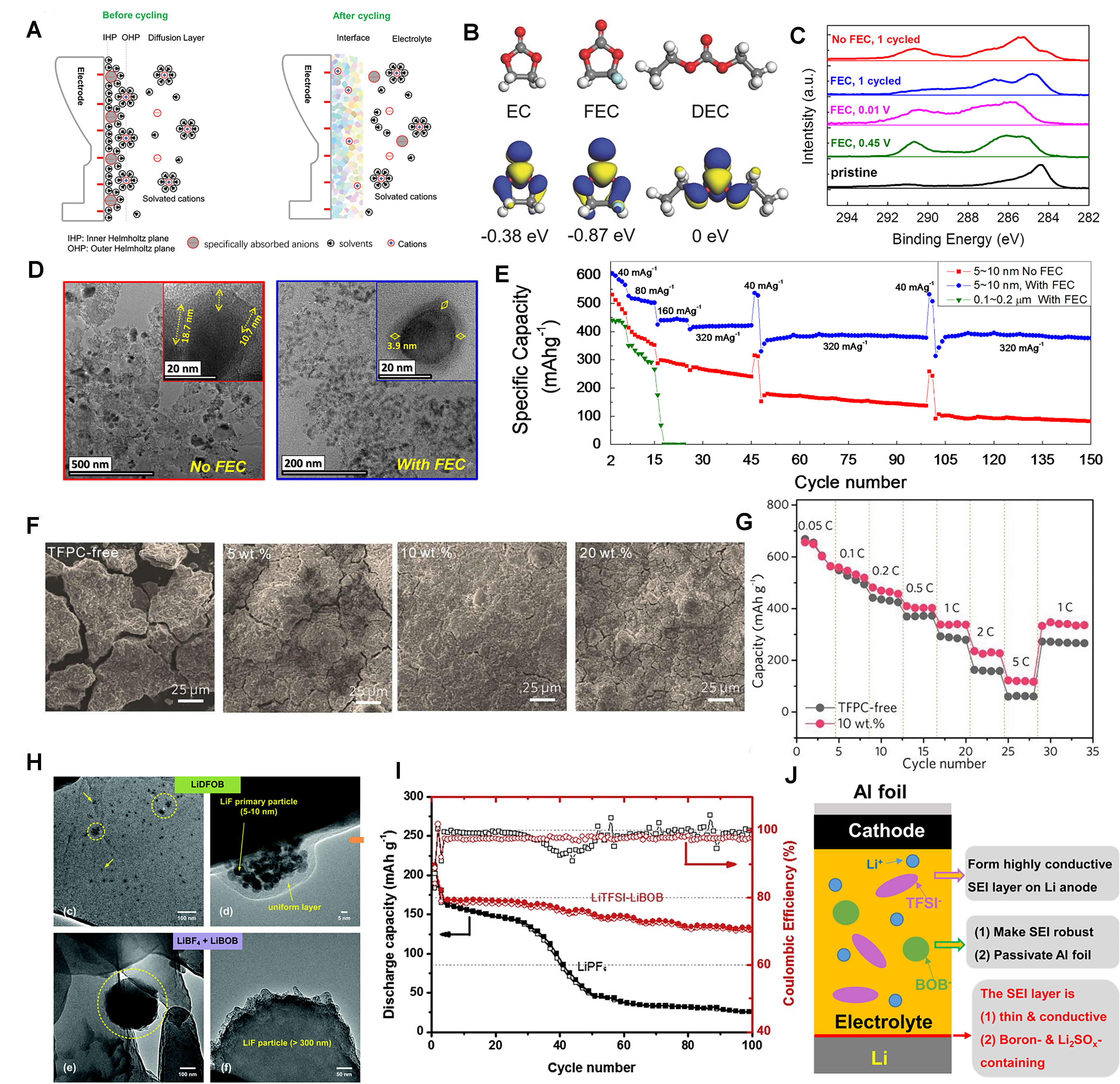
Figure 7. (A) The schematic diagram of the interface formation before and after cycling[97]. Copyright 2020, Wiley-VCH; (B) Molecular structure, visual LUMO and corresponding relative energy of EC, FEC, and DEC[100]. Copyright 2017, Wiley-VCH; (C) XPS C1s peaks of Sn electrode with FEC during 1st formation cycle; (D) HR-TEM images of cycled Sn electrode without FEC and with FEC additive; (E) Rate and cycle performance of Sn electrode without FEC and with FEC additive[101]. Copyright 2015, Elsevier; (F) SEM images of Si electrodes after cycling in the electrolytes containing 0, 5, 10, and 20 wt% TFPC for 50 cycles; (G) Rate capability of Si/C composite electrodes in the electrolytes without and with 10 wt% TFPC at various C rates[102]. Copyright 2019, Wiley-VCH; (H) TEM images of lithium plated from
Electrolyte additive
The properties of the interface can be directly controlled by modifying the chemical components within the electrolyte. The electrolyte additives should have a lower oxidation potential than the other components in the electrolyte, ensuring that they oxidize first at the electrode surface before the solvent molecules[98]. Additives significantly contribute to the performance of electrolytes by promoting film formation, enhancing electrochemical performance, and improving physical properties such as ionic conductivity, viscosity, and wettability. They also strengthen mechanical properties and enhance safety performance, such as reducing the flammability of the electrolyte and preventing overcharge[99]. We will further discuss the role of additives in micro- and nanoscale interface regulation, focusing on their form (solvent and salt).
Solvent
Fluoroethylene carbonate (FEC) is a common electrolyte additive, possessing a lower level of the lowest unoccupied molecular orbital (LUMO) at -0.87 eV compared to ethylene carbonate (EC) at -0.38 eV and diethyl carbonate (DEC) at 0 eV as shown in Figure 7B, preferentially reducing to LiF-rich SEI on the surface of lithium metal[100]. Eom et al. researched the nanoscale bare Sn LIB materials with FEC addition to affect its electrochemical and morphological properties. HR-TEM and X-ray photoelectron spectroscopy (XPS) analyses [Figure 7C] of the in situ electrochemical formation of the SEI revealed that FEC served as an effective oxidizing agent during the oxidation process, promoting the removal of SEI with carbon compounds that were highly oxidized and possessed high binding energy. Figure 7D shows the HR-TEM images comparing the cycled Sn electrode, one without FEC and the other with the addition of FEC. A high-quality SEI that is thin and possesses low resistance significantly enhances the rate performance and capacity retention of nano-sized bare Sn electrodes. As shown in Figure 7E, Sn electrodes exhibited no capacity decay at 320 mAh·g-1 up to and beyond 150 cycles, and especially in 150 cycles, it displayed a capacity that was 260% greater than that of a Sn electrode with a typical SEI formulation lacking FEC[101]. Trifluoropropylene carbonate (TFPC) is also a good film-forming additive. Hu et al. employed TFPC as an effective film-forming additive in high-performance silicon nanoparticle (SINP)-based and Si/C composite electrode electrolytes. TFPC is characterized by its low LUMO energy at -0.28 eV and high reduction potential of 2.05V and 1.89V. As can be seen from the SEM image in Figure 7F, the Si electrode cycled in the electrolyte with 0 and 5 wt% TFPC exhibited obvious cracks and an exceedingly thick SEI layer, as 20 wt% TFPC also showed tiny cracks and a slightly thicker SEI layer. Conversely, the Si electrode with 10 wt% TFPC demonstrated a remarkably smooth surface and a thin SEI layer. Therefore, the addition of 10 wt% TFPC can facilitate the development of a thin, uniform, and mechanically robust SEI film on the surface of Si. Figure 7G shows the ratio performance test of the Si/C electrode with or without TFPC electrolyte. It can be seen that 10 wt% TFPC-based electrolyte has higher reversible capacity under all current densities[102].
Salt
As a simple but effective method, several electrolyte additives, such as fluorine, borate[103], sulfite[104], and nitrates derivatives[105], have been introduced to adjust the composition of in situ SEI (form LiF, LiBxOy,
Jurng et al. believed that the nanostructure of the SEI, rather than its molecular composition, leads to a significant disparity in the cycling performance of the cells[103]. They used the common salts LiBF4, LiBOB and LiDFOB. These salts were incorporated into the carbonate solvent to prepare the electrolyte. The in situ surface analysis (XPS) showed that the LiBF4 + LiBOB electrolyte and the LiDFOB electrolyte had highly similar chemical composition on the surface film, and LiDFOB had the best electrochemical performance while LiBF4 + LiBOB electrolyte cycle lithium has a rapid performance decay. As shown in Figure 7H, the TEM analysis showed that LiDFOB electrolyte formed homogeneous nanostructured LiF particle films on the surface of lithium, while LiBF4+LiBOB electrolyte formed non-homogeneous films containing larger LiF particles. The incorporation of nanostructured LiF particles results in the creation of a consistent diffusion field gradient, thereby ensuring a uniform lithium deposition. Consequently, aside from the formation of a stable SEI from the LiDFOB electrolyte, the regulated formation of nanostructured LiF is pivotal in enhancing the plating/stripping efficiency of lithium metal anodes[103].
To address the limitations of single-salt systems, many researchers have adopted the dual-salt and multi-salt concepts that combine the complementary functions of different anionic chemistry to achieve better performance[106]. Xiang et al. mixed LiTFSI and LiBOB in a carbonate-based solvent to improve the charging capacity of lithium-metal batteries compared to LiPF6-based electrolytes. The cycle performance test results are shown in Figure 7I. At a current density of 1.50 mA·cm-2, after 100 cycles, the batteries used in the double-salt electrolyte can still provide a discharge capacity of 131 mAh·g-1, and the capacity retention rate is about 80%. In contrast, batteries with only LiPF6 electrolytes experienced a rapid decline in capacity, with a retention rate of just 15%[92]. As shown in Figure 7J, in this dual-salt system, LiTFSI is responsible for creating a highly conductive SEI layer made of lithium sulfonate to facilitate rapid charging, while LiBOB enhances the robustness and stability of the SEI throughout the cycling process. At the same time, LiBOB is also essential for the passivation of the Al collector during long-term battery operation[92]. The dual-salt system can benefit LIBs as well. Yang et al. used electrolytes containing LiPF6 and LiDFP in EC/DEC. By controlling the amount of LiDFP, the decrease of ionic conductivity of electrolytes can be slowed down. Finally, 1.1 M LiPF6 and 0.1 M LiDFP were determined as the optimal electrolyte ratio, which can improve the electrochemical performance of LIBs and establish a stable cathode interface to effectively inhibit the rise of impedance during battery aging and reduce the structural damage of cathode particles[107].
Manufacturing artificial interface
The method of designing an artificial interface has high flexibility. We can control the structure of artificial interfaces and adjust the composition to realize the design of a multilevel structure and multiple functions. Based on the high reactivity of lithium, various artificial interfaces can be prepared by using the chemical reaction of lithium and reagents, such as nitriding interface, fluorination interface, sulfurized interface, composite interface, etc. It is crucial to note that the reaction conditions need to be precisely adjusted, including temperature, reactant concentration and reaction duration. It is an important step to analyze the products at the interface, such as the compactness, the stability in the electrolyte, and the ionic diffusivity[97].
Nitriding interface
As a common additive, LiNO3 contributes to the nucleation and growth of metal lithium spheres[108]. However, the low solubility of LiNO3 in ester-based electrolytes significantly constrains its application. Therefore, Li et al. adopted a pretreatment method to construct a phosphating - nitriding interface through the reaction of lithium metal with PCl5-LiNO3 complex. The HR-TEM image [Figure 8A] shows that it mainly consists of inorganic Li3PO4, Li3N, and nanocrystalline LiCl. These components provide high ionic conductivity and robust mechanical stability, which are conducive to uniform lithium electrodeposition. The rapid ionic channel of the phosphating-nitriding (PN) layer is also evidenced by electrochemical impedance spectroscopy, which shows that the PN interface has the lowest interfacial resistance, approximately 10 Ω in the initial cycle, as depicted in Figure 8B. Due to the fast lithium-ion conductivity of Li3N and LiNxOy, coupled with the robust mechanical stability of inorganic NPs, it makes sense that the PN layer can bolster interface stability and equalize the Li-ion flux at the interface. Because of the uniform lithium deposition behavior of the PN-Li anode, excellent electrochemical cycling performance can be realized[109]. When using NCM cathodes and the N/P ratio reached 3.92, the full battery operated successfully through over 100 cycles, achieving a high coulombic efficiency (CE) of 99.8%, and a four-fold increase in battery life compared to naked Li/NCM batteries as shown in Figure 8C[109]. The same applies to the solid-state electrolyte.
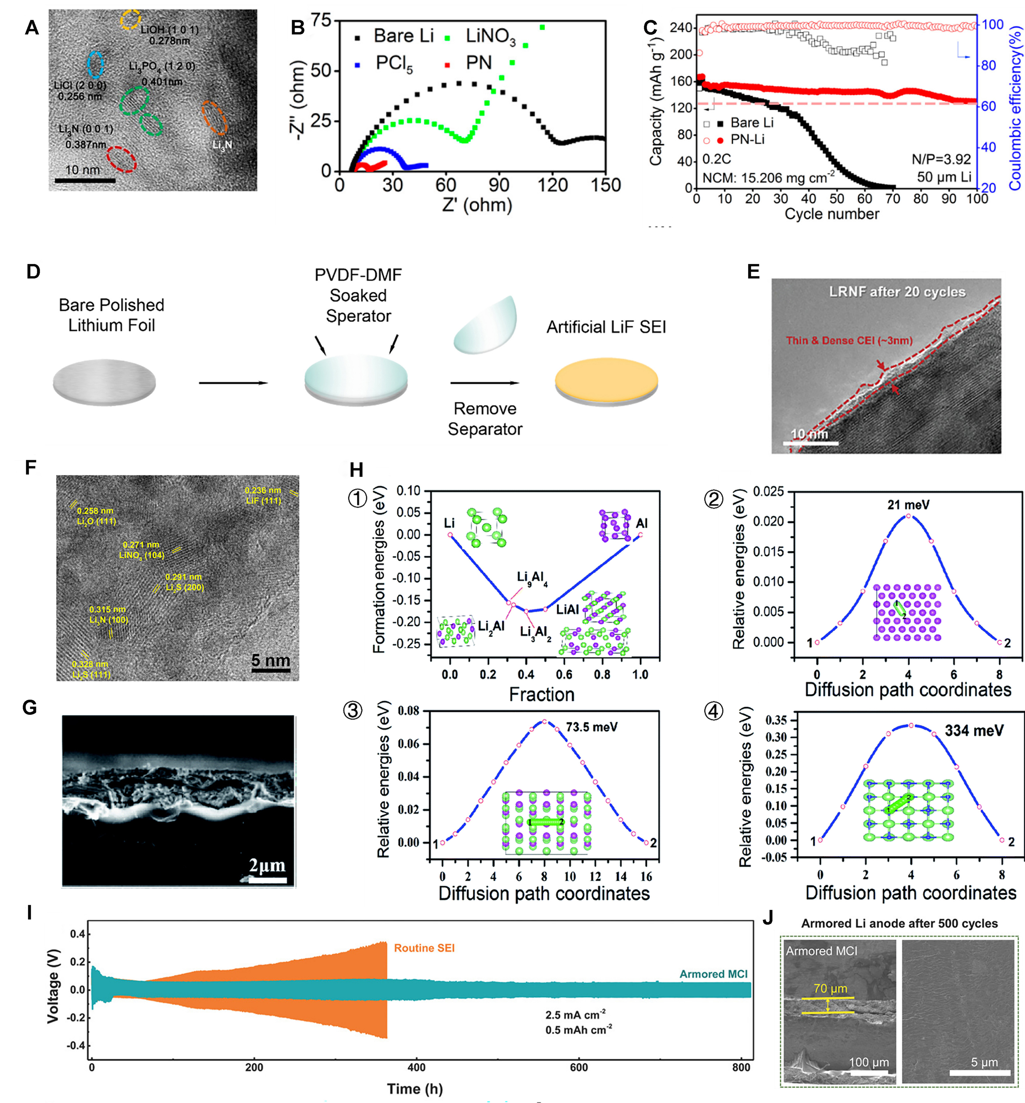
Figure 8. (A) HR-TEM image of PN interface; (B) Electrochemical impedance spectra of the Li anode treated by different materials; (C) Long-term cycle performance of Li/NCM523 full cells with mass loadings of 9.9 and 15.206 mg·cm-2[109]. Copyright 2020, ACS; (D) Illustration of the process for fabricating LiF-coated Li[113]. Copyright 2019, Elsevier; (E) HR-TEM images of LRNF after 20 cycles[114]. Copyright 2023, Wiley‐VCH; (F) A HR-TEM image of the sulfurized SEI[120]. Copyright 2017, Elsevier; (G) Cross-sectional view of SEM images of the lithium anode AlF3@Li; (H) (1) DFT calculated formation energies of the Li-Al binary alloys; energy variations of Li ion diffusion on (2) Al (111), (3) Li9Al4 (100) and (4) LiF (100) surfaces, respectively[121]. Copyright 2020, RSC; (I) Long-term stability of symmetric Li | Li cells at a large current density of 2.5 mA cm-2; (J) Cycled cross-section and top-view SEM images for armored MCI SEI-protected lithium-metal anodes[122]. Copyright 2018, Wiley-VCH. ACS: American Chemical Society; DFT: density functional theory; HR-TEM: high-resolution transmission electron microscopy; LiF: lithium fluoride; NCM: nickel cobalt manganese; LRNF: gradient fluorine-doped lithium-rich layered oxide cathode material; MCI: composite mixed ionic/electronic conductor interphase; SEI: solid electrolyte interphase; PN: phosphating-nitriding; RSC: Royal Society of Chemistry; SEI: solid electrolyte interphase; SEM: scanning electron microscopy.
Fluorination interface
A coating of lithium fluoride (LiF) is viewed as a reliable and dense SEI film to protect the active anode, which can not only significantly diminish the side reactions between lithium and the electrolyte[111], but also efficiently prevent the formation of lithium dendrites[112]. Lang et al. prepared the artificial LiF interface by a simple method as shown in Figure 8D. The LiF film exhibits uniformity and density, measuring about 300nm in thickness. Li|LCO batteries were constructed to evaluate their electrochemical performance. The results showed that the full battery equipped with a LiF-coated lithium anode maintained a capacity retention of 85.7% after 200 cycles, whereas the full battery with a bare lithium anode exhibited a rapid decline in capacity[113]. Di et al. adopted a strategy of gradient fluorination to improve the interfacial stability of Li-rich layered oxide cathode materials. Figure 8E is the HR-TEM image of the gradient fluorine-doped lithium-rich layered oxide cathode material (LRNF) electrode after cycling. It is seen that the CEI layer thickness of LRNF is 3 nm, which confirms that the fluorine-rich surface prevents the irregular thickening of the CEI layer, particularly in forming a dense and robust protective layer, which aids in minimizing polarization and resistance. The gradient fluorinated material demonstrated superior performance, delivering a specific capacity of 133 mAh·g-1 at 5C. Moreover, its cycle capacity retention rose to 81.9% at 1C, with voltage decay as low as 1.75 mV per cycle[114]. The fluorination interface containing a large amount of LiF offers advantages such as good compatibility, high shear modulus, high ion diffusivity, and stability when applied to solid-state electrolytes[115-117]. Zhao et al. added AlF3 to the ether-based electrolyte, inducing in situ polymerization through a ring-opening reaction to form a highly fluorinated CEI. A solid-state NCM || lithium metal battery exhibits an enhanced specific capacity of 153mAh·g-1 at a high areal capacity of 3.0 mAh·cm-2[118].
Sulfurized interface
Crystalline sulfides have exceptionally high ionic conductivity, about 10-2 S·cm-1 at room temperature[119], which can provide a good guarantee for the high-speed transport of lithium ions. Cheng et al. successfully synthesized the sulfurized interface prepared by direct interaction of fresh lithium metal with Li2Sx-LiNO3-LiTFSI electrolyte[120]. Compared to untreated SEI, the sulfurized SEI exhibits a multitude of grain boundaries, thereby offering an increased number of pathways for lithium-ion diffusion and resulting in enhanced ionic conductivity[120]. The HR-TEM image of sulfurized SEI substantiates the classic mosaic structure characteristic of SEI films, as shown in Figure 8F. Various inorganic nanocrystals were embedded in SEI sulfide. In addition, Time-of-Flight Secondary Ion Mass Spectrometry (TOF-SIMS) and XPS test confirmed that the elements showed uniform distribution in sulfurized SEI, and it had ideal spatial uniformity. The utilization of lithium during the cycle of deposition and stripping was reflected in the CE of the Li||Cu cell. At
Composite interface
Alloy composite interface. Wang et al. prepared a stable Li-Al alloy composite interface by directly applying aluminum fluoride via an electroless plating method onto lithium metal. Cross-sectional view of SEM images of the lithium anode AlF3@Li is shown in Figure 8G. The climbing-image nudged elastic band (CI-NEB) and density functional theory (DFT) calculations [Figure 8H] show that the Li+ nucleation barrier can be reduced by the formed Li-Al alloy, and the surface of the coating mixture has excellent Li diffusion ability, which is conducive to uniform deposition of Li and effectively prevent the formation of Li dendrites. In addition, both the air stability and electrochemical characteristics have seen marked enhancements. This new interface ensures dendrite-free cycling stability for over 800 h in symmetric cells. When paired with a LFP cathode and a lithium metal anode equipped with the protective interface, its capacity retention rate reached 95% after 300 cycles at 1C[121].
Mixed conductor composite interface. Yan et al. proposed a new concept of hybrid conductor interface [modified cathode interphase (MCI)] protection for lithium metal anodes[122]. A LiF/Cu-based protective MCI film was prepared on lithium metal surfaces through simple substitution chemistry. The numerous grain boundaries of LiF/Cu promote selective lithium storage at the interface. At the same time, the Cu atoms as destructors dismantle the extended ordered arrangement of the polycrystalline MCI, further improving the overall ionic conductivity. Benefiting from the combined benefits, the armed MCI has a better electrochemical performance than raw lithium metal, as shown in Figure 8I. Voltage curves were maintained with the lithium anode protected by the reinforced MCI, even after 830 h across 2,000 Li plating/stripping cycles. In contrast, cells with a standard SEI failed within 360 h. As depicted in Figure 8J, the lithium metal anode with reinforced MCI kept a smooth surface after 500 cycles, but the anode with the conventional SEI became fractured and covered with mossy lithium dendrites after 200 cycles[122].
Organic-inorganic composite interface. Cao et al. used in situ polymerization to design and construct organic-inorganic composite SEI for lithium metal anodes. The preparative artificial SEI is in close contact with the lithium anode owing to the formation of a lithium polymer, and exhibits excellent stability upon lithium deposition. In addition, the organic-inorganic composite SEI possesses good flexibility and superior mechanical strength, allowing it to accommodate volume fluctuations throughout the cycling process, and continuously protect the lithium metal anode. Furthermore, the uniform artificial SEI demonstrates excellent thermal stability to enhance the safety of lithium anode, good flexibility and high mechanical strength to withstand huge volume changes during the cycle, thus preventing side reactions with the electrolyte and continually suppressing the formation of dendrites. Based on these advantages, the electrochemical performance of the battery is greatly improved. The capacity retention rate of the
CONCLUSION AND OUTLOOK
This paper discusses the multiple microstructure characteristics of battery electrodes. In particular, it focuses on the three-layer structure of the electrode microstructure which includes the electrode material, the electrode preparation and the interface between the electrode and the electrolyte. This triple structure comprehensively describes the structure of each part from the inside to the outside, and combines various strategies and methods to optimize the microstructure. In the first stage, the design of the electrode material structure should not only achieve high specific capacity, but also have good mechanical/structural stability and fast charge transfer ability. In the second stage, the electrode preparation needs to be tailored to achieve specific properties, such as unique hole and pore structures. In the third stage, the interface design needs to move towards an ideal interface, characterized by electrochemical stability, mechanical robustness, and a uniform and fast ion path. The advantages and disadvantages of different structuring strategies are summarized in Table 1.
Comparison of the advantages and disadvantages of the structuring strategies
| Structuring strategy | Advantage | Disadvantage | |
| Material production | CVD | High controllability, uniform deposition | Not suitable for mass production, high cost |
| Sol-gel | Good scalability, low-temperature synthesis | Time-consuming, environmental sensitivity | |
| Hydrothermal synthesis | Precise structure control, high product purity | High equipment requirements | |
| Magnetron sputtering | High product purity, good compactness | Processing difficulty | |
| Electrode manufacture | Templating methods | Good scalability, precise controllability on structure | Processing complicated, low template selectivity |
| 3D printing | Processing simple, precise controllability on structure | Low scalability and sustainability | |
| Laser structuring | Processing simple, high controllability on structure | Electrode mass loss, low scalability and sustainability | |
| Interface regulation | Electrolyte addictive | Processing simple | Electrode/electrolyte incompatibility |
| Artificial interface | Precision control, good mechanical stability | Processing difficulty, lack of deep understanding of the principle | |
On the first stage structure. In order to prepare electrode materials with good performance, many scholars have adopted a core-shell structure, which is considered to be an effective buffer for volume changes, prevent side reactions, and improve the conductivity of the material. In order to prepare the core-shell structure, CVD can strictly control the thickness and size of the external coating; sol-gel provides a uniform distribution of particles while obtaining an effective coating. In addition to the core-shell structure, hydrothermal synthesis can obtain the desired porous nanomaterials and 1D, 2D, 3D and layered structures nanomaterials. Magnetron sputtering can effectively improve the crystal structure and control the preferred crystal orientation. In short, the design of electrode material achieves not only high specific capacity, but also good mechanical stability.
On the second stage structure. The optimization of electrode preparation requires controlling its spatial structure to achieve the desired performance or shape. Methods such as the template method, 3D printing, and laser structuring can control the pore configuration which can effectively promote ion conduction in thick electrodes. The template method, which includes salt templating, wood templating and ice templating, can obtain specific spatial configurations based on the shape of the template. However, this approach involves complex processing, and the templates are not reusable. 3D printing offers high tunability and significant advantages in fabricating fine electrode structures. In contrast, laser structuring can construct regular patterned holes on the electrode but results in some loss of the AM. In general, these methods can produce well-structured electrodes; however, their cost-effectiveness requires improvement to enable wider practical application.
On the third stage structure. The purpose of interface regulation is to improve the chemical heterogeneity and mechanical brittleness of natural interfaces. Strategies for achieving this mainly involve the use of electrolyte additives and the construction of artificial interfaces. Optimizing electrolytes includes adjusting the composition of solvents and salts and improving the composition and structure of the interface. Artificial interface construction includes approaches such as nitriding, fluorination, sulfurization, and composite interface formation. Designing an artificial interface offers high flexibility, enabling easy adjustment of surface characteristics to achieve specific objectives. However, the exact correlation between interface structure and properties remains unclear, and comprehensive design considerations for artificial interfaces are yet to be fully developed.
To summarize and compare the characteristics of these strategies at different levels, factors such as capacity enhancement, electrochemical stability, scalability, simplicity and eco-friendliness are roughly discussed and compared [Figure 9]. With the growing demand for high-performance batteries, developing a comprehensive and integrated understanding of microstructure and its impact on electrochemical performance has become important. Beyond the triple structure mentioned in this paper, the ratio/mixing sequence of the electrode paste, coating methods, drying strategies, and rolling processes also significantly affect the electrode microstructure. Therefore, it is essential to comprehensively monitor the quality of the paste, the interactions between electrode components, and the selection and optimization of battery preparation processes in practical applications.
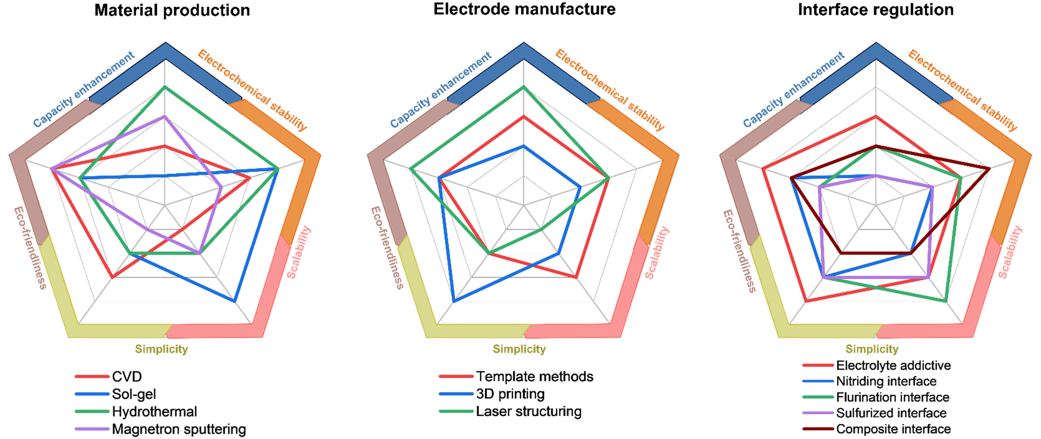
Figure 9. Summary of the multilevel structures of battery electrodes and the classification of structuring strategies accordingly. The structuring strategies are also compared with characteristics in capacity enhancement, electrochemical stability, scalability, simplicity and eco-friendliness. CVD: Chemical vapor deposition.
DECLARATIONS
Authors’ contributions
Made substantial contributions to conception and design of the study and performed data analysis and interpretation: Wen, T.; Rao, R.; Zeng, Y.; Chen, Z.
Performed data acquisition and provided administrative, technical, and material support: Wen, T.; Chen, L.; Huang, R.; Chen, Z.
Availability of data and materials
Not applicable.
AI and AI-assisted tools statement
Not applicable.
Financial support and sponsorship
The authors are grateful for financial support from the National Natural Science Foundation of China (U22A20193), the Key Research Program of Hubei Province (2023BAB036, 2024BAB103), and the Key Research and Development Program of Ningxia Hui Autonomous Region (2024BEE02002).
Conflicts of interest
All authors declared that there are no conflicts of interest.
Ethical approval and consent to participate
Not applicable.
Consent for publication
Not applicable.
Copyright
© The Author(s) 2026.
REFERENCES
1. López-manuel, L.; Vázquez, X. H.; Sartal, A. Firm, industry, and country effects on CO2 emissions levels. Bus. Strat. Env. 2023, 32, 3965-76.
2. Liu, J.; Bao, Z.; Cui, Y.; et al. Pathways for practical high-energy long-cycling lithium metal batteries. Nat. Energy. 2019, 4, 180-6.
3. Tian, Y.; Zeng, G.; Rutt, A.; et al. Promises and challenges of next-generation “beyond Li-ion” batteries for electric vehicles and grid decarbonization. Chem. Rev. 2021, 121, 1623-69.
4. Chen, Z.; Cao, Y.; Qian, J.; Ai, X.; Yang, H. Facile synthesis and stable lithium storage performances of Sn- sandwiched nanoparticles as a high capacity anode material for rechargeable Li batteries. J. Mater. Chem. 2010, 20, 7266.
5. Chen, Z.; Zhou, M.; Cao, Y.; Ai, X.; Yang, H.; Liu, J. In situ generation of few-layer graphene coatings on SnO2 -SiC core-shell nanoparticles for high-performance lithium-ion storage. Adv. Energy. Mater. 2012, 2, 95-102.
6. Kasavajjula, U.; Wang, C.; Appleby, A. J. Nano- and bulk-silicon-based insertion anodes for lithium-ion secondary cells. J. Power. Sources. 2007, 163, 1003-39.
7. Pu, X.; Wang, H.; Zhao, D.; et al. Recent progress in rechargeable sodium-ion batteries: toward high-power applications. Small 2019, 15, e1805427.
8. Fang, Y.; Xiao, L.; Chen, Z.; Ai, X.; Cao, Y.; Yang, H. Recent advances in sodium-ion battery materials. Electrochem. Energ. Rev. 2018, 1, 294-323.
9. Zhang, L.; Wang, W.; Lu, S.; Xiang, Y. Carbon anode materials: a detailed comparison between Na-ion and K-ion batteries. Adv. Energy. Mater. 2021, 11, 2003640.
10. Canepa, P.; Sai, G. G.; Hannah, D. C.; et al. Odyssey of multivalent cathode materials: open questions and future challenges. Chem. Rev. 2017, 117, 4287-341.
11. He, Y.; Jing, L.; Ji, Y.; et al. Revisiting the electrode manufacturing: a look into electrode rheology and active material microenvironment. J. Energy. Chem. 2022, 72, 41-55.
12. Ma, C.; Cai, W.; Zhu, Z.; et al. How binder nanofibration affects the active-material microenvironment in battery electrodes? Adv. Funct. Materials. 2025, 35, 2412193.
13. Jing, L.; Ji, Y.; Feng, L.; et al. Faster and better: a polymeric chaperone binder for microenvironment management in thick battery electrodes. Energy. Storage. Mater. 2022, 45, 828-39.
14. He, Y.; Jing, L.; Feng, L.; et al. A smart polymeric Sol-Binder for building healthy active-material microenvironment in high-energy-density electrodes. Adv. Energy. Mater. 2023, 13, 2203272.
15. Liu, X.; Zeng, Y.; Yuan, W.; Zhang, G.; Zheng, H.; Chen, Z. Advances in multi-scale design and fabrication processes for thick electrodes in lithium-ion batteries. Energy. Reviews. 2024, 3, 100066.
16. Liu, W.; Chen, Z.; Zhou, G.; et al. 3D porous sponge-inspired electrode for stretchable lithium-ion batteries. Adv. Mater. 2016, 28, 3578-83.
19. Kumar, R.; Sharma, T. S. K.; Kim, J.; Choi, W. M.; Singh, L.; Lee, Y. Tuning the cathodic-anodic electrochemical transition in lithium iron borate by optimizing synthesis parameters, anionic doping and potential window. Ceram. Int. 2024, 50, 6184-93.
20. Elango, R.; Demortière, A.; De, A. V.; Morcrette, M.; Seznec, V. Thick binder-free electrodes for Li-ion battery fabricated using templating approach and spark plasma sintering reveals high areal capacity. Adv. Energy. Mater. 2018, 8, 1703031.
21. Jiang, Q.; Cao, R.; Luo, J.; Fang, Y.; Chen, Z.; Cao, Y. Design of gradient porosity architecture with through-hole carbon spheres to promoting fast charging and low-temperature workable lithium-ion batteries. Adv. Energy. Mater. 2025, 15, 2403164.
22. Trogadas, P.; Ramani, V.; Strasser, P.; Fuller, T. F.; Coppens, M. O. Hierarchically structured nanomaterials for electrochemical energy conversion. Angew. Chem. Int. Ed. Engl. 2016, 55, 122-48.
23. Yan, P.; Zheng, J.; Liu, J.; et al. Tailoring grain boundary structures and chemistry of Ni-rich layered cathodes for enhanced cycle stability of lithium-ion batteries. Nat. Energy. 2018, 3, 600-5.
24. Nam, G.; Park, J.; Choi, M.; et al. Carbon-coated core-shell Fe-Cu nanoparticles as highly active and durable electrocatalysts for a Zn-Air battery. ACS. Nano. 2015, 9, 6493-501.
25. Wu, Z.; Ji, S.; Liu, T.; et al. Aligned Li+ tunnels in core-shell Li(NixMnyCoz)O2@LiFePO4 enhances its high voltage cycling stability as Li-ion battery cathode. Nano. Lett. 2016, 16, 6357-63.
26. Zhang, F.; Yang, C.; Gao, X.; et al. SnO2@PANI core-shell nanorod arrays on 3D graphite foam: a high-performance integrated electrode for lithium-ion batteries. ACS. Appl. Mater. Interfaces. 2017, 9, 9620-9.
27. Wang, Y.; Ma, Z.; Chen, Y.; et al. Controlled synthesis of core-shell carbon@MoS2 nanotube sponges as high-performance battery electrodes. Adv. Mater. 2016, 28, 10175-81.
28. Feng, Y.; Zhou, Y.; Zhang, T.; et al. Ultrahigh discharge efficiency and excellent energy density in oriented core-shell nanofiber-polyetherimide composites. Energy. Storage. Mater. 2020, 25, 180-92.
29. Bi, Q.; Ma, Q.; Tao, K.; Han, L. Hierarchical core-shell 2D MOF nanosheet hybrid arrays for high-performance hybrid supercapacitors. Dalton. Trans. 2021, 50, 8179-88.
30. Tang, S. Y.; Yang, C. C.; Su, T. Y.; et al. Design of core-shell quantum dots-3D WS2 nanowall hybrid nanostructures with high-performance bifunctional sensing applications. ACS. Nano. 2020, 14, 12668-78.
31. Wang, S.; Ren, Y.; Liu, G.; Xing, Y.; Zhang, S. Peanut-like MnO@C core-shell composites as anode electrodes for high-performance lithium ion batteries. Nanoscale 2014, 6, 3508-12.
32. Chen, X. Q.; Lin, H. B.; Zheng, X. W.; et al. Fabrication of core-shell porous nanocubic Mn2O3 @TiO2 as a high-performance anode for lithium ion batteries. J. Mater. Chem. A. 2015, 3, 18198-206.
33. Wang, X.; Yushin, G. Chemical vapor deposition and atomic layer deposition for advanced lithium ion batteries and supercapacitors. Energy. Environ. Sci. 2015, 8, 1889-904.
34. Chen, X.; Sawut, N.; Chen, K.; et al. Filling carbon: a microstructure-engineered hard carbon for efficient alkali metal ion storage. Energy. Environ. Sci. 2023, 16, 4041-53.
35. Feng, L.; Zhu, Z.; Yan, R.; et al. Mass production of customizable core-shell active materials in seconds by nano-vapor deposition for advancing lithium sulfur battery. Adv. Sci. 2023, 10, e2207584.
36. Tan, W. K.; Muto, H.; Kawamura, G.; Lockman, Z.; Matsuda, A. Nanomaterial fabrication through the modification of Sol-Gel derived coatings. Nanomaterials 2021, 11, 181.
37. Bokov, D.; Turki, J. A.; Chupradit, S.; et al. Nanomaterial by Sol-Gel method: synthesis and application. Adv. Mater. Sci. Eng. 2021, 2021, 5102014.
38. Kim, M. C.; Nam, K. W.; Hu, E.; et al. Sol-gel synthesis of aliovalent vanadium-doped LiNi0.5Mn1.5O4 cathodes with excellent performance at high temperatures. ChemSusChem 2014, 7, 829-34.
39. Huang, S.; Qin, X.; Miao, X.; Xu, X.; Lei, C.; Wei, T. Novel core-dual shell Si@MoO2 @C nanoparticles as improved anode materials for lithium-ion batteries. ChemElectroChem 2021, 8, 675-80.
40. Liu, S.; Xie, K.; Chen, Z.; et al. A 3D nanostructure of graphene interconnected with hollow carbon spheres for high performance lithium-sulfur batteries. J. Mater. Chem. A. 2015, 3, 11395-402.
41. Chen, F.; Han, J.; Kong, D.; et al. 1000 Wh L-1 lithium-ion batteries enabled by crosslink-shrunk tough carbon encapsulated silicon microparticle anodes. Natl. Sci. Rev. 2021, 8, nwab012.
42. Lakienko, G. P.; Bobyleva, Z. V.; Gorshkov, V. S.; et al. Design of the particle size and morphology of hard carbon anode materials for sodium-ion batteries through hydrothermal carbonization. J. Electrochem. Soc. 2024, 171, 060512.
43. Sun, M.; Wu, J.; Lu, P.; Zhang, Z.; Zhang, Y.; Li, D. Sphere-like MoS2 and porous TiO2 composite film on Ti foil as lithium-ion battery anode synthesized by plasma electrolytic oxidation and magnetron sputtering. J. Alloys. Compd. 2022, 892, 162075.
44. Wu, Y.; Wei, Y.; Wang, J.; Jiang, K.; Fan, S. Conformal Fe3O4 sheath on aligned carbon nanotube scaffolds as high-performance anodes for lithium ion batteries. Nano. Lett. 2013, 13, 818-23.
45. Lobe, S.; Dellen, C.; Finsterbusch, M.; et al. Radio frequency magnetron sputtering of Li7La3Zr2O12 thin films for solid-state batteries. J. Power. Sources. 2016, 307, 684-9.
46. Bohne, L.; Pirk, T.; Jaegermann, W. Investigations on the influence of the substrate on the crystal structure of sputtered LiCoO2. J. Solid. State. Electrochem. 2013, 17, 2095-9.
47. Ursaki, V. V.; Lehmann, S.; Zalamai, V. V.; et al. Core-shell structures prepared by atomic layer deposition on GaAs nanowires. Crystals 2022, 12, 1145.
48. Zhu, C.; Fu, Y.; Yu, Y. Designed nanoarchitectures by electrostatic spray deposition for energy storage. Adv. Mater. 2019, 31, e1803408.
49. Wu, Z.; Li, H.; Xu, Z.; et al. Construction of graphitic carbon nitride/rutile-TiO2 core-shell nanocone arrays by pulsed laser deposition and plasma sputtering reaction deposition. Materials. Letters. 2018, 227, 37-9.
50. Nguyen, C.; Gandon, A.; Do, T. Novel route to preparing magnetic Fe3O4 @SiO2 @MoO3 core-dual shell nanoparticles via solid-phase reverse microemulsion for the oxidative cleavage of fatty acids. ACS. Appl. Nano. Mater. 2020, 3, 10571-7.
51. Ma, Y.; Li, L.; Qian, J.; et al. Materials and structure engineering by magnetron sputtering for advanced lithium batteries. Energy. Storage. Mater. 2021, 39, 203-24.
52. Zhang, T.; Ran, F. Design strategies of 3D carbon-based electrodes for charge/ion transport in lithium ion battery and sodium ion battery. Adv. Funct. Materials. 2021, 31, 2010041.
53. Zhang, X.; Ju, Z.; Zhu, Y.; et al. Multiscale understanding and architecture design of high energy/power lithium-ion battery electrodes. Adv. Energy. Mater. 2021, 11, 2000808.
54. Zhu, P.; Slater, P. R.; Kendrick, E. Insights into architecture, design and manufacture of electrodes for lithium-ion batteries. Mater. Des. 2022, 223, 111208.
55. Zhu, P.; Seifert, H. J.; Pfleging, W. The ultrafast laser ablation of Li(Ni0.6Mn0.2Co0.2)O2 electrodes with high mass loading. Applied. Sciences. 2019, 9, 4067.
56. Zhao, R.; Liu, J.; Gu, J. The effects of electrode thickness on the electrochemical and thermal characteristics of lithium ion battery. Applied. Energy. 2015, 139, 220-9.
57. Zheng, H.; Li, J.; Song, X.; Liu, G.; Battaglia, V. S. A comprehensive understanding of electrode thickness effects on the electrochemical performances of Li-ion battery cathodes. Electrochim. Acta. 2012, 71, 258-65.
58. Parikh, D.; Christensen, T.; Li, J. Correlating the influence of porosity, tortuosity, and mass loading on the energy density of LiNi0.6Mn0.2Co0.2O2 cathodes under extreme fast charging (XFC) conditions. J. Power. Sources. 2020, 474, 228601.
59. Zheng, H.; Tan, L.; Liu, G.; Song, X.; Battaglia, V. S. Calendering effects on the physical and electrochemical properties of
60. Lee, S. G.; Jeon, D. H.; Kim, B. M.; Kang, J. H.; Kim, C. Lattice boltzmann simulation for electrolyte transport in porous electrode of lithium ion batteries. J. Electrochem. Soc. 2013, 160, H258-65.
61. Dubeshter, T.; Sinha, P. K.; Sakars, A.; Fly, G. W.; Jorne, J. Measurement of tortuosity and porosity of porous battery electrodes. J. Electrochem. Soc. 2014, 161, A599-605.
62. Kumberg, J.; Müller, M.; Diehm, R.; et al. Drying of lithium-ion battery anodes for use in high-energy cells: influence of electrode thickness on drying time, adhesion, and crack formation. Energy. Tech. 2019, 7, 1900722.
63. Elango, R.; Nadeina, A.; Cadiou, F.; et al. Impact of electrode porosity architecture on electrochemical performances of 1 mm-thick LiFePO4 binder-free Li-ion electrodes fabricated by spark plasma sintering. J. Power. Sources. 2021, 488, 229402.
64. Hwang, I.; Lee, C. W.; Kim, J. C.; Yoon, S. Particle size effect of Ni-rich cathode materials on lithium ion battery performance. Mater. Res. Bull. 2012, 47, 73-8.
65. Sun, Y.; Zhang, J. P.; Wen, C.; Zhang, L. An enhanced approach for biochar preparation using fluidized bed and its application for H2S removal. Chem. Eng. Process. Process. Intensif. 2016, 104, 1-12.
66. Yan, B.; Zhang, W.; Qin, X.; et al. Salt powder assisted synthesis of nanostructured materials and their electrochemical applications in energy storage devices. Chem. Eng. J. 2020, 400, 125895.
67. Jang, B.; Park, M.; Chae, O. B.; et al. Direct synthesis of self-assembled ferrite/carbon hybrid nanosheets for high performance lithium-ion battery anodes. J. Am. Chem. Soc. 2012, 134, 15010-5.
68. Yu, S. H.; Lee, D. J.; Park, M.; et al. Hybrid cellular nanosheets for high-performance lithium-ion battery anodes. J. Am. Chem. Soc. 2015, 137, 11954-61.
69. Zhou, J.; Qin, J.; Guo, L.; et al. Scalable synthesis of high-quality transition metal dichalcogenide nanosheets and their application as sodium-ion battery anodes. J. Mater. Chem. A. 2016, 4, 17370-80.
70. Shen, F.; Luo, W.; Dai, J.; et al. Ultra-thick, low-tortuosity, and mesoporous wood carbon anode for high-performance sodium-ion batteries. Adv. Energy. Mater. 2016, 6, 1600377.
71. Lu, L. L.; Lu, Y. Y.; Xiao, Z. J.; et al. Wood-inspired high-performance ultrathick bulk battery electrodes. Adv. Mater. 2018, 30, e1706745.
72. Zhu, J.; Shan, Y.; Wang, T.; et al. A hyperaccumulation pathway to three-dimensional hierarchical porous nanocomposites for highly robust high-power electrodes. Nat. Commun. 2016, 7, 13432.
73. Qin, K.; Parisi, C.; Fernandes, F. M. Recent advances in ice templating: from biomimetic composites to cell culture scaffolds and tissue engineering. J. Mater. Chem. B. 2021, 9, 889-907.
74. Huang, C.; Dontigny, M.; Zaghib, K.; Grant, P. S. Low-tortuosity and graded lithium ion battery cathodes by ice templating. J. Mater. Chem. A. 2019, 7, 21421-31.
75. Huang, C.; Leung, C. L. A.; Leung, P.; Grant, P. S. A solid-state battery cathode with a polymer composite electrolyte and low tortuosity microstructure by directional freezing and polymerization. Adv. Energy. Mater. 2021, 11, 2002387.
76. Shi, F.; Xing, B.; Zeng, H.; et al. Ice template induced assembly strategy for preparation of 3D porous carbon frameworks from low-cost carbon quantum dots for high-performance lithium-ion batteries. J. Energy. Storage. 2023, 70, 107982.
77. Wang, J.; Xu, Z.; Eloi, J.; Titirici, M.; Eichhorn, S. J. Ice-templated, sustainable carbon aerogels with hierarchically tailored channels for sodium- and potassium-ion batteries. Adv. Funct. Materials. 2022, 32, 2110862.
78. Yang, H.; Feng, Z.; Teng, X.; Guan, L.; Hu, H.; Wu, M. Three-dimensional printing of high-mass loading electrodes for energy storage applications. InfoMat 2021, 3, 631-47.
79. Pang, Y.; Cao, Y.; Chu, Y.; et al. Additive manufacturing of batteries. Adv. Funct. Materials. 2020, 30, 1906244.
80. Farahani, R. D.; Dubé, M.; Therriault, D. Three-dimensional printing of multifunctional nanocomposites: manufacturing techniques and applications. Adv. Mater. 2016, 28, 5794-821.
81. Park, S.; Shi, B.; Shang, Y.; Deng, K.; Fu, K. Structured electrode additive manufacturing for lithium-ion batteries. Nano. Lett. 2022, 22, 9462-9.
82. Yan, J.; Huang, S.; Lim, Y. V.; et al. Direct-ink writing 3D printed energy storage devices: from material selectivity, design and optimization strategies to diverse applications. Materials. Today. 2022, 54, 110-52.
83. Cao, D.; Xing, Y.; Tantratian, K.; et al. 3D printed high-performance lithium metal microbatteries enabled by nanocellulose. Adv. Mater. 2019, 31, e1807313.
84. Hu, X.; Chen, Y.; Xu, W.; et al. 3D-printed thermoplastic polyurethane electrodes for customizable, flexible lithium-ion batteries with an ultra-long lifetime. Small 2023, 19, e2301604.
85. Maurel, A.; Courty, M.; Fleutot, B.; et al. Highly loaded graphite-polylactic acid composite-based filaments for lithium-ion battery three-dimensional printing. Chem. Mater. 2018, 30, 7484-93.
86. Brown, E.; Yan, P.; Tekik, H.; et al. 3D printing of hybrid MoS2-graphene aerogels as highly porous electrode materials for sodium ion battery anodes. Mater. Des. 2019, 170, 107689.
87. Kushwaha, A.; Jangid, M. K.; Bhatt, B. B.; Mukhopadhyay, A.; Gupta, D. Inkjet-printed environmentally friendly graphene film for application as a high-performance anode in Li-ion batteries. ACS. Appl. Energy. Mater. 2021, 4, 7911-21.
88. Habedank, J. B.; Kraft, L.; Rheinfeld, A.; Krezdorn, C.; Jossen, A.; Zaeh, M. F. Increasing the discharge rate capability of lithium-ion cells with laser-structured graphite anodes: modeling and simulation. J. Electrochem. Soc. 2018, 165, A1563-73.
89. Pfleging, W.; Pröll, J. A new approach for rapid electrolyte wetting in tape cast electrodes for lithium-ion batteries. J. Mater. Chem. A. 2014, 2, 14918-26.
90. Park, J.; Jeon, C.; Kim, W.; Bong, S.; Jeong, S.; Kim, H. Challenges, laser processing and electrochemical characteristics on application of ultra-thick electrode for high-energy lithium-ion battery. J. Power. Sources. 2021, 482, 228948.
91. Li, Y.; Li, Y.; Pei, A.; et al. Atomic structure of sensitive battery materials and interfaces revealed by cryo-electron microscopy. Science 2017, 358, 506-10.
92. Xiang, H.; Shi, P.; Bhattacharya, P.; et al. Enhanced charging capability of lithium metal batteries based on lithium bis(trifluoromethanesulfonyl)imide-lithium bis(oxalato)borate dual-salt electrolytes. J. Power. Sources. 2016, 318, 170-7.
93. Pu, X.; Zhang, S.; Zhao, D.; Xu, Z.; Chen, Z.; Cao, Y. Building the robust fluorinated electrode-electrolyte interface in rechargeable batteries: from fundamentals to applications. Electrochem. Energy. Rev. 2024, 7, 226.
94. Pan, Z.; Chen, H.; Zeng, Y.; Ding, Y.; Pu, X.; Chen, Z. Fluorine chemistry in lithium-ion and sodium-ion batteries. Energy. Mater. 2023, 3, 300051.
95. Ge, J.; Fan, L.; Rao, A. M.; Zhou, J.; Lu, B. Surface-substituted Prussian blue analogue cathode for sustainable potassium-ion batteries. Nat. Sustain. 2022, 5, 225-34.
96. Xu, R.; Cheng, X.; Yan, C.; et al. Artificial interphases for highly stable lithium metal anode. Matter 2019, 1, 317-44.
97. Yan, C.; Xu, R.; Xiao, Y.; et al. Toward critical electrode/electrolyte interfaces in rechargeable batteries. Adv. Funct. Materials. 2020, 30, 1909887.
98. Zhang, S. S. A review on electrolyte additives for lithium-ion batteries. J. Power. Sources. 2006, 162, 1379-94.
99. Zhao, H.; Yu, X.; Li, J.; et al. Film-forming electrolyte additives for rechargeable lithium-ion batteries: progress and outlook. J. Mater. Chem. A. 2019, 7, 8700-22.
100. Zhang, X.; Cheng, X.; Chen, X.; Yan, C.; Zhang, Q. Fluoroethylene carbonate additives to render uniform Li deposits in lithium metal batteries. Adv. Funct. Materials. 2017, 27, 1605989.
101. Eom, K.; Jung, J.; Lee, J. T.; et al. Improved stability of nano-Sn electrode with high-quality nano-SEI formation for lithium ion battery. Nano. Energy. 2015, 12, 314-21.
102. Hu, Z.; Zhao, L.; Jiang, T.; et al. Trifluoropropylene carbonate-driven interface regulation enabling greatly enhanced lithium storage durability of silicon-based anodes. Adv. Funct. Materials. 2019, 29, 1906548.
103. Jurng, S.; Brown, Z. L.; Kim, J.; Lucht, B. L. Effect of electrolyte on the nanostructure of the solid electrolyte interphase (SEI) and performance of lithium metal anodes. Energy. Environ. Sci. 2018, 11, 2600-8.
104. Wu, Z.; Li, S.; Zheng, Y.; et al. The roles of sulfur-containing additives and their working mechanism on the temperature-dependent performances of Li-ion batteries. J. Electrochem. Soc. 2018, 165, A2792-800.
105. Liu, Y.; Lin, D.; Li, Y.; et al. Solubility-mediated sustained release enabling nitrate additive in carbonate electrolytes for stable lithium metal anode. Nat. Commun. 2018, 9, 3656.
106. Weber, R.; Genovese, M.; Louli, A. J.; et al. Long cycle life and dendrite-free lithium morphology in anode-free lithium pouch cells enabled by a dual-salt liquid electrolyte. Nat. Energy. 2019, 4, 683-9.
107. Yang, J.; Fonseca, R. M. T.; Son, S. B.; et al. Dual-salt electrolytes to effectively reduce impedance rise of high-nickel lithium-ion batteries. ACS. Appl. Mater. Interfaces. 2021, 13, 40502-12.
108. Chen, X. R.; Yao, Y. X.; Yan, C.; Zhang, R.; Cheng, X. B.; Zhang, Q. A diffusion--reaction competition mechanism to tailor lithium deposition for lithium-metal batteries. Angew. Chem. Int. Ed. Engl. 2020, 59, 7743-7.
109. Li, S.; Liu, Q.; Wang, X.; et al. Constructing a phosphating-nitriding interface for practically used lithium metal anode. ACS. Materials. Lett. 2020, 2, 1-8.
110. Wan, J.; Chen, W.; Liu, G.; et al. Insights into the nitride-regulated processes at the electrolyte/electrode interface in quasi-solid-state lithium metal batteries. J. Energy. Chem. 2022, 67, 780-6.
111. Zhao, J.; Liao, L.; Shi, F.; et al. Surface fluorination of reactive battery anode materials for enhanced stability. J. Am. Chem. Soc. 2017, 139, 11550-8.
112. Yuan, Y.; Wu, F.; Bai, Y.; et al. Regulating Li deposition by constructing LiF-rich host for dendrite-free lithium metal anode. Energy. Storage. Mater. 2019, 16, 411-8.
113. Lang, J.; Long, Y.; Qu, J.; et al. One-pot solution coating of high quality LiF layer to stabilize Li metal anode. Energy. Storage. Mater. 2019, 16, 85-90.
114. Di, L.; Yufang, C.; Weiwei, S.; et al. Cathode electrolyte interface engineering by gradient fluorination for high-performance lithium rich cathode. Adv. Energy. Mater. 2023, 13, 2301765.
115. Li, T.; Zhang, X.; Shi, P.; Zhang, Q. Fluorinated solid-electrolyte interphase in high-voltage lithium metal batteries. Joule 2019, 3, 2647-61.
116. Lu, Y.; Zhao, C.; Yuan, H.; Cheng, X.; Huang, J.; Zhang, Q. Critical current density in solid-state lithium metal batteries: mechanism, influences, and strategies. Adv. Funct. Materials. 2021, 31, 2009925.
117. Yang, F.; Liu, Y.; Liu, T.; et al. Fluorinated strategies among all-solid-state lithium metal batteries from microperspective. Small. Structures. 2023, 4, 2200122.
118. Zhao, C. Z.; Zhao, Q.; Liu, X.; et al. Rechargeable lithium metal batteries with an in-built solid-state polymer electrolyte and a high voltage/loading Ni-Rich layered cathode. Adv. Mater. 2020, 32, e1905629.
119. Kamaya, N.; Homma, K.; Yamakawa, Y.; et al. A lithium superionic conductor. Nat. Mater. 2011, 10, 682-6.
120. Cheng, X.; Yan, C.; Peng, H.; Huang, J.; Yang, S.; Zhang, Q. Sulfurized solid electrolyte interphases with a rapid Li+ diffusion on dendrite-free Li metal anodes. Energy. Storage. Mater. 2018, 10, 199-205.
121. Wang, Z.; Xu, Z.; Jin, X.; et al. Dendrite-free and air-stable lithium metal batteries enabled by electroless plating with aluminum fluoride. J. Mater. Chem. A. 2020, 8, 9218-27.
122. Yan, C.; Cheng, X. B.; Yao, Y. X.; et al. An armored mixed conductor interphase on a dendrite-free lithium-metal anode. Adv. Mater. 2018, 30, e1804461.
Cite This Article

How to Cite
Download Citation
Export Citation File:
Type of Import
Tips on Downloading Citation
Citation Manager File Format
Type of Import
Direct Import: When the Direct Import option is selected (the default state), a dialogue box will give you the option to Save or Open the downloaded citation data. Choosing Open will either launch your citation manager or give you a choice of applications with which to use the metadata. The Save option saves the file locally for later use.
Indirect Import: When the Indirect Import option is selected, the metadata is displayed and may be copied and pasted as needed.
About This Article
Copyright

Data & Comments
Data
0


Comments
Comments must be written in English. Spam, offensive content, impersonation, and private information will not be permitted. If any comment is reported and identified as inappropriate content by OAE staff, the comment will be removed without notice. If you have any queries or need any help, please contact us at [email protected].