


fig1
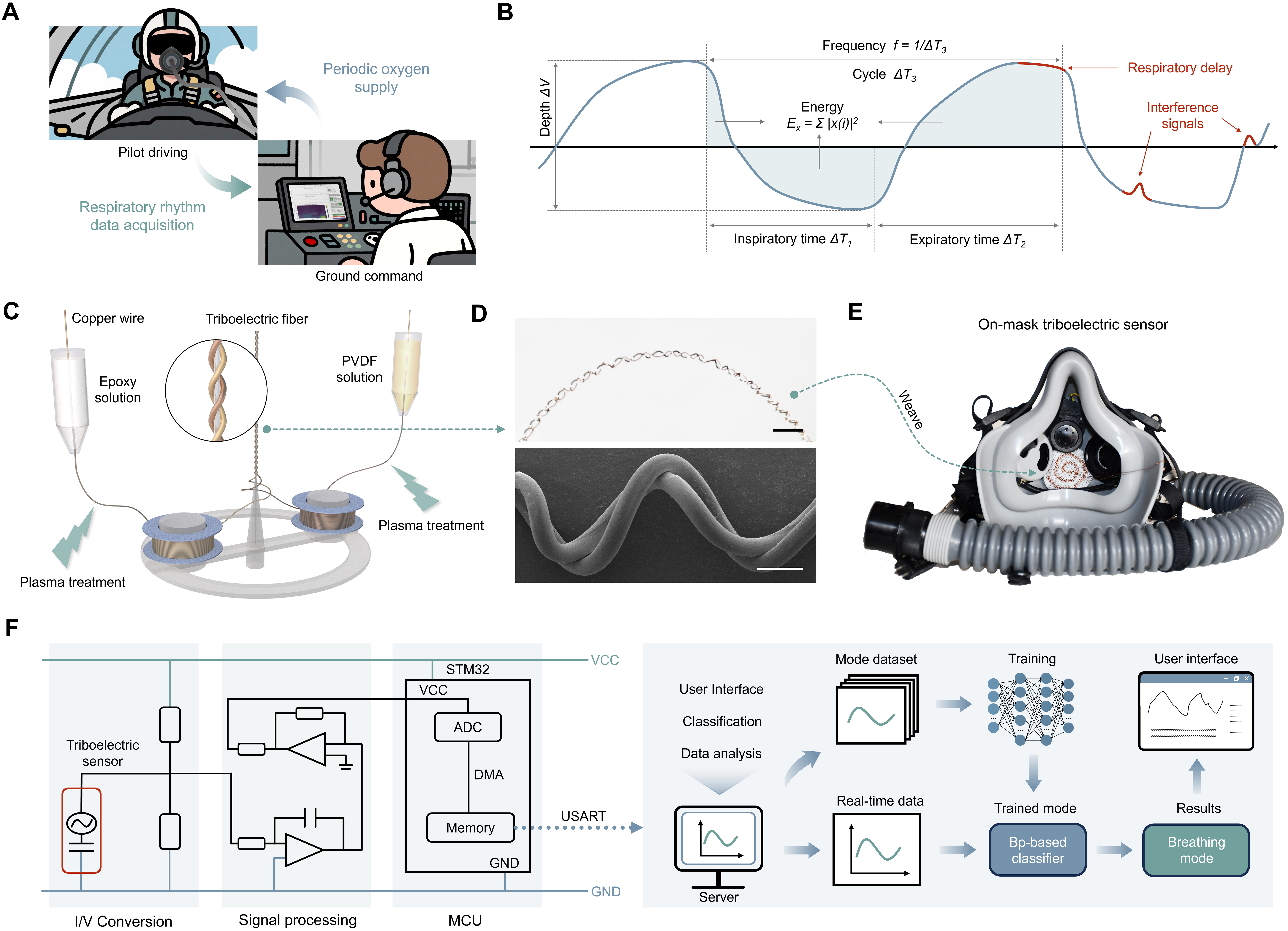
Figure 1. Design and preparation of respiratory monitoring system. (A) Schematic diagram of respiratory monitoring and oxygen supply between pilots and ground control platform; (B) Schematic diagram of periodic respiration waveform with feature extraction and artifact identification, including time, depth, energy, and frequency; (C) Fabrication process of triboelectric fibers; (D) (ⅰ) Digital image (Scale bar: 2 mm) and (ⅱ) SEM image (Scale bar: 2 μm) of triboelectric fibers; (E) Pilot mask integrated with triboelectric sensors; (F) Schematic illustration of the machine learning-assisted respiratory monitoring system. SEM: Scanning electron microscope; PVDF: polyvinylidene fluoride; VCC: voltage common collector; STM32: STMicroelectronics Microcontroller 32-bit; ADC: analog-to-digital converter; DMA: direct memory access; USART: universal synchronous asynchronous receiver transmitter; GND: ground; MCU: microcontroller unit.


