


fig8
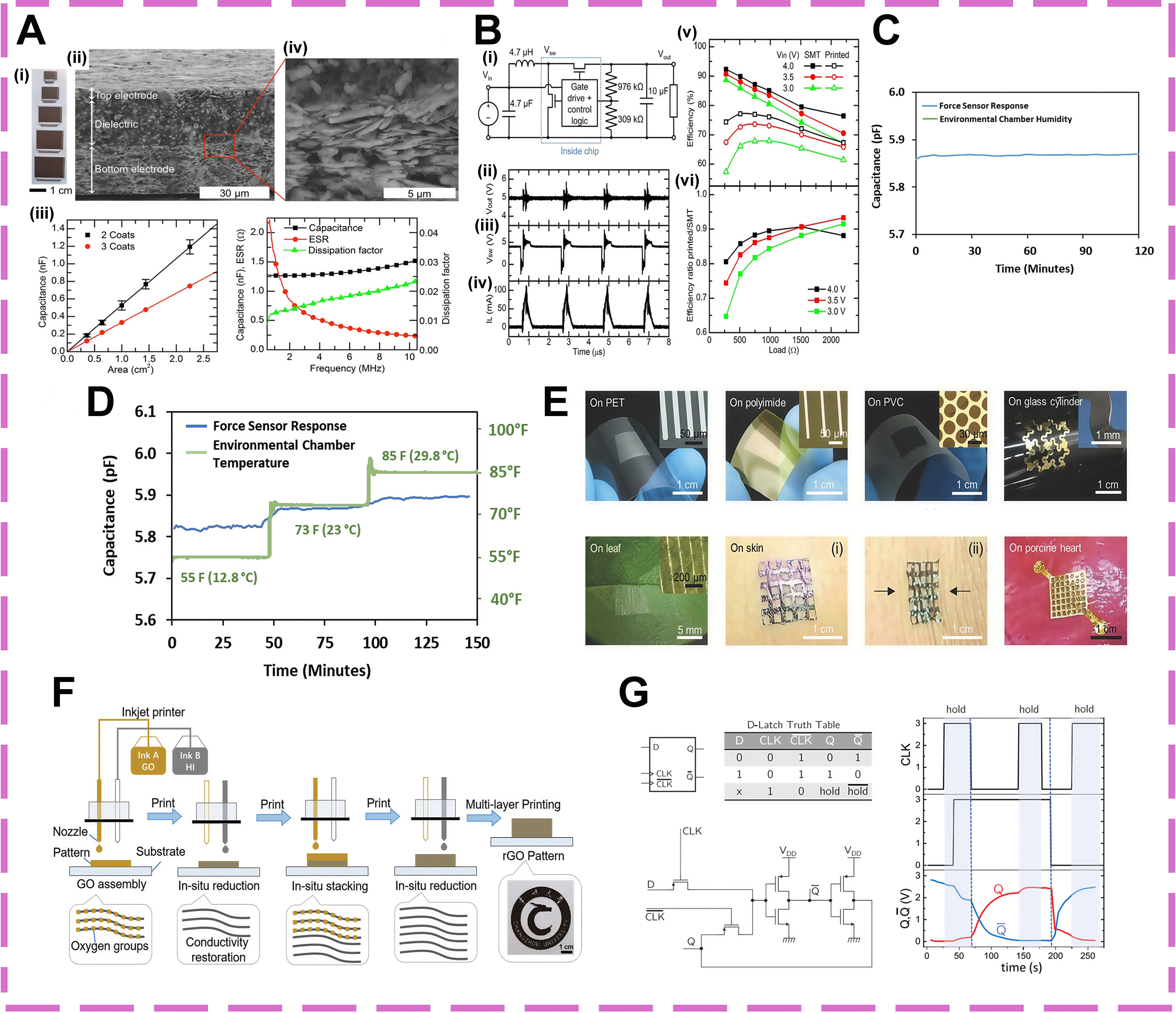
Figure 8. Printing techniques for fabrication, environmental stability, and functional integration of flexible electronic circuits. (A) (i) Photographs of the capacitors with five different areas. (ii) Cross-sectional SEM micrographs of a capacitor with two coats of dielectric, showing the barium titanate dielectric and silver electrodes. (iii) Capacitance of capacitors with 2 and 3 coats of barium titanate dielectric and varying area, measured at 1 MHz. (iv) Capacitance, ESR, and dissipation factor of a 2.25 cm2 capacitor with 2 coats of dielectric, vs. frequency[107]; (B) (i) Diagram of voltage regulator circuit. (ii-iv) Waveforms of (ii) Vout, (iii) Vsw and (iv) current into the inductor, with 4.0 V input voltage and 1 kΩ load resistance, measured using printed inductor. Surface mount resistors and capacitors were used for this measurement. (v) Efficiency of a voltage regulator circuit using all surface-mount components vs. one with printed inductor and resistors, for various load resistances and input voltages. (vi) Ratio of efficiencies of the surface-mount and printed circuits shown in (v)[107]; (C) Effect of relative humidity varying from 20% RH to 80% RH on the force sensor[108]; (D) Effect of temperature on the force sensor[108]; (E) Different thin film devices transfer-printed onto the surfaces of various substrates[109]; (F) A schematic illustration of the in situ approach combining patterning and in situ reduction of GO patterns using reactive inkjet printing[110]; (G) Flexible hybrid complementary-PTL D-Latch on paper[111]. SEM: Scanning electron microscopy; ESR: equivalent series resistance; RH: relative humidity; GO: graphene oxide; PTL: pass transistor logic; SMT: satisfiability modulo theory; PET: polyethylene terephthalate; PVC: polyvinyl chloride; rGO: reduced graphene oxide.


