

Cellulase-mediated surface engineering of cellulose fibers for high-performance cellulose fibers/polyaniline composites flexible electrodes
 0
Graphical Abstract
Abstract
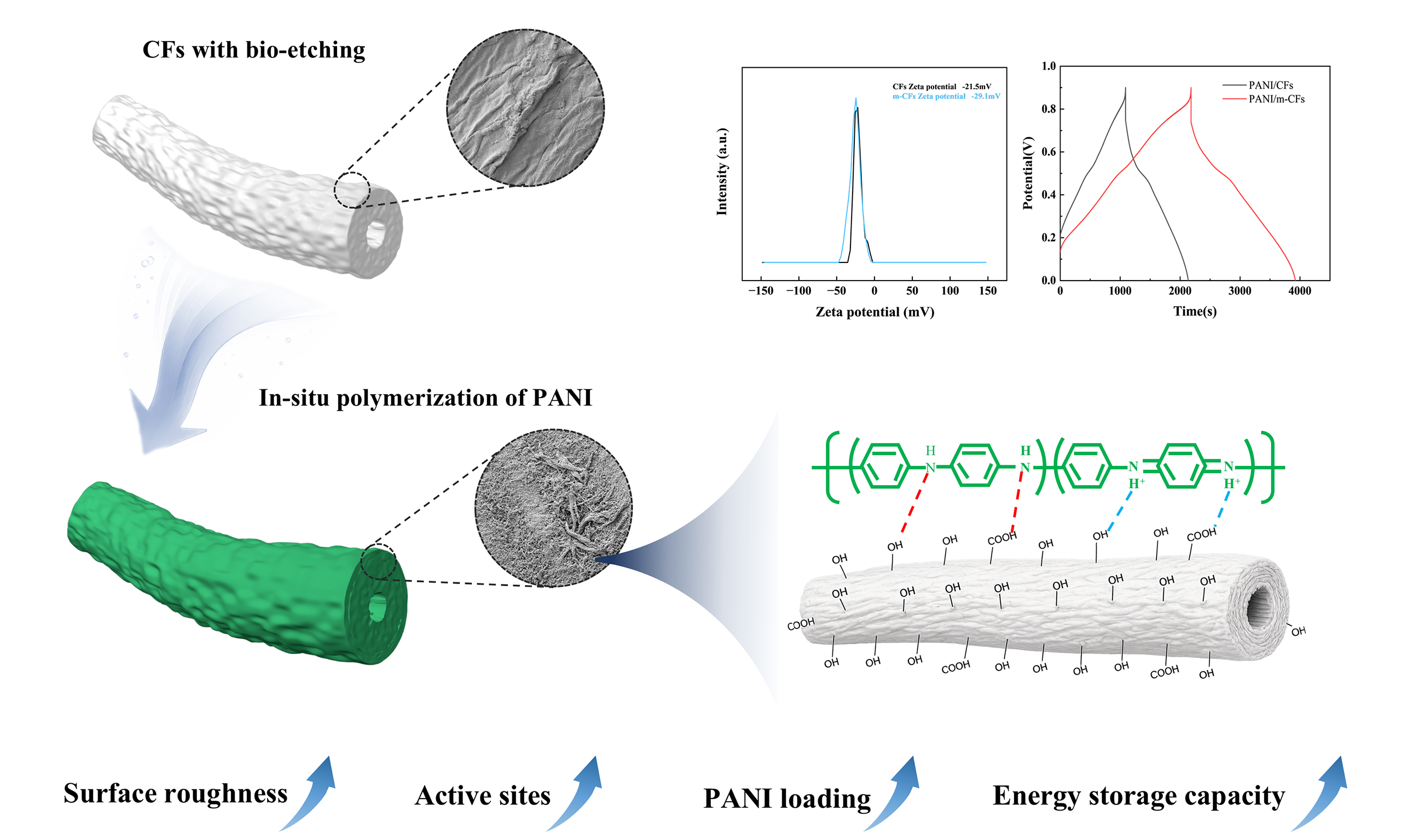
Cellulose-based flexible supercapacitor electrodes, exemplified by cellulose fibers/polyaniline (CFs/PANI) composite electrodes, have emerged as promising candidates for sustainable energy storage. However, their practical application is severely impeded by inherent interfacial incompatibility between CFs and PANI, which restricts PANI mass loading and compromises electrochemical performance. Herein, we propose a novel bio-etching strategy as a targeted pretreatment concept for cellulose surface engineering. The bio-etching process selectively modulates the surface morphology and chemical functionality of CFs, especially increasing the surface roughness and titratable carboxyl group content of CFs while preserving the continuous fiber framework at the optimized treatment time. These changes are consistent with improved PANI deposition during in situ polymerization, potentially aided by electrostatic and hydrogen bonding interactions. The optimized bio-etching (10 min) yields a high PANI:sulfosalicylic acid (SSA) active-phase loading of 2.93 mg/cm2. Benefiting from the bio-etched fiber architecture and increased active-phase loading, the as-fabricated paper-based electrode delivers an areal capacitance of 2,098 mF/cm2 at 1 mA/cm2. In addition, the assembled symmetric supercapacitor exhibits an areal energy density of 111.6 μWh/cm2 at 1 mA/cm2. This work identifies controlled bio-etching as a promising surface engineering strategy for cellulose-based flexible energy-storage electrodes.
Keywords


 Download PDF
INTRODUCTION
Cellulose-based paper materials have attracted considerable attention as promising platforms for flexible energy storage devices due to their low weight, excellent mechanical robustness, and cost-effectiveness[1,2]. However, the intrinsically insulating nature and poor electrochemical activity of cellulose limit its direct application in energy storage systems[3], thereby necessitating integration with electroactive materials to fabricate high-performance electrodes[4]. Among various electroactive materials, polyaniline (PANI) has been investigated because of its facile synthesis, tunable electrical conductivity, and high theoretical specific capacitance[5]. The cellulose network supplies mechanical support, and PANI supplies the main electrochemical response when PANI is combined with cellulose fibers (CFs)[6]. However, achieving a continuous PANI distribution and an effective conductive network remains challenging in fibrous PANI composites[7]. In cellulose/PANI systems, interfacial compatibility between cellulose and PANI is particularly important for achieving uniform polymer deposition[8]. Differences in the surface chemistry of cellulose and aniline can hinder uniform PANI deposition.
To address the interfacial issue, various strategies have been developed. As previously reported, the cellulose fibers modified with zirconium oxyhydroxide can provide coordination sites for phytic acid-doped PANI, enabling a high PANI mass loading[9]. Polymer-cellulose interfacial engineering has also been used to construct hydrogel-enhanced separators for zinc-ion batteries[10,11]. Recent work on flexible energy-storage systems also highlights the roles of material and device architecture[12,13]. Such approaches illustrate the importance of interface design, although additional modification steps can increase processing complexity. Recent studies have shown that enzymatic treatment can alter the accessibility of cellulose[14,15]. Enzymatic processing also provides a mild and environmentally benign route for cellulose modification[16,17]. During a controlled enzymatic hydrolysis process, cellulase preferentially acts on the surface of fibers, exposing more active groups. Moreover, the treatment can also create suitable micro- and nano-scale interfaces, providing additional nucleation and anchoring sites for the deposition of electroactive materials.
In this study, we systematically implement cellulase-mediated bio-etching for cellulose surface engineering to improve the interfacial contact between aniline and CFs, thereby boosting PANI loading. Bio-etching increases surface roughness and titratable carboxyl group content and shifts the zeta potential toward more negative values. These changes may favor interactions between protonated aniline species and CFs. Nevertheless, the intensity of bio-etching must be controlled to avoid excessive structural degradation and preserve the integrity of the cellulose matrix. By controlling the bio-etching parameters, PANI/CFs composite electrodes with increased active-phase loading are fabricated. Furthermore, the energy storage performance and underlying enhancement mechanisms are systematically investigated, identifying a promising route for developing paper-based energy storage devices.
EXPERIMENTAL
Materials and reagents
Cellulose fibers (bleached kraft softwood pulp, CFs) were provided by Zhejiang Huafeng Paper Technology Co., Ltd. Commercial cellulase (CTec3, Novozymes, Sweden) with a nominal activity of 700 EGU/g was used in this study. Aniline (ANI) (≥ 99.5%) was purchased from McLean Biochemical Technology Co., Ltd. (Shanghai, China) and distilled at -0.1 MPa with a rotary evaporator for later use. Ammonium persulfate (APS, ≥ 98%), sulfosalicylic acid (SSA, ≥ 95%), citric acid (CA, ≥ 99.5%) and sodium citrate (≥ 99.0%) were purchased from Aladdin (Shanghai) Co., Ltd. All aqueous solutions were prepared with distilled water.
Fabrication of enzymatically modified cellulose fibers
Prior to enzymatic treatment, the bleached kraft softwood pulp was refined using a Paper and Fibre Research Institute (PFI) mill. Briefly, 30.0 g of oven-dry pulp was adjusted to a consistency of 10 wt% and refined for 2,500 revolutions at a beating pressure of 3.33 N/mm at room temperature (25 °C). Commercial CTec3 cellulase with a nominal activity of
Preparation of PANI/modified cellulose fibers composite electrodes
A 0.5 g portion of wet CFs [or modified cellulose fibers (m-CFs)] with a moisture content of 83.64% and an oven-dry cellulose mass of 0.0818 g was added to a three-necked flask, followed by the addition of 50 mL of 0.3 mol/L sulfosalicylic acid and 0.5 mL of aniline; subsequently, 50 mL of 0.1 mol/L ammonium persulfate was added dropwise. In situ polymerization was performed in an ice water bath for 3 h. The mixture was transferred into a mesh bag and rinsed with deionized water for 5 min to remove soluble salts, unreacted species, and loosely bound oligomers. The resulting precipitate was collected via vacuum filtration, then processed into paper-based electrodes by extrusion drying with a flat hot press and dried to constant mass before gravimetric analysis. Composites prepared with and without bio-etching were denoted as PANI/m-CFs and PANI/CFs respectively, and detailed material parameters are provided in Supplementary Table 2.
Characterizations and performance calculations
Calculation of PANI:SSA active-phase loading in paper-based electrode materials
The PANI:SSA areal loading was calculated from the dry mass increase before and after PANI deposition according to:
where LPANI:SSA is the PANI:SSA active-phase areal loading (mg/cm2), M0 is the dry mass of the cellulose fiber before PANI:SSA deposition (g), M1 is the dry mass of the corresponding electrode after PANI:SSA deposition (g), and A is the electrode area (cm2). All samples were dried to constant mass before weighing. This gravimetric estimate includes the deposited PANI:SSA active phase and is not a measurement of undoped PANI alone. The precursor disk area was 12.566 cm2; the active-phase mass within the effective electrochemical area was calculated from the specimen mass and active-phase mass fraction, assuming a uniform composition. Five independently prepared samples were analyzed for each condition, with results reported as mean [Supplementary Table 2].
Calculation of electrical conductivity
Electrical conductivity was calculated as follows:
where k corresponds to conductivity (S/m), and ρ corresponds to resistivity (Ω·m).
Physical and chemical characterizations
Atomic force microscopy (AFM, Bruker Dimension icon) and field emission scanning electron microscopy (SEM, Sigma 300) were used to characterize the surface morphology and roughness of the samples. The content and distribution of elements in the materials were analyzed by Xplore30 energy dispersive X-ray (EDX) spectroscopy. The zeta potential of cellulose was measured using a Zetasizer nano ZS90 potential analyzer. Samples were analyzed with a Thermo Scientific Nicolet iS 20 Fourier transform infrared spectrometer (FTIR), with a spectral scanning range of 400-4,000 cm-1 and a resolution of 4 cm-1. The composition and crystal structure of the materials were analyzed using a Panaco X-Pert3 Powder X-ray diffractometer (Netherlands). Accessible titratable carboxyl groups were quantified by conductometric titration with NaOH after protonation with HCl; the procedure and calculation are provided in the Supplementary Materials. The species, content and valence of elements in the materials were analyzed by Thermo Scientific K-Alpha X-ray photoelectron spectroscopy (XPS). Thermogravimetric analysis (TGA) was performed using Netzsch TG 209 F3 Tarsus instrument (Germany).
Electrochemical measurements
Electrochemical performance was characterized using an AutoLab PGSTAT 204 electrochemical workstation (Wantong, Switzerland). The paper-based electrode was cut into a 1 cm2 square working electrode, fixed with a polytetrafluoroethylene fixture, and immersed in 1 mol/L H2SO4 electrolyte. A platinum plate and an Ag/AgCl electrode were used as the counter and reference electrodes, respectively. Cyclic voltammetry (CV) and galvanostatic charge-discharge (GCD) measurements were conducted from -0.1 to 0.9 V versus Ag/AgCl. Electrochemical impedance spectroscopy (EIS) measurements were performed at open-circuit potential over 105 to 0.1 Hz with a 5 mV sinusoidal perturbation. Impedance spectra were fitted in ZView using a circuit containing series resistance, charge-transfer resistance, a constant phase element, and a Warburg diffusion element. The fitted parameters and fitting quality are provided in the Supplementary Materials.
where Ca is the areal capacitance (mF/cm2), I is the discharge current (mA), Δt is the discharge time (s), ΔV is the working potential window (V), IRdrop is the IR voltage drop, and A is the area of the working electrode (cm2).
where Cm is the mass-specific capacitance (F/g), I is the discharge current (mA), Δt is the discharge time (s), ΔV is the working potential window (V), IRdrop is the IR voltage drop, and M is the dry PANI:SSA active-phase mass in the working electrode (mg), as specified in Supplementary Table 2. With I expressed in mA and M in mg, Equation (4) yields Cm in mF/mg, which is numerically equivalent to F/g.
The areal energy density E (μWh/cm2) and power density P (μW/cm2) of the symmetric two-electrode supercapacitor were calculated using Equations (5) and (6), respectively. The device capacitance was normalized to the area of one electrode (1.00 cm2). The effective discharge voltage excludes the initial IRdrop, and Δt is the discharge time over the same voltage interval.
The relationship between the peak current (i) and scan rate (v) was fitted to obtain the b value and assess the relative importance of diffusion-controlled and surface-controlled contributions at the selected redox peaks.
where i is the CV current (A), v is the sweep rate (V/s), a is a constant, and k1v and k2v1/2 correspond to the surface-controlled and diffusion-controlled current contributions, respectively.
RESULTS AND DISCUSSION
Mechanisms for the preparation of PANI/m-CFs composites
The bio-etching process of cellulose fibers is schematically illustrated in Figure 1A. Controlled bio-etching modifies the fiber interface in two complementary ways. First, it increases surface roughness and accessibility while maintaining the continuous fiber framework, potentially providing a larger interfacial area and additional physical anchoring and nucleation sites for subsequent PANI growth. Second, the shift toward a more negative zeta potential indicates a change in the surface charge state that is favorable for interaction with protonated aniline species. Figure 1B schematically illustrates the possible hydrogen-bonding and electrostatic interactions at the cellulose-PANI interface. This interpretation is supported by the surface-morphology, surface-charge, active-phase-loading, and elemental-distribution results discussed below.
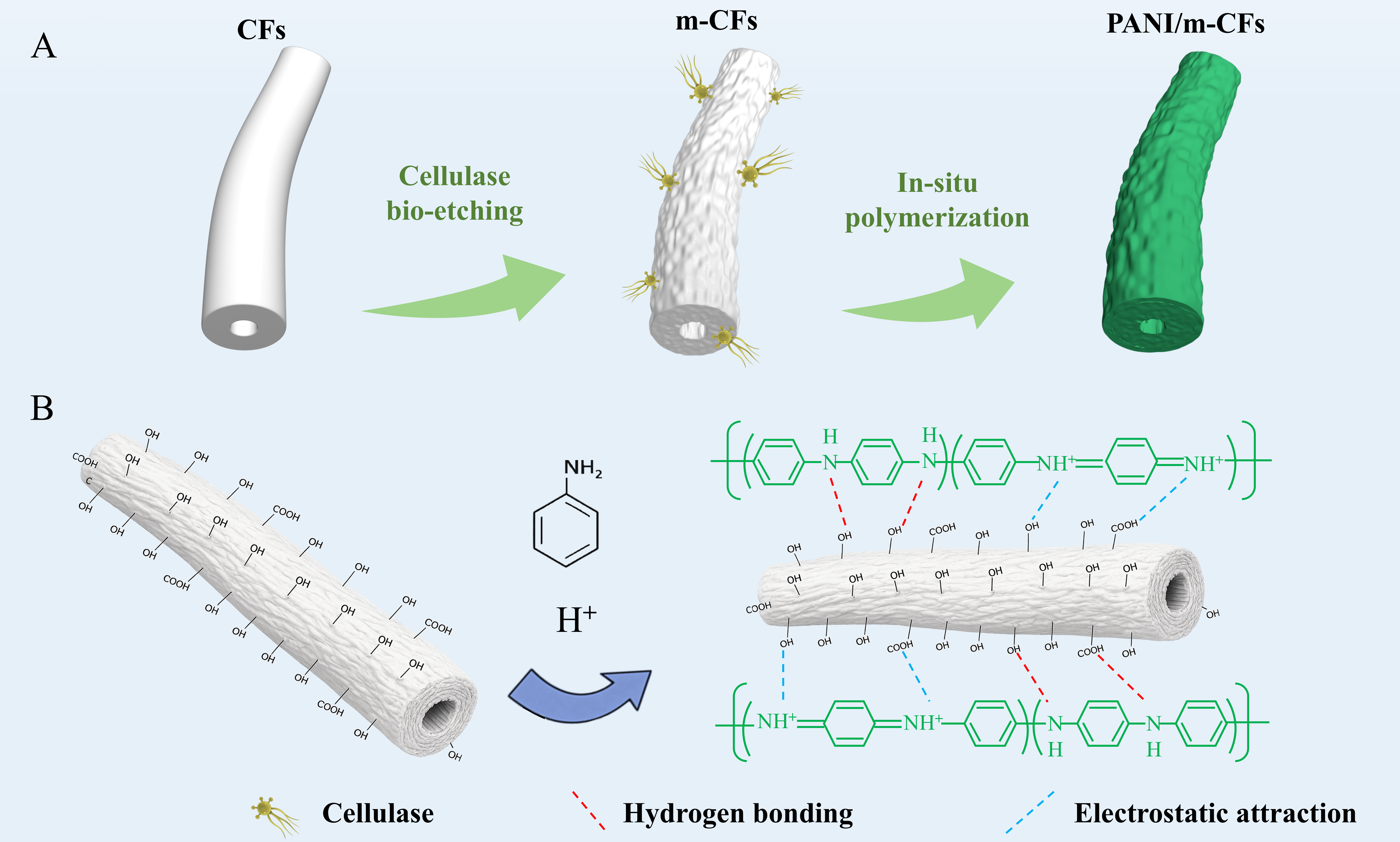
Figure 1. (A) Schematic diagram of bio-etching and in situ polymerization processes; (B) Hydrogen bonding and electrostatic interactions. PANI: Polyaniline; m-CFs: modified cellulose fibers.
Morphological characterizations
The SEM images in Figure 2 show a clear dependence of fiber morphology on bio-etching time. The pristine CFs exhibit a smooth surface [Figure 2A and B]. After 5 min of bio-etching, shallow grooves and fine corrugations appear [Figure 2C and D], indicating that enzymatic attack begins at the outer fiber wall. At
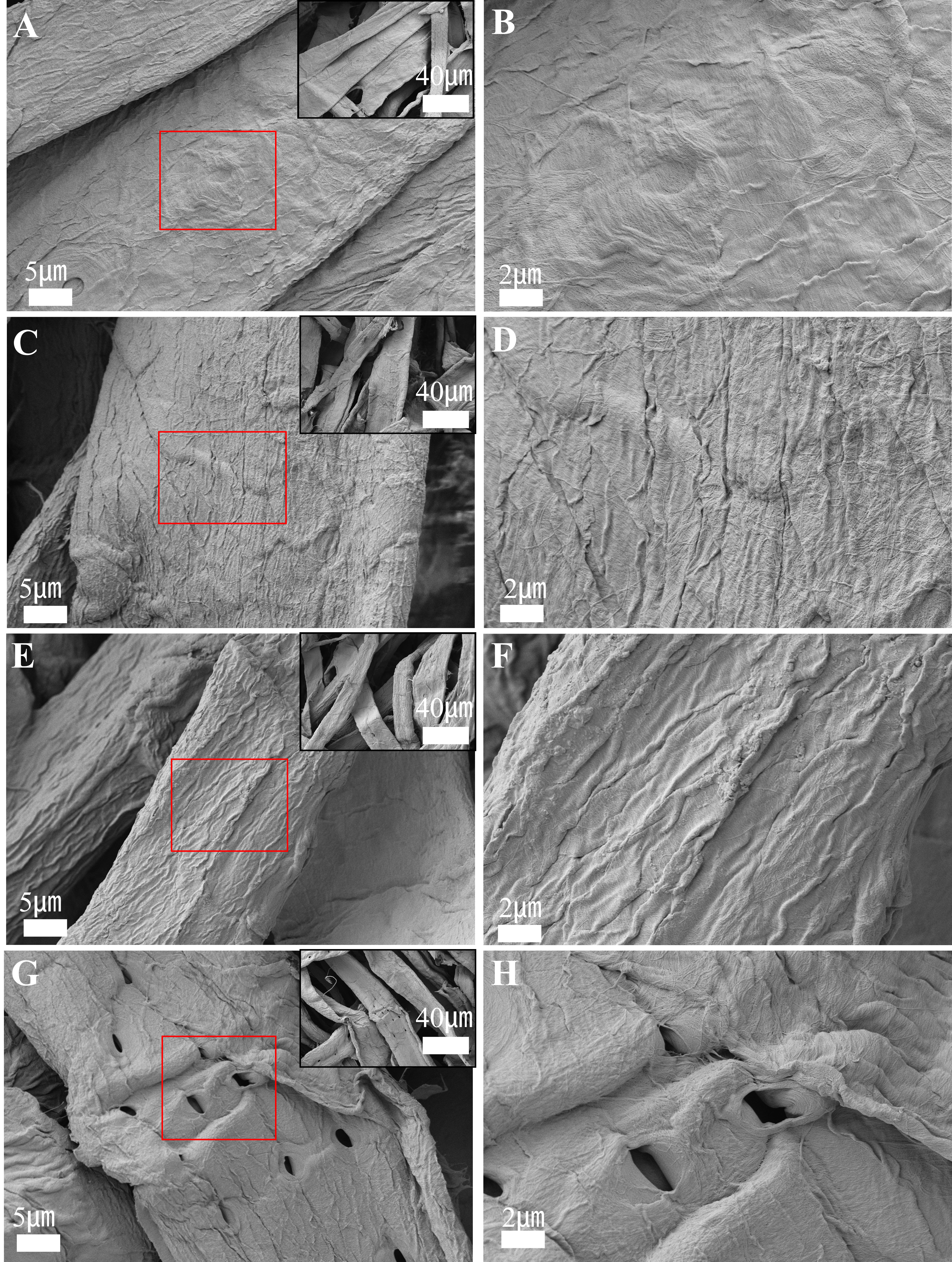
Figure 2. SEM images of CFs subjected to different bio-etching times at low and high magnifications: 0 min (A and B); 5 min (C and D), 10 min (E and F), and 20 min (G and H). SEM: Scanning electron microscopy; CFs: cellulose fibers.
The difference caused by bio-etching becomes more evident after aniline polymerization. On pristine CFs, PANI appears as discontinuous aggregates, indicating limited deposition on the pristine fiber surface [Figure 3A and B]. In contrast, PANI/m-CFs exhibit a dense and uniform coating along the fiber surface [Figure 3C and D]. Energy-dispersive X-ray spectroscopy (EDS) maps of PANI/CFs [Figure 3E-H] and PANI/m-CFs [Figure 3I-L] show the spatial distributions of C, N, O, and S. The more continuous N and S distributions in PANI/m-CFs are consistent with a more uniform coating. These observations further establish the relationship between interfacial modification and PANI deposition. Compared with the relatively smooth pristine CFs, the roughened and more accessible bio-etched fiber surface may provide more available sites for PANI nucleation and growth[18,19]. Accordingly, PANI/m-CFs exhibit a denser and more continuous coating, consistent with similar fibrous cellulose/PANI architectures reported previously[20]. The more homogeneous N and S distributions in the EDS maps are also consistent with increased PANI incorporation.
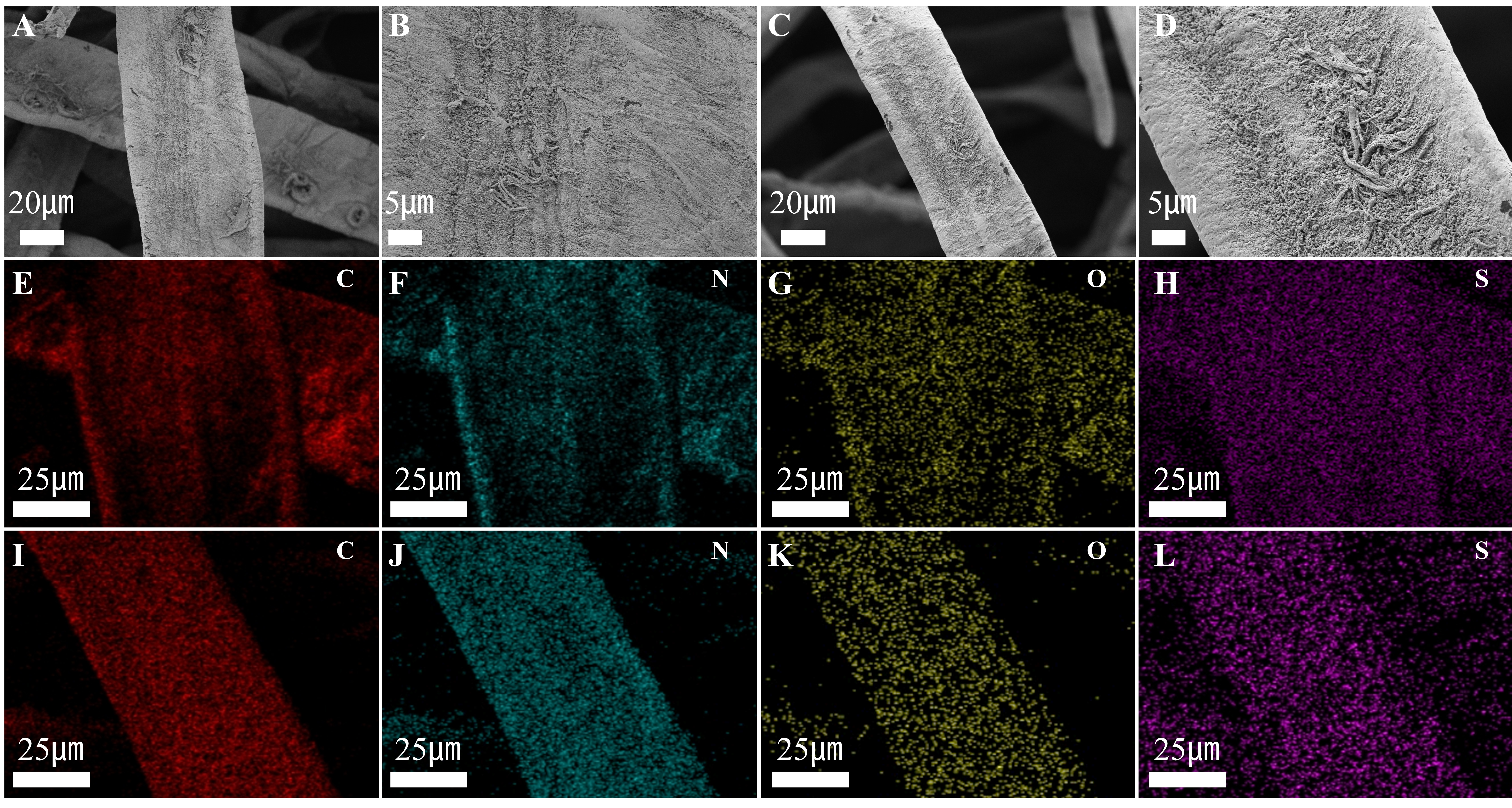
Figure 3. SEM images of PANI/CFs (A and B) and PANI/m-CFs (C and D) composites at different magnifications; EDS elemental mapping of PANI/CFs (E-H) and PANI/m-CFs (I-L). SEM: Scanning electron microscopy; PANI: polyaniline; m-CFs: modified cellulose fibers; EDS: Energy-dispersive X-ray spectroscopy.
Effect of bio-etching conditions on PANI/m-CFs composites
With cellulase dosage and temperature held constant, the effect of bio-etching duration on the properties of CFs was systematically evaluated. As depicted in Figure 4A and Supplementary Table 2, the PANI:SSA active-phase areal loading increases from 1.08 mg/cm2 for untreated fibers to 1.77 and 2.93 mg/cm2 after 5 and 10 min, respectively, before decreasing to 2.04 mg/cm2 after 20 min. This optimal duration also yielded the lowest resistivity of 1.13 Ω·m and a maximum conductivity of 0.88 S/m [Figure 4B]. Prolonging the bio-etching time to 20 min causes a decline in PANI-SSA active-phase loading, consistent with the structural damage observed after excessive bio-etching. Specifically, over-etching triggers localized collapse of the fiber microstructural framework, which may reduce the number of effective anchoring sites [Figure 2G and H]. Moreover, structural damage may impair the mechanical support provided by CFs, impeding the construction of a stable core-shell conductive network.
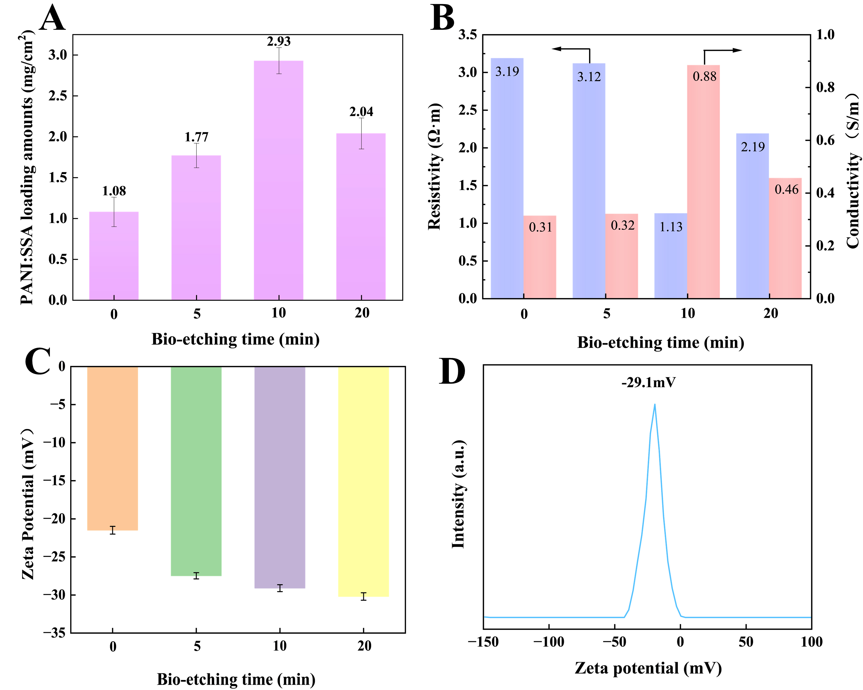
Figure 4. (A) The effect of bio-etching time on PANI:SSA active-phase loading; (B) Conductivity and resistivity of the corresponding samples; (C) Zeta potentials at different bio-etching times; (D) Zeta potential distribution curves for cellulose fibers after 10 min of bio-etching.
The surface charge characteristics, as evaluated by zeta potential measurements, exhibit a pronounced dependence on bio-etching duration. As shown in Figure 4C and D, bio-etching shifts the zeta potential toward more negative values, reaching -29.1 mV after 10 min. The 20 min sample remains strongly negative; therefore, the loading maximum at 10 min cannot be explained by surface charge alone. The corresponding zeta-potential distribution curves of the other samples are provided in Supplementary Figure 2. The enhanced negative surface charge may be associated with bio-etching-induced microfibrillation, which increases the exposed surface area and promotes the exposure of negatively charged functional groups on the fiber surface. Greater surface accessibility may facilitate subsequent PANI:SSA deposition and contribute to the formation of a denser coating [Figure 1B]. To further quantify the variation in accessible carboxyl group content, conductometric titration was performed [Supplementary Table 3]. The titratable carboxyl group content increased from 0.0446 mmol/g for pristine CFs to 0.0563 mmol/g after 10 min of bio-etching, indicating increased accessibility of titratable carboxyl groups.
Structural and compositional analysis
AFM images provide quantitative evidence for the surface changes induced by bio-etching[21]. The three-dimensional topographies [Figure 5A and B] show that bio-etching produces a more uneven surface with greater height variations. The corresponding height maps and cross-sectional profiles are shown in Figure 5C and D for pristine CFs and Figure 5E and F for m-CFs, respectively. The roughness parameters increase from Ra = 57.5 nm and Rq = 77 nm for pristine CFs to Ra = 110 nm and Rq = 140 nm for bio-etched CFs. The cross-sectional profiles taken from representative upper, middle, and lower regions show the same trend: untreated fibers have small height fluctuations, whereas m-CFs display larger peak-to-valley differences. These data indicate that bio-etching reconstructs the fiber surface rather than merely changing its chemical composition. The roughened surface is important for the later polymerization step[22]. The increased roughness may provide additional accessible sites for PANI deposition, consistent with the more continuous coating observed by SEM.
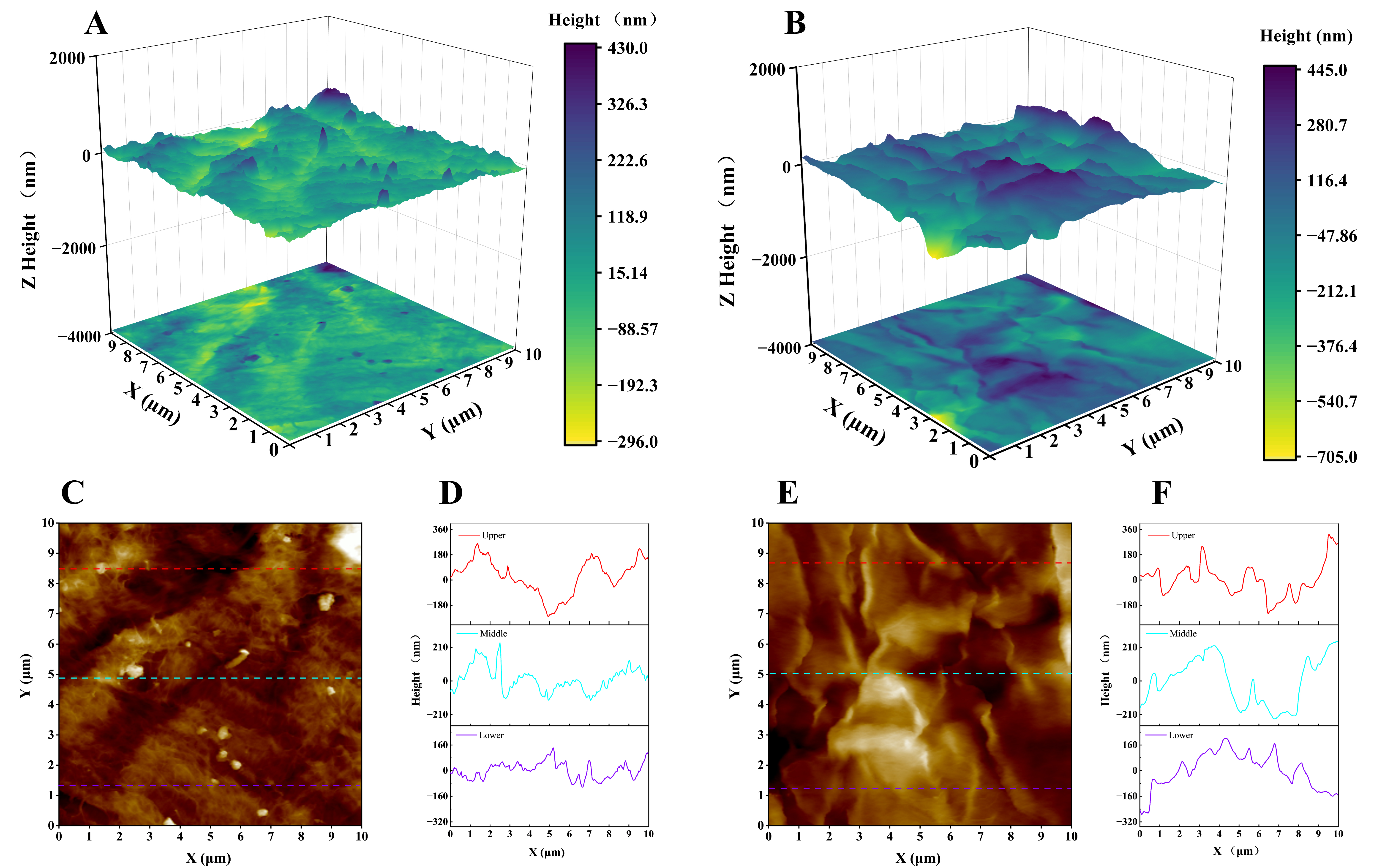
Figure 5. AFM characterization of cellulose fibers before and after bio-etching. (A) 3D surface morphology of CFs; (B) 3D surface morphology of m-CFs; (C) 2D height map of CFs; (D) The corresponding cross-sectional height profile of the original CFs; (E) 2D height map of m-CFs; (F) corresponding cross-sectional height profile of the m-CFs. AFM: Atomic force microscopy; m-CFs: modified cellulose fibers.
FTIR spectra of CFs and m-CFs [Figure 6A] show characteristic cellulose bands at approximately 3,300 and 2,880 cm-1, corresponding to O-H and C-H stretching vibrations, respectively. The characteristic cellulose bands remain present after bio-etching, consistent with retention of the main cellulose functional groups[23]. The bands at 1,106, 1,050, and 1,020 cm-1 are associated with characteristic C-O and C-O-C vibrations of cellulose. Following PANI deposition, characteristic bands appear at 1,569 and 1,487 cm-1, corresponding to the quinoid and benzenoid ring stretching vibrations of PANI, respectively[24]. The band at approximately 1,300 cm-1 is assigned to C-N stretching vibrations of PANI. Relative to PANI/CFs, PANI/m-CFs exhibited stronger PANI-associated absorptions, suggesting increased polymer deposition following bio-etching, in agreement with the TGA and XPS results.
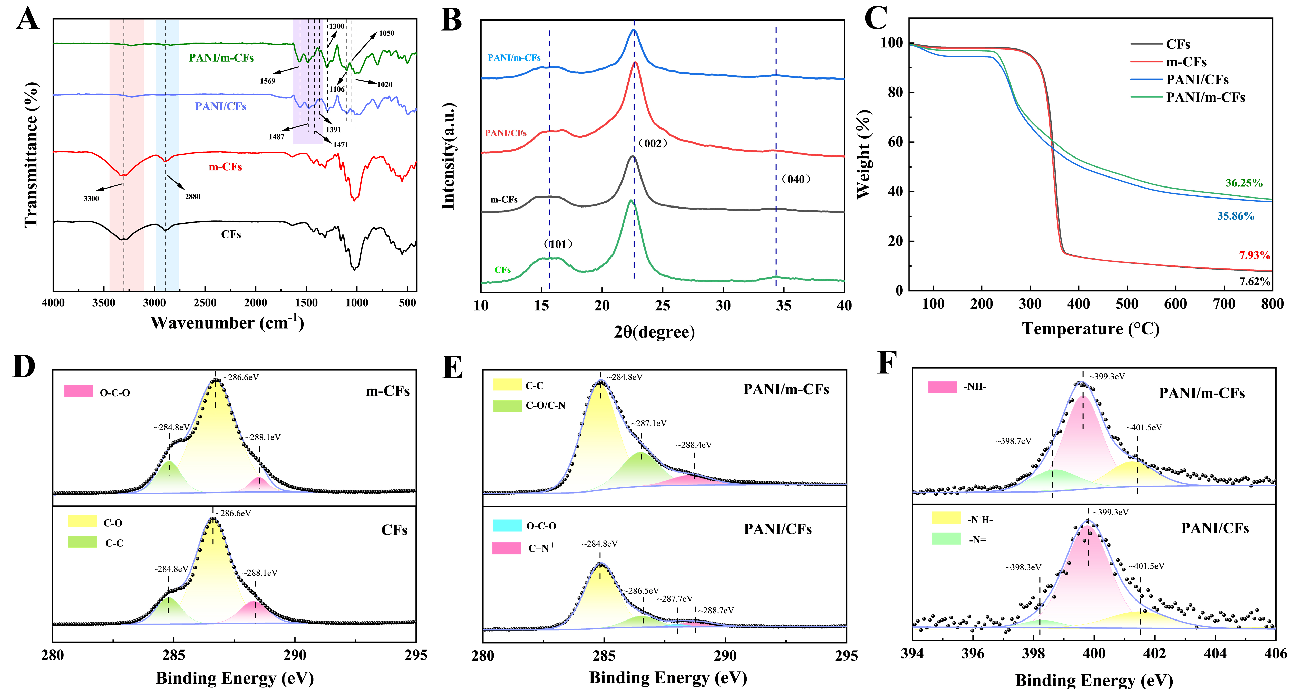
Figure 6. Structural and chemical characterization of the samples. (A) FTIR spectra; (B) XRD patterns; (C) thermogravimetric analysis; (D) high-resolution C 1s spectra of CFs before and after enzymatic etching; high-resolution C 1s (E) and N 1s (F) spectra of PANI/CFs and PANI/m-CFs. PANI: Polyaniline; m-CFs: modified cellulose fibers; FTIR: Fourier transform infrared spectroscopy; XRD: X-ray diffraction.
The X-ray diffraction (XRD) patterns in Figure 6B show that the cellulose I crystalline structure is retained after bio-etching. Pristine CFs exhibit diffraction peaks at 2θ = 16.3° and 22.5°, assigned to the (101) and (002) planes, respectively. After bio-etching, these peaks remain visible with no obvious change in their positions. The crystallinity index calculated using the Segal method was 80.12% for CFs and 80.71% for m-CFs [Supplementary Table 4], consistent with retention of the cellulose I structure. For the PANI-loaded composites, a broad diffraction feature appears at approximately 2θ = 25°, accompanied by a decrease in the intensity of the cellulose reflections, indicating the incorporation of PANI into the cellulose-based composite. The XRD results provide structural information on the coexistence of cellulose and PANI.
TGA was used to compare thermal behavior and composition [Figure 6C]. The mass loss below 100 °C is mainly associated with physically adsorbed water. Bio-etched CFs exhibited a greater mass loss near 230 °C than pristine CFs, implying an increased amount of bound water after treatment. For PANI-containing composites, thermal degradation begins at approximately 250 °C, which is attributed to PANI decomposition and is consistent with the DTG profiles [Supplementary Figure 3]. The pronounced mass loss observed between 280 and 300 °C is related to the degradation of cellulose chains[25]. The residual mass of PANI/m-CFs (36.25%) exceeded that of PANI/CFs (35.86%), indicating a higher PANI incorporation in the bio-etched composite, in agreement with the FTIR and XPS analyses.
XPS analysis confirms the compositional differences induced by bio-etching [Supplementary Figure 4]. The nitrogen content increases from 5.02% for PANI/CFs to 8.10% for PANI/m-CFs. Because nitrogen originates from PANI, the higher N concentration indicates higher polymer incorporation on the bio-etched fibers. The high-resolution C 1s spectra [Figure 6D] show a decrease in the O-C-O signal at 288.0 eV, attributed to bio-etching-mediated cleavage of β-1,4-glycosidic bonds and formation of new chain ends[26].
In the PANI-loaded samples, the peaks at 284.8 eV (C-C), 287.1 eV (C-O/C-N), and 288.4 eV (C=N+) become stronger in PANI/m-CFs [Figure 6E], indicating increased exposure of reactive groups and higher PANI deposition. The N 1s spectra [Figure 6F] show three distinct peaks assigned to quinoid imine
Electrochemical performance and charge storage kinetics
The electrochemical behavior of PANI/CFs and PANI/m-CFs was investigated in a three-electrode cell. The paper-based composites were employed as working electrodes, while a platinum plate and Ag/AgCl electrode served as the counter and reference electrodes, respectively [Figure 7A]. The charge-storage process involves Faradaic reactions of PANI together with ion transport within the porous fiber framework. At 10 mV/s, PANI/m-CFs exhibits a larger CV response with approximately symmetric redox features than PANI/CFs, indicating enhanced pseudocapacitance [Figure 7B][29]. The GCD profiles at 1 mA/cm2 exhibit a longer discharge duration and higher capacitance for PANI/m-CFs [Figure 7C][30]. This behavior is attributed to increased PANI incorporation and a three-dimensional conductive network generated by bio-etching, which promotes electrolyte accessibility and active-material utilization. EIS was employed to investigate interfacial charge-transfer characteristics [Supplementary Table 5 and Figure 7D][31]. The Nyquist plots reveal similar series resistance (Rs) values (2.39 Ω) for both electrodes, whereas PANI/m-CFs display lower charge-transfer resistance (Rct) (1.56 Ω) and Warburg resistance (RW) (1.23 Ω) values than PANI/CFs (2.73 and 3.18 Ω, respectively) [Figure 7E and F]. These results suggest that the porous, fold-rich surface generated by bio-etching facilitates charge transfer and ion transport within the electrode structure[32].
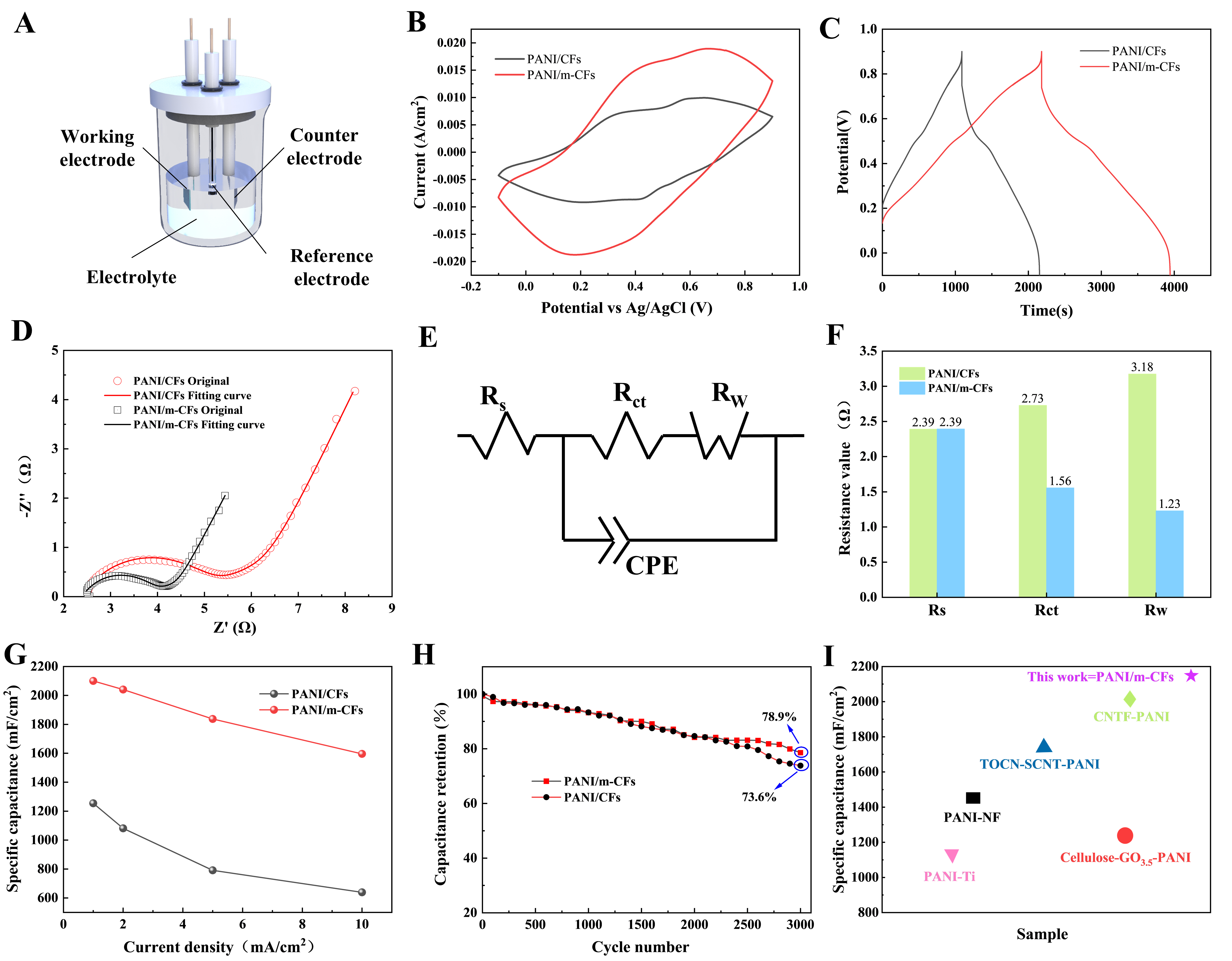
Figure 7. Electrochemical performance evaluation in a three-electrode system: (A) Schematic of the test setup; (B) CV curves at 10 mV/s; (C) GCD profiles at 1 mA/cm2; (D) Nyquist plots for PANI/CFs and PANI/m-CFs; (E) Equivalent circuit model; (F) Fitted resistance values; (G) Areal specific capacitance as a function of current density; (H) Long-term cycling stability; (I) Comparison of areal capacitance with previously reported PANI-based electrodes. PANI: Polyaniline; m-CFs: modified cellulose fibers; CV: cyclic voltammetry; GCD: galvanostatic charge-discharge; CPE: constant phase element; Rct: charge-transfer resistance; RW: Warburg impedance; Rs: series resistance; TOCN: TEMPO-oxidized cellulose nanofibrils; SCNT: sulfonated carbon nanotubes; NF: nickel foam.
At 1 mA/cm2, the areal capacitance increased from 1,254 mF/cm2 for PANI/CFs to 2,098 mF/cm2 for PANI/m-CFs [Figure 7G]. The PANI/m-CFs electrode also retains 78.9% of its initial capacitance after 3,000 cycles, compared with 73.6% for PANI/CFs [Figure 7H]. The improved capacitance retention may be associated with strengthened interfacial interactions between PANI and the bio-etched cellulose fibers, which help maintain the continuity and structural integrity of the conductive network during repeated charge-discharge cycling[29]. As shown in Figure 7I, the PANI/m-CFs electrode exhibits a competitive areal capacitance compared with previously reported PANI-based electrodes[33-37]. Because these values were obtained with different electrolytes, test configurations, and current densities or scan rates, the corresponding testing conditions are summarized in Supplementary Table 6 for reference.
The electrochemical response of PANI/m-CFs can be understood from the combined roles of the PANI coating and the bio-etched fiber network. The PANI layer contributes redox-active sites and electron-conduction paths, while the roughened cellulose network provides electrolyte-accessible channels
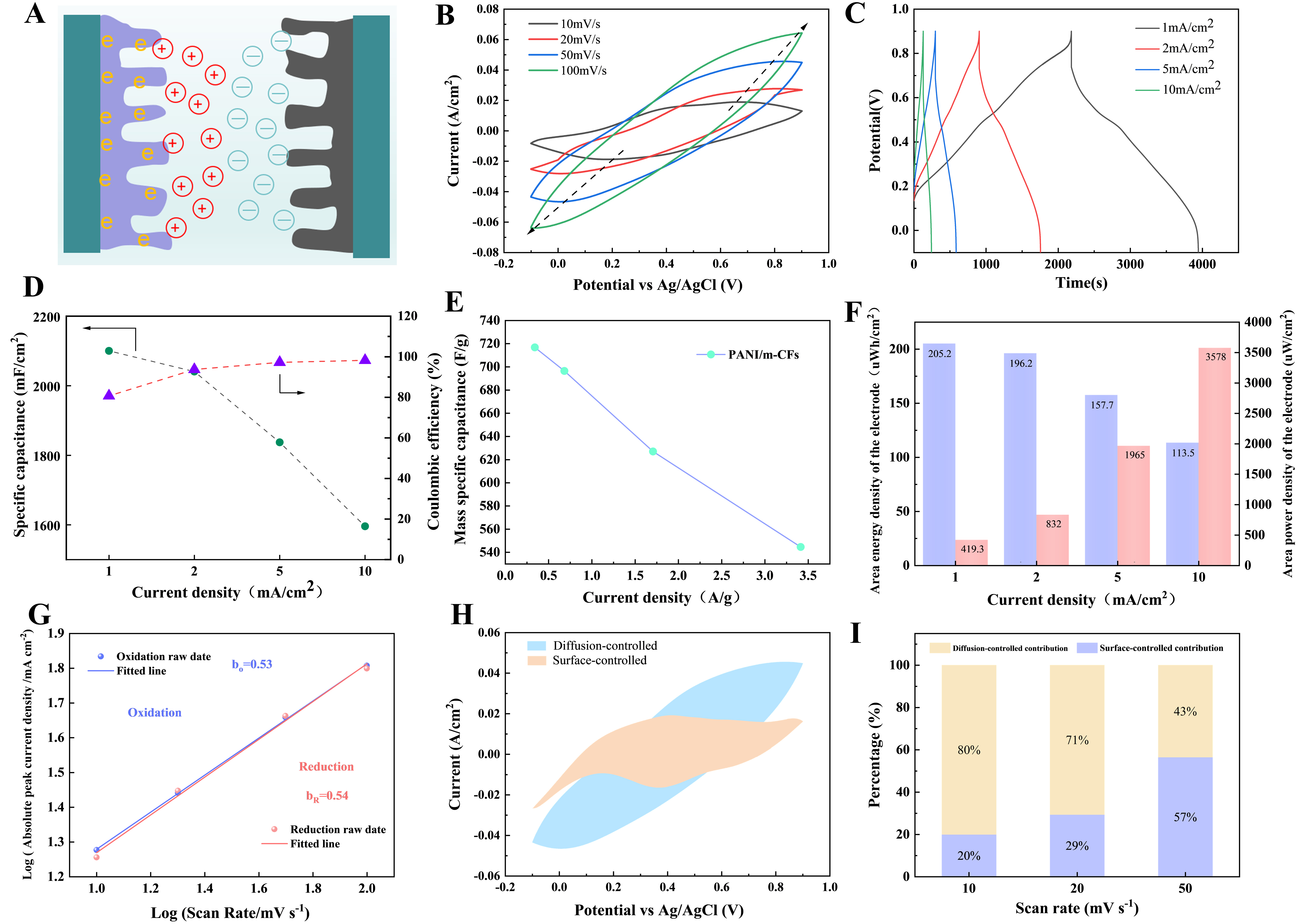
Figure 8. (A) Schematic illustration of the electrochemical process; (B) CV curves of PANI/m-CFs at different scan rates; (C) GCD profiles of PANI/m-CFs at different current densities; (D) Areal specific capacitance and coulombic efficiency of PANI/m-CFs; (E) Mass specific capacitance of PANI/m-CFs; (F) Corresponding areal energy density and areal power density derived from three-electrode measurements; (G) Linear fitting of the absolute peak current density versus scan rate for determining the b-values; (H) Potential-resolved Dunn analysis at a scan rate of 50 mV/s, showing the diffusion-controlled and capacitive current contributions; (I) Relative surface-controlled and diffusion-associated fractions at scan rates of 10-50 mV/s. PANI: Polyaniline; m-CFs: modified cellulose fibers; GCD: galvanostatic charge-discharge; CV: cyclic voltammetry.
The kinetic behavior was further analyzed using the relationship between peak current and scan rate[42]. As shown in Figure 8G, the fitted b values for the oxidation and reduction peaks were 0.53 and 0.54, respectively. The values close to 0.5 indicate that the selected redox peak currents have a predominantly diffusion-dependent scan-rate response. To quantify the contributions, the current response was separated into k1v and k2v1/2 terms according to Equations (9) and (10), and i/v1/2 was fitted as a function of v1/2[43]. As shown in Figure 8H, both contributions coexist throughout the potential window at 50 mV/s, consistent with contributions from both diffusion-controlled and surface-controlled processes in PANI:SSA. As shown in Figure 8I, the surface-controlled contribution increases from 20% to 57% as the scan rate increases. This trend can be attributed to the reduced time available for ion diffusion into the bulk electrode as the scan rate increases, causing the charge-storage process to increasingly rely on rapid surface-accessible reactions. These results reveal that the charge storage mechanism involves both diffusion-controlled Faradaic reactions and surface-controlled processes.
Symmetric supercapacitor performance and bending stability
A symmetric supercapacitor was assembled using two identical PANI/m-CFs electrodes, and tested over a voltage window of 0 to 1.0 V in 1 M H2SO4[44]. The CV curves retain similar profiles as the scan rate increases from 10 to 50 mV/s, with a corresponding increase in current response, consistent with charge storage within 0 to 1.0 V [Figure 9A]. The GCD profiles of the symmetric device exhibit stable and reversible charge-discharge behavior at current densities ranging from 1 to 10 mA/cm2 [Figure 9B]. The Nyquist plot and equivalent circuit fit characterize the device impedance [Figure 9C]. The device achieves an areal capacitance of 1,265 mF/cm2 at 1 mA/cm2 and maintains 217 mF/cm2 at 10 mA/cm2 [Figure 9D], corresponding to 17.2% retention as the current density increases tenfold. Based on the GCD measurements, the device delivers a maximum areal energy density of 111.6 μWh/cm2 at a power density of 398.5 μW/cm2. Even at a high power density of 2,716.9 μW/cm2, an energy density of 8.9 μWh/cm2 is retained [Figure 9E], highlighting the potential of the assembled symmetric supercapacitor for practical energy-storage applications.
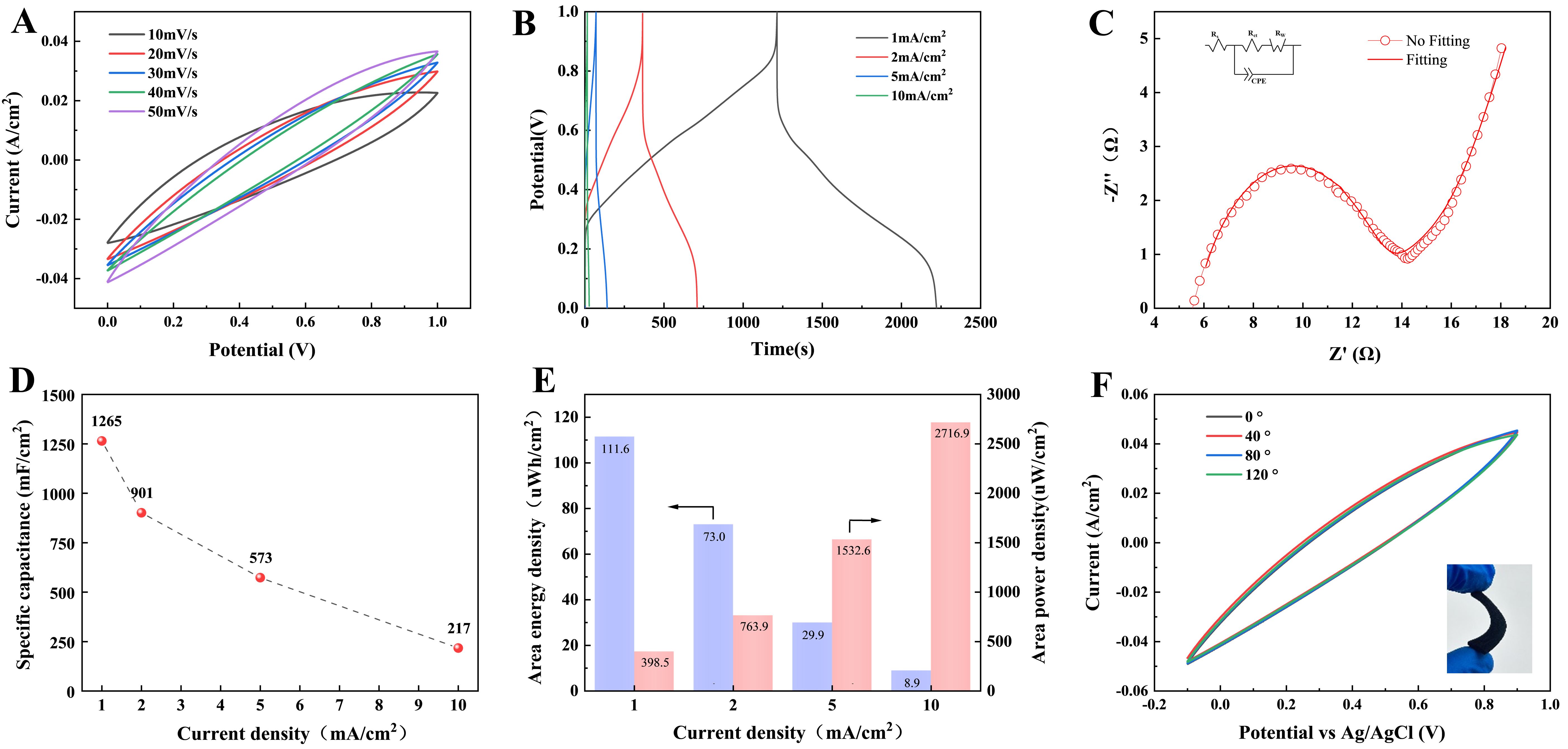
Figure 9. Device-level electrochemical performance of the PANI/m-CFs symmetric supercapacitor and bending stability of the electrode. (A) CV curves at scan rates of 10-50 mV/s; (B) GCD curves at current densities of 1, 2, 5, and 10 mA/cm2; (C) Nyquist plot and fitted curve, with the equivalent circuit used for fitting shown in the inset; (D) Areal capacitance calculated from the GCD curves at different current densities; (E) Corresponding area energy density (blue bars) and area power density (red bars); (F) CV curves of the electrode at bending angles of 0°, 40°, 80°, and 120°; the inset photograph was taken by the authors. PANI: Polyaniline; m-CFs: modified cellulose fibers; CV: cyclic voltammetry; GCD: galvanostatic charge-discharge; CPE: constant phase element; Rs: series resistance; Rct: charge-transfer resistance; RW: Warburg impedance.
Mechanical deformation tolerance was further assessed by static bending[45]. CV curves recorded at 0°, 40°, 80°, and 120° nearly overlap, with only minor differences in current response [Figure 9F]. The GCD profiles at the same bending angles also show comparable charge-discharge times and curve shapes [Supplementary Figure 5]. These results indicate that the electrode maintains a similar electrochemical response at the tested static bending angles, consistent with preservation of conductive pathways within the cellulose-fiber/PANI network. The bending measurements were performed on the electrode and do not establish the mechanical durability of the assembled symmetric device or its resistance to repeated bending.
CONCLUSIONS
This work demonstrates cellulase-mediated bio-etching as a mild pretreatment for tuning cellulose fibers before PANI deposition. Under the optimized bio-etching conditions of a cellulase dosage of 1.75 EGU/g cellulose, 50 °C, and a treatment time of 10 min, the fiber surface is roughened while the main fiber skeleton is retained. The treatment increases surface roughness from 57.5 to 110 nm and shifts the zeta potential to -29.1 mV, consistent with surface modification that may facilitate PANI deposition. As a result, the PANI:SSA active-phase loading reaches 2.93 mg/cm2. The PANI/m-CFs electrode achieves an areal capacitance of 2,098 mF/cm2 at 1 mA/cm2, and retains 78.9% of its initial capacitance after 3,000 cycles. The assembled symmetric supercapacitor device achieves an areal energy density of 111.6 μWh/cm2 at 1 mA/cm2. The electrode maintains a similar electrochemical response under static bending at angles of 0° to 120°. These results indicate that controlled bio-etching is an effective route for preparing high-loading cellulose/PANI paper electrodes for flexible energy-storage applications.
DECLARATIONS
Authors’ contributions
Performed the experiments, acquired and analyzed the data, interpreted the results, and drafted the original manuscript: Zhai, P.
Made substantial contributions to the conception and design of the study, supervised the research, provided resources and administrative support, and contributed to data analysis and interpretation: Chang, Z.; Zhai, S.; Ni, Y.
Contributed to data acquisition and validation and provided technical and material support: Zhao, X.; Wang, H.; Jia, Z.; Huang, L.; Chen, X.; Meng, Y.; Fang, L.; Meng, Y.; Du, L.; Zhao, H.; Guo, D.; Sha, L.
All authors read and approved the final manuscript.
Availability of data and materials
The data supporting the findings of this study are available within this Article and its Supplementary Materials. Further data are available from the corresponding authors upon request.
AI and AI-assisted tools statement
Not applicable.
Financial support and sponsorship
This work was supported by the Fundamental Research Fund of Zhejiang University of Science and Technology (Grant No. 2025QN054) and the National Natural Science Foundation of China (Grant No. 32101465). This work was also supported by the Major R&D Program of Quzhou (Grant No. 2025K164).
Conflicts of interest
Chang, Z.; Meng, Y.; Du, L. are affiliated with Zhejiang Jinchang Special Paper Co., Ltd. Fang, L. is affiliated with Zhejiang Jiaweikang Special Paper Co., Ltd., while the other authors have declared that they have no conflicts of interest.
Ethical approval and consent to participate
Not applicable.
Consent for publication
Not applicable.
Copyright
© The Author(s) 2026.
Supplementary Materials
REFERENCES
1. Xu, T.; Du, H.; Liu, H.; et al. Advanced nanocellulose-based composites for flexible functional energy storage devices. Adv. Mater. 2021, 33, e2101368.
2. Shi, L.; Xiao, T.; Wang, X.; Huang, L.; Wu, L.; Shi, H. Recent advances in sustainable cellulose-based supercapacitors: diverse applications, crucial challenges, and coping strategies. Carbohydr. Polym. 2026, 371, 124478.
3. Wei, J.; Zhang, P.; Sun, J.; et al. Advanced electrolytes for high-performance aqueous zinc-ion batteries. Chem. Soc. Rev. 2024, 53, 10335-69.
4. Habibi, Y.; Lucia, L. A.; Rojas, O. J. Cellulose nanocrystals: chemistry, self-assembly, and applications. Chem. Rev. 2010, 110, 3479-500.
5. Zhang, T.; Chen, S.; Petkov, P. S.; et al. Two-dimensional polyaniline crystal with metallic out-of-plane conductivity. Nature 2025, 638, 411-7.
6. Jian, M.; Lv, Z.; Zhang, R.; et al. Low-temperature assisted in-situ layer-by-layer polymerization of polyaniline/cellulose fibers with high strength and conductivity for sensing multiple signals. Chem. Eng. J. 2025, 514, 163446.
7. Chen, M.; Zhu, J.; Zhang, K.; et al. Carbon nanofiber/polyaniline composite aerogel with excellent electromagnetic interference shielding, low thermal conductivity, and extremely low heat release. NanoMicro. Lett. 2024, 17, 80.
8. Wang, C.; Liao, Y.; Yu, H. Y.; Dong, Y.; Yao, J. Homogeneous wet-spinning construction of skin-core structured PANI/cellulose conductive fibers for gas sensing and e-textile applications. Carbohydr. Polym. 2023, 319, 121175.
9. Chang, Z.; An, X.; Qian, X. High mass loading polyaniline layer anchored cellulose fibers: enhanced interface junction for high conductivity and flame retardancy. Carbohydr. Polym. 2020, 230, 115660.
10. Guo, Z.; Lang, A.; Liang, Z.; et al. Strong polymer-cellulose interfacial engineering enables hydrogel-enhanced separators with multiscale networks for zinc-ion batteries. Int. J. Biol. Macromol. 2025, 322, 146805.
11. Chen, Q.; Liu, Y.; Yang, J.; et al. Cellulose ionogels: recent advancement in material, design, performance and applications. Resour. Chem. Mater. 2025, 4, 100088.
12. Zhang, Y.; Tang, C.; Lu, S.; Zeng, Y.; Hua, Q.; Zhang, Y. MnO2 nanoflower intercalation on Ti3C2Tx MXene with expanded interlayer spacing for flexible asymmetric supercapacitors. Carbon. Neutraliz. 2025, 4, e70006.
13. Zhang, Q.; Gao, X.; Liu, X.; et al. Flexible wearable energy storage devices: materials, structures, and applications. Battery. Energy. 2024, 3, 20230061.
14. Tong, X.; He, Z.; Zheng, L.; Pande, H.; Ni, Y. Enzymatic treatment processes for the production of cellulose nanomaterials: a review. Carbohydr. Polym. 2023, 299, 120199.
15. Yuan, H.; Hao, R.; Sun, H.; et al. Engineered Janus cellulose membrane with the asymmetric-pore structure for the superhigh-water flux desalination. Carbohydr. Polym. 2022, 291, 119601.
16. Li, X.; Xiang, Z.; Dang, W.; et al. High-yield and scalable cellulose nanomesh preparation via dilute acid vapor and enzymatic hydrolysis-mediated nanofabrication. Carbohydr. Polym. 2024, 323, 121370.
17. Shoda, S.; Uyama, H.; Kadokawa, J.; Kimura, S.; Kobayashi, S. Enzymes as green catalysts for precision macromolecular synthesis. Chem. Rev. 2016, 116, 2307-413.
18. Asztalos, A.; Daniels, M.; Sethi, A.; et al. A coarse-grained model for synergistic action of multiple enzymes on cellulose. Biotechnol. Biofuels. 2012, 5, 55.
19. Ma, R.; Zhao, B.; Sun, X.; et al. 3D porous cellulose/polyaniline aerogel composite as a high-performance electrode for selective electrosorption of rhenium. Water. Res. 2026, 292, 125374.
20. Illa, M. P.; Pathak, A. D.; Sharma, C. S.; Khandelwal, M. Bacterial cellulose-polyaniline composite derived hierarchical nitrogen-doped porous carbon nanofibers as anode for high-rate lithium-ion batteries. ACS. Appl. Energy. Mater. 2020, 3, 8676-87.
21. Foster, E. J.; Moon, R. J.; Agarwal, U. P.; et al. Current characterization methods for cellulose nanomaterials. Chem. Soc. Rev. 2018, 47, 2609-79.
22. Wu, J.; Dong, Y.; Zhang, H.; Liu, J.; Renneckar, S.; Saddler, J. Reduced cellulose accessibility slows down enzyme-mediated hydrolysis of cellulose. Bioresour. Technol. 2023, 371, 128647.
23. Hashemzehi, M.; Håkansson, H.; Carlsson Kvarnlöf, G.; Henriksson, G.; Sjöstrand, B. Enzyme-enhanced manufacturing of cationized dialdehyde cellulose. Biomacromolecules 2025, 26, 5581-90.
24. Ragazzini, I.; Gualandi, I.; D’Altri, G.; et al. Polyaniline/poly (2-acrylamido-2-methyl-1-propanesulfonic acid) modified cellulose as promising material for sensors design. Carbohydr. Polym. 2023, 316, 121079.
25. Wan, J.; Hu, R.; Li, J.; et al. A universal construction of robust interface between 2D conductive polymer and cellulose for textile supercapacitor. Carbohydr. Polym. 2022, 284, 119230.
26. Lei, J.; Deng, L.; Chen, Z.; Li, X.; Li, K.; Lee, J. Efficient in situ saccharification of microcrystalline cellulose over immobilized cellulase on magnetic biochar in ionic liquid media. Chem. Eng. J. 2024, 485, 149990.
27. Feng, J.; Jin, R.; Zhou, J.; Tian, T. Green self-assembly of digestate-derived humic acid/sulfonated polyaniline nanocomposites for high-performance flexible supercapacitors. Bioresour. Technol. 2026, 450, 134394.
28. Wang, Y.; Liu, Z.; Li, J.; et al. Polyaniline-on-MOF protects the MOF structure during carbonization for the construction of a portable sensor to detect tert-butylhydroquinone. Nano. Energy. 2025, 135, 110655.
29. Na, Y. W.; Cheon, J. Y.; Kim, J. H.; et al. All-in-one flexible supercapacitor with ultrastable performance under extreme load. Sci. Adv. 2022, 8, eabl8631.
30. Yu, T.; Zhang, P.; Chen, L.; Huang, L.; Wu, H.; Zhou, X. Preparation of high-performance supercapacitors using bark activated carbon/polyaniline composite electrode. Biomass. Bioenergy. 2025, 197, 107813.
31. Zhang, L.; Dai, Y.; Li, C.; et al. Recent advances in electrochemical impedance spectroscopy for solid-state batteries. Energy. Storage. Mater. 2024, 69, 103378.
32. Augustyn, V.; Come, J.; Lowe, M. A.; et al. High-rate electrochemical energy storage through Li+ intercalation pseudocapacitance. Nat. Mater. 2013, 12, 518-22.
33. Zhou, H.; Ren, Z.; Ou, T.; Zhai, H. Template-free water splitting preparation of carbon nanotube foam for high-efficiency charge storage and electromagnetic interference shielding. J. Power. Sources. 2025, 644, 237096.
34. Hu, Y.; Zhan, Y.; Xu, M.; et al. One-step preparation of flexible nanocellulose-based composite hydrogel supercapacitors with high specific capacitance. Compos. Sci. Technol. 2022, 230, 109725.
35. Li, Y.; Xia, Z.; Gong, Q.; et al. Green synthesis of free standing cellulose/graphene oxide/polyaniline aerogel electrode for high-performance flexible all-solid-state supercapacitors. Nanomaterials 2020, 10, 1546.
36. Hossain, M. S.; Kabir, M. H.; Shaikh, M. A. A.; Pabel, M. Y.; Yasmin, S. Development of a high-capacitance flexible supercapacitor with enhanced cycling stability based on nanotubular polyaniline-modified titanium sheet. Mater. Chem. Phys. 2024, 322, 129586.
37. Shah, S. S.; Das, H. T.; Barai, H. R.; Aziz, M. A. Boosting the electrochemical performance of polyaniline by one-step electrochemical deposition on nickel foam for high-performance asymmetric supercapacitor. Polymers 2022, 14, 270.
38. Liang, Y.; Wei, Z.; Wang, H.; Flores, M.; Wang, R.; Zhang, X. Flexible and freestanding PANI:PSS/CNF nanopaper electrodes with enhanced electrochemical performance for supercapacitors. J. Power. Sources. 2022, 548, 232071.
39. Egun, I. L.; Akinwolemiwa, B.; Yin, B.; et al. Conversion of high moisture biomass to hierarchical porous carbon via molten base carbonisation and activation for electrochemical double layer capacitor. Bioresour. Technol. 2024, 409, 131251.
40. Yuan, T.; Zhang, Z.; Liu, Q.; Liu, X. T.; Miao, Y. N.; Yao, C. L. MXene (Ti3C2Tx)/cellulose nanofiber/polyaniline film as a highly conductive and flexible electrode material for supercapacitors. Carbohydr. Polym. 2023, 304, 120519.
41. Say, M. G.; Brett, C. J.; Edberg, J.; et al. Scalable paper supercapacitors for printed wearable electronics. ACS. Appl. Mater. Interfaces. 2022, 14, 55850-63.
42. Tong, X.; Sheng, G.; Yang, D.; et al. Crystalline tetra-aniline with chloride interactions towards a biocompatible supercapacitor. Mater. Horiz. 2022, 9, 383-92.
43. Vadiyar, M. M.; Kim, J.; Bae, J.; Nam, K. Imidazole linker-induced covalent triazine framework-ZIF hybrids for confined hollow carbon super-heterostructures toward a long-life supercapacitor. Carbon. Energy. 2023, 5, e344.
44. Idris, M. B.; Mamba, B. B.; Xolile, F. Construction of quasi-solid-state supercapacitor with enhanced high energy density based on carbon-rich graphitic carbon nitride and PVA-H2SO4 gel polymer electrolyte. Diam. Relat. Mater. 2025, 160, 113052.
Cite This Article
 Open Access
How to Cite
Zhai, P.; Chang, Z.; Zhao, X.; Wang, H.; Jia, Z.; Huang, L.; Chen, X.; Meng, Y.; Fang, L.; Meng, Y.; Du, L.; Zhao, H.; Guo, D.; Zhai, S.; Sha, L.; Ni, Y. Cellulase-mediated surface engineering of cellulose fibers for high-performance cellulose fibers/polyaniline composites flexible electrodes. Energy Mater. 2026, 6, 600155. https://dx.doi.org/10.20517/energymater.2026.239
Download Citation
If you have the appropriate software installed, you can download article citation data to the citation manager of your choice. Simply select your manager software from the list below and click on download.
Export Citation File
Type of Import
Tips on Downloading Citation
Citation Manager File Format
Type of Import
Direct Import: When the Direct Import option is selected (the default state), a dialogue box will give you the option to Save or Open the downloaded citation data. Choosing Open will either launch your citation manager or give you a choice of applications with which to use the metadata. The Save option saves the file locally for later use.
Indirect Import: When the Indirect Import option is selected, the metadata is displayed and may be copied and pasted as needed.
About This Article
Special Topic
Copyright

Data & Comments
Data
0











Comments
Comments must be written in English. Spam, offensive content, impersonation, and private information will not be permitted. If any comment is reported and identified as inappropriate content by OAE staff, the comment will be removed without notice. If you have any queries or need any help, please contact us at [email protected].