


Mechanism of the influence of thermal aging on flame-retardant microcapsulated phase-change materials for battery thermal safety
 0
0 Abstract
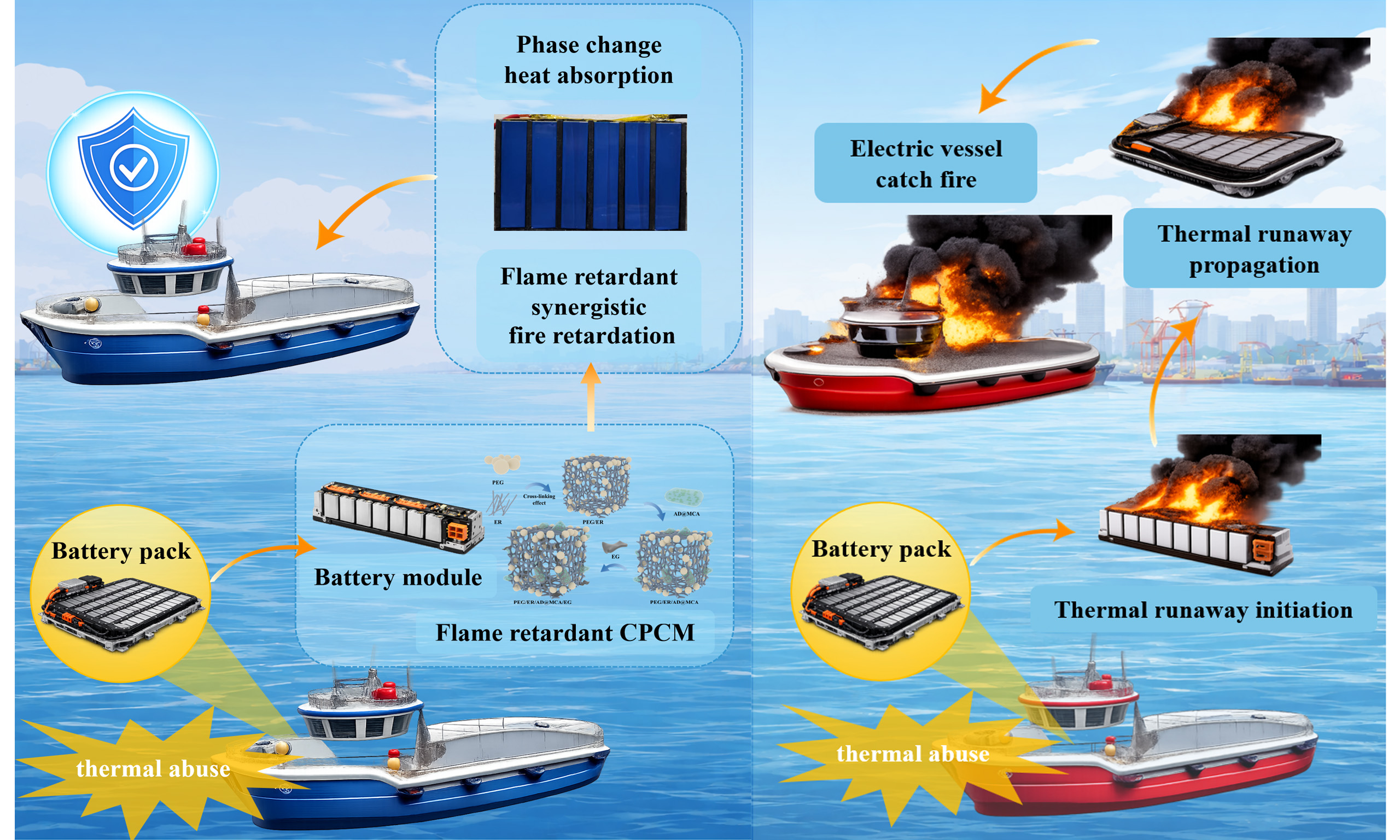
Flame-retardant composite phase-change materials (CPCMs) often face low flame-retardant efficiency and performance degradation after temperature aging owing to flame-retardant migration, limiting their use in electric vehicle battery packs and marine power systems. To address these challenges, we propose an innovative flame-retardant microencapsulated CPCM comprising ammonium polyphosphate (APP), dipentaerythritol (DPER), and melamine cyanurate (MCA) (AD@MCA) to improve battery module thermal safety. The microcapsules, prepared via in situ polymerization, enhance the flame-retardant efficiency and cycling stability of APP. This study compares the properties of CPCMs containing microencapsulated flame retardants and traditional physically blended flame retardants before and after thermal aging. Results show that the synergistic effect between MCA and DPER in the microencapsulated structure markedly improves the flame-retardant efficiency and cycling stability of APP. Furthermore, CPCMs containing microencapsulated flame retardants exhibit excellent battery thermal management performance and delay thermal runaway trigger times. This study presents a novel approach for developing multifunctional flame-retardant CPCMs for battery packs, addressing key challenges in battery thermal safety under extreme conditions.
Keywords
INTRODUCTION
As global energy crises intensify, demand for clean energy and energy storage technologies continues to rise[1,2]. Lithium-ion batteries have been widely adopted in consumer electronics and electric transportation because of their high energy density, moderate cost, and environmental compatibility[3-5]. However, thermal management remains a major challenge. During operation, especially under high-power and long-duration conditions, lithium-ion batteries produce considerable heat. If this heat is not dissipated promptly, the battery’s internal temperature may rise to dangerous levels[6,7]. Such temperature increases can adversely affect electrochemical performance, accelerate capacity fading, and ultimately shorten service life[8-10]. Critically, excessive heat accumulation increases the risk of thermal runaway, potentially causing catastrophic failures such as explosions or fires. These thermal management challenges have become critical barriers to the broader deployment and advancement of lithium-ion battery energy storage systems.
Battery thermal management systems (BTMSs) have been extensively developed to maintain lithium-ion batteries within a safe operating temperature range[11-13]. Among various strategies, phase-change material (PCM)-based cooling has garnered considerable attention because of its high heat storage capacity, compact structure, and zero additional energy consumption during operation[14-16]. Particularly, composite phase-change materials (CPCMs) demonstrate strong potential for battery modules owing to their enhanced structural integrity and thermal management capability.
However, CPCMs still face challenges such as poor thermal conductivity, leakage, and insufficient molding performance, especially in battery module applications[17-19]. Currently, many CPCM studies have focused on improving battery temperature control under normal operating conditions. Polyethylene glycol (PEG), a high-latent-heat PCM, shows great potential for energy storage and battery thermal management[19]. Chen et al.[20] proposed a solid-solid PCM based on polyurethane-crosslinked PEG2000, demonstrating excellent leak resistance, mechanical stability, and enhanced thermal conductivity, which effectively maintained lithium battery module temperatures within the optimal range during high-rate discharge. Yang et al.[21] developed a CPCM incorporating PEG2000, expanded graphite (EG), and AgNP-functionalized halloysite nanotubes (HNT@AP), achieving a thermal conductivity of 1.15 W/m·K and excellent leak resistance, keeping battery module temperatures below 60 °C during 3 C discharge under 35 °C ambient conditions. Moreover, incorporating high-thermal-conductivity fillers is an effective method for improving CPCM heat-transfer performance. EG, carbon fiber, and silver nanoparticles have been used to improve CPCM thermal conductivity, efficiently absorbing the phase matrix and offering high conductivity, gaining notable interest for battery module applications[22-25]. Kenganal et al.[26] investigated a CPCM by incorporating recycled waste-derived aerogels and foams as three-dimensional support structures, considerably enhancing thermal conductivity up to 1.18 W/m·K while maintaining excellent shape stability and thermal reliability over repeated thermal and photothermal cycles. Yang et al.[27] proposed a flexible CPCM combining n-docosane, thermoplastic polyester elastomers, and a hybrid of hexagonal boron nitride and carbon nanotubes, achieving room-temperature flexibility, enhanced thermal conductivity, and efficient temperature control of power batteries, with a peak temperature reduction of 11.93 °C during 5 C discharge. However, the flammability of PEG-based CPCMs still increases the fire risk and may cause battery module explosions. These limitations have restricted PCM application in BTMSs[28-30]. Therefore, developing multifunctional flame-retardant CPCMs has become crucial for practical applications[31]. Developing BTMSs that improve CPCM cycling stability in battery modules, particularly for thermal runaway suppression and flame-retardant performance, is urgently needed to enhance battery thermal safety[32].
For flame-retardant CPCMs used in battery thermal management, the major challenge lies in introducing flame retardants and maintaining their effectiveness during long-term thermal cycling while preserving the thermal-storage and heat-transfer performance of the composite[33,34]. Among commonly used intumescent flame retardants, ammonium polyphosphate (APP) shows considerable potential. At high temperatures, APP decomposition releases NH3 and N2, inhibiting combustion chain reactions by diluting the oxygen concentration. Meanwhile, the expanded carbon layer effectively blocks oxygen and heat diffusion[35-37]. However, its application in CPCMs remains limited by poor dispersion, insufficient matrix compatibility, and migration during repeated thermal cycling, all of which markedly compromise long-term flame-retardant stability[38]. Moreover, owing to its water solubility, APP gradually migrates and accumulates on the surface during thermal cycling, ultimately weakening CPCM performance[39]. To address these issues, dipentaerythritol (DPER) is used as a low-water-soluble, carbon-rich material. Its polyhydroxy structure substantially enhances APP carbonization efficiency and improves dispersion[40]. The thermal migration of APP has been addressed through coupling agent modification, surface treatment, and microencapsulation[41-43]. In addition, melamine cyanurate (MCA), formed through self-assembly of melamine and cyanuric acid via extensive hydrogen bonding, is nitrogen-rich[44]. At high temperatures, MCA decomposes to release abundant N2, diluting oxygen and combustibles in the combustion zone and thereby inhibiting flame spread[45].
To address the limitations of APP-based flame-retardant systems in CPCMs, such as poor dispersion, additive migration during thermal cycling, and insufficient long-term flame-retardant stability, the microencapsulation of APP and DPER with MCA has been proposed as a promising strategy. Through the coating structure, APP and DPER are effectively isolated within the protective MCA layer, substantially improving APP stability and preventing low flame-retardant efficiency and migration in CPCMs. Herein, an innovative multifunctional flame-retardant CPCM is proposed and applied to battery modules. PEG2000 is used as the PCM, EG as the porous material and high-thermal-conductivity additive, epoxy resin as the supporting skeleton, and AD@MCA as the flame retardant. Before and after thermal cycling, correlations among CPCM thermal conductivity, flame resistance, melting point, and latent heat are investigated. The gas-solid synergistic flame-retardant pathway affecting CPCM flame resistance is then discussed, followed by an analysis of how microencapsulation changes CPCM flame-retardant performance. Charge-discharge evaluation and thermal runaway simulation are subsequently performed on a lithium-ion battery module incorporating flame-retardant CPCMs. Therefore, by incorporating functional additives, these designed multifunctional CPCMs meet performance requirements, including customization, flame retardancy, high thermal conductivity, and long-term cycle stability. They regulate temperature under normal conditions before and after thermal cycling and maintain flame-retardant functionality under extreme conditions after thermal runaway.
EXPERIMENTAL
Materials
Polyethylene glycol (PEG2000; Guangzhou Muran Biochemical Technology Co., Ltd., China) with a melting point of 55 °C was selected as the PCM. Epoxy resin (ER; Shanghai Yuanye Bio-Technology Co., Ltd., China) served as the structural support matrix, while EG (Qingdao Degood Graphite Co., Ltd., China) was incorporated as a high thermal conductivity filler. DPER (Shanghai Aladdin Reagent Co., LTD., China) and APP (Shanghai Aladdin Reagent Co., Ltd., China) work together both as microcapsule core layers and flame retardants. Cyanuric acid (CA; Shanghai Aladdin Reagent Co., Ltd., China) and melamine (MA; Shanghai Aladdin Reagent Co., Ltd., China) functioned synergistically as microcapsule shell monomers and flame retardants.
Fabrication of flame retardant AD@MCA microcapsules
APP and DPER as the binary core materials were homogeneously dispersed in deionized water at a weight ratio of 5:1. The mixture was mechanically stirred at 3,000 rpm for 1 h under 25 °C. Subsequently, the resultant suspension was subjected to centrifugation, followed by vacuum drying to obtain powdered core material ammonium polyphosphate and dipentaerythritol (AD).
As illustrated in Figure 1A. the flame retardant microcapsules AD@MCA were fabricated through an in situ polymerization approach. Initially, an aqueous solution of the shell monomer CA was introduced into a three-neck flask and completely dissolved under continuous stirring at 400 rpm and 90 °C. Subsequently, the pre-synthesized core material AD was incorporated into the reaction system and homogenized through vigorous agitation for 3 h at 90 °C. A controlled addition process was then implemented, wherein a MA aqueous solution was slowly added to the well-mixed solution. The polymerization reaction was maintained at 90 °C for 4 h under a nitrogen atmosphere. The final product underwent sequential purification steps including ethanol washing, vacuum filtration, and lyophilization, yielding white solid microcapsules designated as AD@MCA.
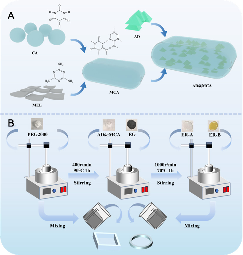
Figure 1. (A) Schematic illustration of AD@MCA flame retardant microcapsules; (B) schematic of the CPCM preparation route. MCA: Melamine cyanurate; CPCM: composite phase-change material; ER: epoxy resin; EG: expanded graphite; AD: ammonium polyphosphate and dipentaerythritol; MEL: melamine; CA: cyanuric acid.
Preparation of flame retardant CPCM
As schematically illustrated in Figure 1B, flame retardant CPCMs were synthesized using a melt blending methodology. The procedural steps are outlined as follows: Initially, polyethylene glycol (PEG2000) was thermally liquefied in an oil bath at 90 °C under continuous mechanical agitation at 800 rpm for 1 h. Subsequently, flame retardant microcapsules AD@MCA (or sequential additions of APP, DPER, and MCA) were proportionally incorporated into the molten PEG matrix and homogenized through vigorous stirring for 1 h at 90 °C under 400 rpm. Following this, EG was introduced into the hybrid system and uniformly dispersed via sustained agitation at 1,000 rpm for an additional hour at 70 °C. Finally, epoxy resin components ER-A and ER-B were sequentially added, followed by thorough mixing for 5 min at 70 °C under 1,000 rpm to achieve a uniform mixture. The resultant CPCM precursor was transferred into acrylic resin molds and subjected to thermal curing at 40 °C for 24 h to achieve structural stabilization. The detailed compositional parameters are systematically cataloged in Table 1.
The composition ratios of the CPCM
| Sample | PEE (wt%) | AD@MCA (wt%) | ||||
| PEG2000(wt%) | EG (wt%) | ER (wt%) | AD (wt%) | CA (wt%) | MA (wt%) | |
| PAD@M1 | 57.5% | 3.5% | 15% | 7.2% | 8.4% | 8.4% |
| PAD@M2 | 57.5% | 3.5% | 15% | 12% | 6% | 6% |
| PAD@M3 | 57.5% | 3.5% | 15% | 16.8% | 3.6% | 3.6% |
| APP (wt%) | DPER (wt%) | MCA (wt%) | ||||
| PADM1 | 57.5% | 3.5% | 15% | 6% | 1.2% | 16.8% |
| PADM2 | 57.5% | 3.5% | 15% | 10% | 2% | 12% |
| PADM3 | 57.5% | 3.5% | 15% | 14% | 2.8% | 7.2% |
Characterization
Morphology and chemical composition characterization
The static contact angle of the material was measured using a fully automated contact angle goniometer (OCA 100, DataPhysics Instruments GmbH, Germany). Powder samples were pressed into flat sheets under a pressure of 20 MPa for 30 min. Five replicates per formulation were tested to ensure statistical reliability. The microstructure and surface morphology of the raw materials were examined using scanning electron microscopy (SEM, SU8010, Hitachi High-Tech, Japan), with samples coated in gold to improve surface conductivity. Phase composition of the synthesized CPCMs was analyzed via X-ray diffraction (Ultima-IV, Rigaku Corporation, Japan). The X-ray diffraction (XRD) patterns were collected over a 2θ range of 10°-70° at a scanning rate of 10°/min under ambient conditions. To determine phase purity and crystallite size distribution, Rietveld refinement was carried out using Jade 9.0 software.
Thermal properties
The thermal properties of the CPCMs were characterized by differential scanning calorimetry using a Q2000 differential scanning calorimeter (TA Instruments, USA) and by the transient plane source method using a Hot Disk TPS 500s thermal constants analyzer (Hot Disk AB, Sweden). Further details on experimental procedures are provided in the Supporting Information.
Flame retardant properties
The fire resistance of CPCMs was assessed through multi-standard combustion tests, including vertical burning in compliance with UL-94 using a cone calorimeter (FTT, Fire Testing Technology, UK). Type V specimens (125 × 13 × 3.2 mm3) were vertically clamped and exposed to a methane flame (50 W ignition source). Each material's flammability rating (V-0 to V-2 classification) was determined as the average of five independent trials, with post-combustion dripping behavior recorded via high-speed imaging.
Limiting oxygen index (LOI, NETZSCH, Germany) measurements were performed following EN 45545-2:2013/A1:2015 guidelines using a Stanton Redcroft Flammability Test Apparatus (FTA) oxygen index analyzer. Combustion kinetics were further assessed using ISO 5660-compliant cone calorimetry (FTT Cone Calorimeter, Fire Testing Technology, UK) under an external heat flux of 35 kW/m2. Post-combustion residue analysis was performed using field-emission SEM (SU8010, Hitachi High-Tech, Japan). Char layers were sputter-coated with 5 nm platinum before imaging to enhance surface conductivity.
Further details on experimental procedures are provided in the Supplementary Materials 2.2.
Thermal management and thermal propagation measurements of battery module
A commercial lithium nickel manganese cobalt oxide (NMC) battery with a nominal capacity of 20 Ah was used as the test platform. Table 2 presents the specifications of both the battery and its module. Individual cells were welded and configured into modules using a 2P × 3S arrangement.
Battery cell and module specifications
| Parameters | Battery cells | Battery modules | |
| Voltage (V) | Charge | 4.2 | 12.6 |
| Discharge | 2.75 | 8.25 | |
| Current (A) | 1 C rate | 20 | 40 |
| 1.25 C rate | 25 | 50 | |
| 1.5 C rate | 30 | 60 | |
| Dimensions (mm) | Length | 70 | 70 |
| Width | 27 | 165.5 | |
| Height | 120 | 120 |
To investigate the thermal regulation performance of flame retardant CPCMs before and after thermal cycling, four types of battery modules PAD@M3 (PEG2000/ER/EG/AD@MCA3), PADM3, Aged PAD@M3, and Aged PADM3 were designed. They are denoted as PAD@M3- module, PADM3-module, Aged-PAD@M3-module, Aged-PADM3-module, respectively. The battery thermal management (BTM) system is shown in Figure 2A. Further, the Table 3 presents the charge and discharge test conditions and the corresponding thermal management evaluation results. Besides, the propagation behavior within the module was visually tracked using an infrared camera (TiS60, Fluke Corporation, USA). Additional test apparatus is illustrated in Figure 2B. Further details on experimental procedures are provided in the Supplementary Materials.
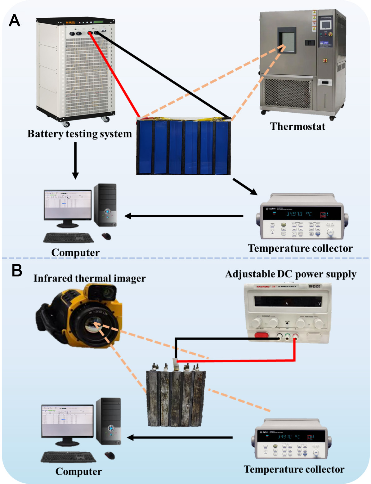
Figure 2. (A) Experimental platform for battery thermal management; (B) Thermal runaway simulation setup using flame retardant CPCM. CPCM: Composite phase-change material; DC: direct current.
Battery module charge-discharge conditions at various discharge rates
| Parameters | Voltage (V) | Current (A) | Time (min) | |
| CC-CV charge | 0.5 C rate | 8.25 | 20 | / |
| Rest | / | / | / | 30 |
| CC discharge | 1 C rate | 12.6 | 40 | / |
| 1.25 C rate | 12.6 | 50 | / | |
| 1.5 C rate | 12.6 | 60 | / | |
| Rest | / | / | / | 30 |
| Cycle | 10 times | / | / | / |
RESULTS AND DISCUSSION
Chemical composition and morphology
As shown in Figure 3A-F, pristine APP exhibits irregular large particles, while DPER displays finer morphology. Upon microencapsulation, the AD core is effectively coated by MCA, forming uniform AD@MCA microcapsules with a compact structure, indicating potential improvements in dispersion and surface compatibility. SEM images Figure 3C-F further differentiate the directly blended and microencapsulated systems. In Figure 3E and F, the PADM3 and Aged-PADM3 present indicated the aggregation by light green regions visibly on the surface, suggesting severe APP migration during thermal aging process. This poor dispersion and interfacial incompatibility result in a heterogeneous structure that compromises flame retardant efficiency. In contrast, PAD@M3 Figure 3C demonstrates uniform flame retardant distribution within the matrix with minimal surface accumulation. Even after thermal aging, the microcapsules maintain good interfacial contact and dispersion, confirming enhanced morphological stability [Figure 3D].
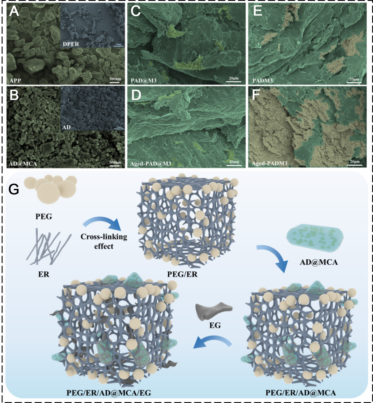
Figure 3. SEM images of (A) APP and DPER, (B) AD@MCA microcapsules and AD, (C) PAD@M3, (D) Aged-PAD@M3, (E) PADM3, (F) Aged-PADM3, (G) Structure diagram of flame retardant CPCM. SEM: Scanning electron microscopy; APP: ammonium polyphosphate; DPER: dipentaerythritol; MCA: melamine cyanurate; CPCM: composite phase-change material; PEG: polyethylene glycol; ER: epoxy resin; EG: expanded graphite; AD: ammonium polyphosphate and dipentaerythritol; PAD@M:PEG2000/ER/EG/AD@MCA.
Furthermore, the structural design of the CPCM with flame retardant functionality is schematically illustrated in Figure 3G. Initially, ER is formed through the reaction between ER-A and ER-B, followed by uniform blending with PEG2000. This measure helps to prevent the phase change material from leaking at high temperatures. To further improve its fire resistance, AD@MCA is incorporated as a synergistic flame retardant. Lastly, porous, worm-like EG is introduced as a thermally conductive additive to further optimize the composite material.
To investigate the influence of microencapsulated flame retardants on microstructure, the crystalline evolution of PEG2000/ER/EG (PEE), PADM3, and PAD@M3 before and after 200 thermal cycles is analyzed by XRD, as shown in Figure 4A. PEE exhibits typical diffraction peaks of orthorhombic PEG2000 at 19.1° and 23.7°. For PADM3, two additional peaks appear at 14.5° and 15.3°, which is assignable to the (200) and (110) crystal planes, respectively, indicating that direct blending induces local crystalline aggregation and disturbs the original crystallization behavior of the matrix. In contrast, there is no additional diffraction peaks are observed in PAD@M3, suggesting that microencapsulation improves flame-retardant dispersion and suppresses formation of new crystalline phases.
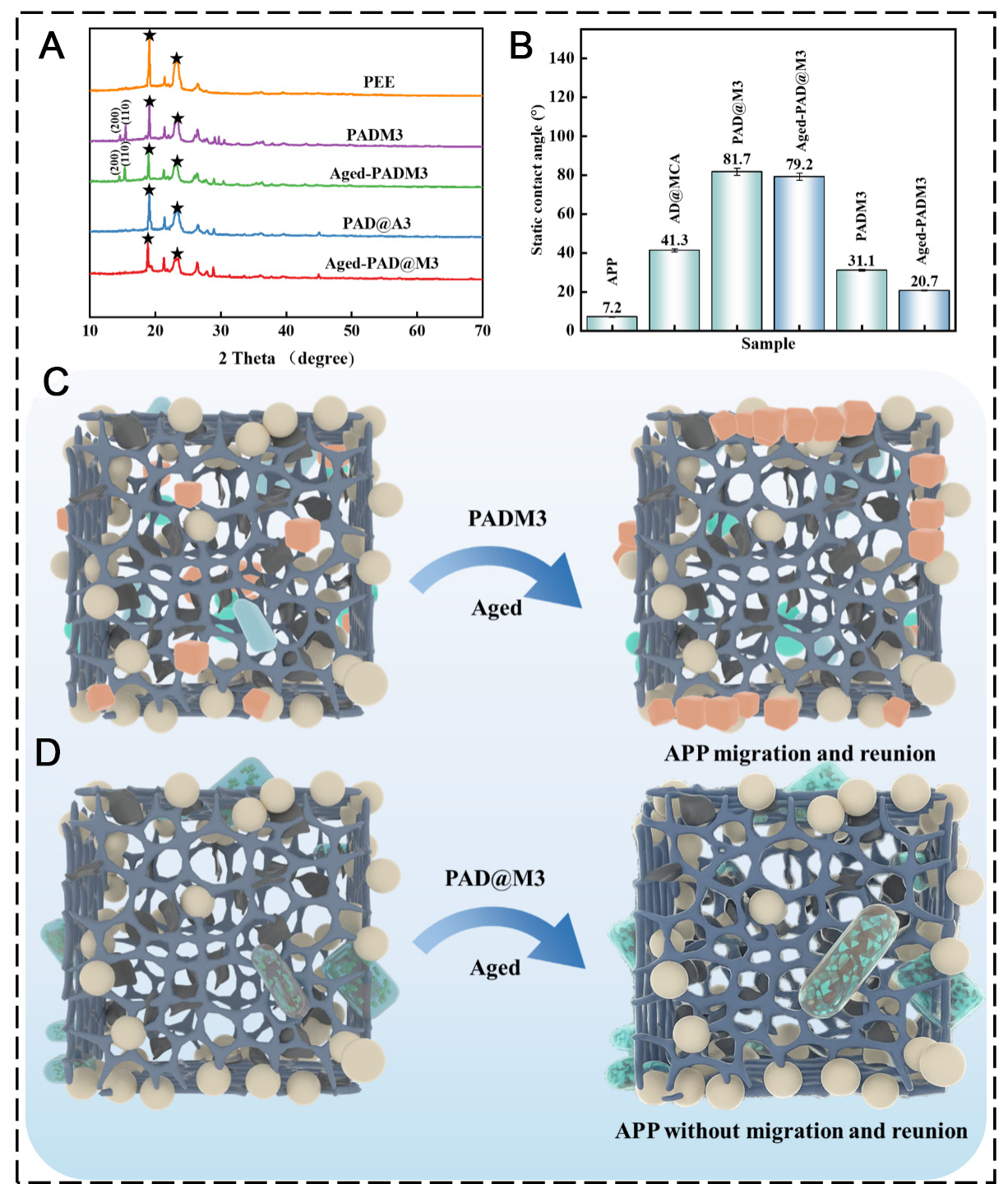
Figure 4. (A) XRD spectra of CPCM, (B) Static contact angles of flame retardants and CPCM samples. Error bars represent the standard deviation (SD) of five repeated measurements performed for each sample, Schematic diagram of the migration effect of (C) PADM3, (D) PAD@M3. CPCM: Composite phase-change material; MCA: melamine cyanurate; APP: ammonium polyphosphate; AD: ammonium polyphosphate and dipentaerythritol; XRD: X-ray diffraction; PEE: PEG2000/ER/EG; PAD@M: PEG2000/ER/EG/AD@MCA.
To quantitatively evaluate crystallization stability of PAD@M3 after thermal aging, the relative intensities of characteristic peaks at 19.1° and 23.7° are compared before and after 200 thermal cycles. After aging, the peak intensity at 19.1° decreases from 121,355 to 112,593, corresponding to a 7.2% reduction, while that at 23.7° decreases from 97,449 to 89,634, corresponding to an 8.0% reduction. Despite this slight decrease, peak positions remain unchanged and overall profiles are preserved, indicating that the crystalline structure of PAD@M3 is only marginally affected by thermal aging. These results demonstrate that microencapsulation enhances structural stability and helps maintain long-range order of CPCMs during thermal cycling.
To assess how microencapsulation influences flame retardant polarity and interfacial stability in composites, this study compared the hydrophobicity of APP and AD@MCA, as illustrated in Figure 4B, and evaluated the properties of PADM3 and PAD@M3 systems. Results demonstrated that microencapsulation significantly increased the contact angle of APP from 7.2° to 41.3°, indicating reduced polarity. The PAD@M3 exhibited a contact angle of 81.7°, which remained at 79.2° after thermal aging, confirming that AD@MCA effectively suppressed flame retardant migration and enhanced aging resistance through stable interfacial structures. In contrast, the direct blended PADM3 showed a contact angle of only 31.1°, which further dropped to 20.7° post-aging due to APP migration-induced surface polarity increase. These findings verify that microencapsulation has improved hydrophobicity stability and thermal aging tolerance by reducing polarity and enhancing dispersion, while direct blending leads to rapid performance degradation from interfacial instability. As shown in Figure 4C, the directly blended PADM3 experienced hydrophilic APP migration to the surface during aging, leading to structural degradation and compromised performance. In contrast, Figure 4D reveals that the encapsulated AD@MCA effectively suppressed APP migration and surface accumulation due to the physical barrier provided by the hydrophobic MCA.
Thermodynamic properties
To examine how microencapsulated and directly blended flame retardants affect the thermal conductivity of CPCMs, the conductivity variations of PADM3, and PAD@M3 before and after 200 thermal cycles are measured using the transient plane heat source method. Thermal conductivity tests in Figure 5A show that the microencapsulated systems consistently demonstrate higher thermal conductivity than their blended counterparts. After thermal cycling, the thermal conductivity of the microencapsulated system sample Aged-PAD@M3 decreased to 1.11 W/m·K, while that of the blend system Aged-PADM3 decreased sharply to 0.88 W/m·K. The excellent cycle stability of the thermal conductivity of the microencapsulated system sample may be since the microencapsulated AD@MCA reduces the formation of voids and maintains the integrity of the EG network by inhibiting the migration of flame retardants.
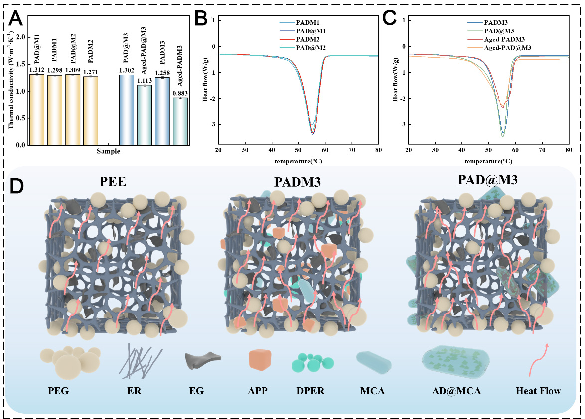
Figure 5. (A) Thermal conductivity of different CPCM samples. Error bars represent the standard deviation (SD) of five independent measurements performed for each sample, (B) DSC heating curves and (C) cooling curves of different CPCM, (D) Schematic diagrams of the heat conduction mechanisms in PEE, PADM3, and PAD@M3. CPCM: Composite phase-change material; PEG: polyethylene glycol; ER: epoxy resin; EG: expanded graphite; ammonium polyphosphate; DPER: dipentaerythritol; MCA: melamine cyanurate; AD: ammonium polyphosphate and dipentaerythritol; DSC: differential scanning calorimeter; PEE: PEG2000/ER/EG.
Differential Scanning Calorimeter (DSC) analysis Figure 5B and C shows that all samples exhibit endothermic peaks in the range of 40-60 °C, corresponding to the PEG solid-liquid phase transition process. Before aging, the latent heat value of the microencapsulated system samples is 5.3%-7.3% higher than that of the blended system samples. Specifically, the latent heat of the blended samples PADM1, PADM2, and PADM3 are 97.84 J/g, 96.13 J/g, and 95.15 J/g, respectively, while the latent heat values of the corresponding microencapsulated system samples are increased to 103.04 J/g, 102.75 J/g, and 102.14 J/g, respectively. This is likely due to the restriction imposed by AD@MCA on PEG chain mobility. After 200 thermal cycles, the latent heat of the blend system drops to 74.12 J/g, with a corresponding change rate of 22.1%, while the microencapsulated system retains 84.21 J/g, showing a lower change rate of 17.5%. The high latent heat maintenance rate of the microencapsulation system may be due to the poor compatibility between APP and CPCM in the blending system, which leads to the migration and enrichment of APP after thermal cycling, in which the PEG is slightly degraded due to repeated heating, thereby reducing the reversible phase change enthalpy. On the other hand, microencapsulated flame retardants avoid degradation caused by direct contact by isolating APP and PEG, thereby delaying performance degradation.
To further clarify the role of microencapsulation on heat transfer, the heat conduction mechanism of PEE, PADM3, and PAD@M3 is schematically illustrated in Figure 5D. In the PEE sample, heat is mainly conducted through the interconnected EG skeleton. The PEG/ER matrix mainly occupies the pores of the EG framework and contributes relatively little to heat conduction. In contrast, the microencapsulated flame retardant AD@MCA in PAD@M3 can be more uniformly dispersed throughout the CPCM, reducing particle aggregation and interfacial defects. As a result, the continuity and integrity of the EG thermal conduction network are better preserved, allowing heat to be transferred more smoothly through the composite. Even after thermal cycling, the microcapsule structure can suppress flame-retardant migration and reduce the formation of voids, thereby maintaining a more stable and continuous heat conduction pathway than that in the directly blended system.
Flame retardant properties
To systematically evaluate the influence mechanism of microencapsulated flame retardants and direct blending flame retardants on the flame retardancy and aging stability of CPCM, based on the UL-94 vertical combustion test standard, nine groups of samples are tested for primary ignition and secondary ignition, and the flame spread, self-extinguishing time and damage degree are recorded. The test pictures are shown in the Figure 6A and Supplementary Figure 1. Experiments show that the PEE without flame retardant has completely ignited within 15 s after one ignition, and it is seriously damaged and cannot be self-extinguished at 35 s. PAD@M1 self-extinguished at 12 s after the first ignition and at 30 s after the second ignition, achieving a V-1 rating. PADM1 self-extinguished at 13 s after the first ignition but continued to burn until 22 s during the second ignition, failing to meet the UL-94 standard. PAD@M2 self-extinguished at 12 s and 20 s after the first and second ignitions, respectively, also rated as V-1. PADM2 self-extinguished at 18 s after the first ignition but failed to self-extinguish by 23 s after the second ignition. The PAD@M3 of the microencapsulated flame retardant self-extinguishes in 11 s after the first ignition and 11 s after the second ignition. The self-extinguishing time of Aged-PAD@M3 after aging is only extended to 12 s. Both PAD@M3 and Aged-PAD@M3 achieve a V-0 rating. The direct blending PADM3 needs 18 s to self-extinguish in the first ignition, but the second ignition continues to burn for 25 s and cannot self-extinguish until it is completely damaged. The combustion performance of Aged-PADM3 has significantly deteriorated after aging procedure. The flame spreads rapidly 2 s after one ignition, the flame is close to the top in 35 s, and almost completely burns and cannot self-extinguish in 45 s.
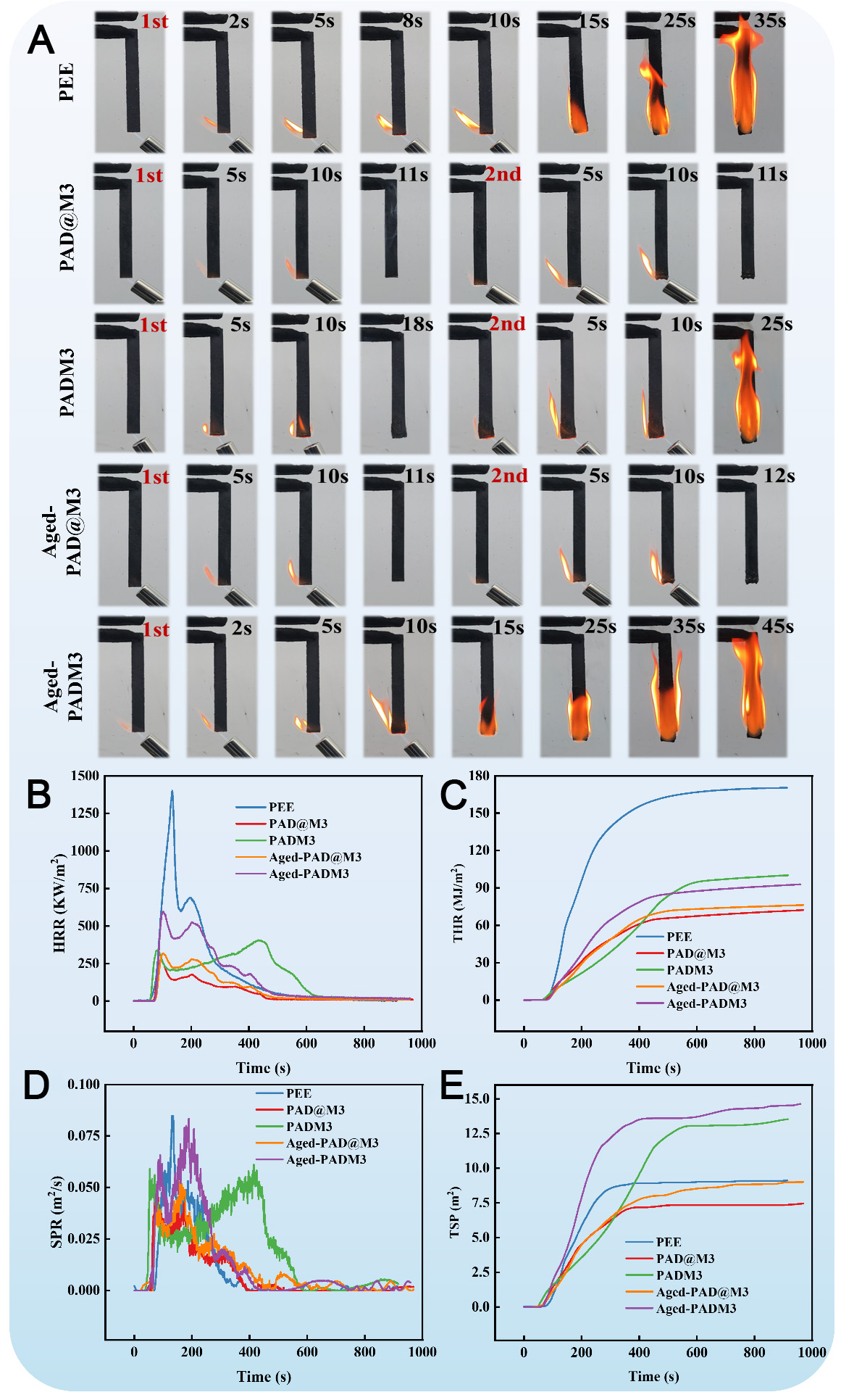
Figure 6. (A) Vertical combustion images of different CPCMs, (B-E) Cone calorimetry test results of (B) HRR, (C) THR, (D) SPR, and (E) TSP for various CPCM. CPCMs: Composite phase-change materials; HRR: heat release rate; THR: total heat release; SPR: smoke production rate; TSP: total smoke production; PEE: PEG2000/ER/EG; PAD@M: PEG2000/ER/EG/AD@MCA; PADM: PEG2000/ER/EG/APP/DPER/MCA.
In addition, the flame retardancy of different samples is quantitatively evaluated using LOI, total heat release (THR), heat release rate (HRR), total smoke production (TSP), and smoke production rate (SPR). The corresponding results are presented in Table 4 and Figure 6B-E. The results show that the LOI of the PEE substrate without flame retardant is only 19.2%. Its peak heat release rate (PHRR) reaches 1,400 kW/m2, the total heat release is 170 MJ/m2, and the smoke production rate and total smoke production are 0.085 m2/s and 9.1 m2, respectively.
LOI measurements, UL-94 vertical combustion grade, and cone calorimetry data
| Sample | UL-94 | LOI (%) | THR (MJ/m2) | HRR (kW/m2) | TSP (m2) | SPR (m2/s) |
| PEE | / | 19.2 | 170 | 1,400 | 9.1 | 0.085 |
| PAD@M3 | V-0 | 29.1 | 72 | 278.4 | 7.3 | 0.046 |
| PADM3 | / | 23.4 | 100 | 406.2 | 13.4 | 0.078 |
| Aged-PAD@M3 | V-0 | 28.8 | 76 | 317.8 | 8.9 | 0.052 |
| Aged-PADM3 | / | 21.9 | 92 | 594.3 | 14.3 | 0.083 |
Notably, the occurrence time of the PHRR differs significantly among the samples, reflecting variations in combustion kinetics. For PEE, the PHRR occurs at 134 s, indicating rapid heat release and intense combustion. Upon introducing microencapsulated flame retardants, the PHRR of PAD@M3 shifts to an earlier time of 87 s, while the peak intensity is significantly reduced. This suggests that although ignition occurs relatively quickly, the combustion process is effectively suppressed. In contrast, the blended system PADM3 exhibits a markedly delayed PHRR at 436 s, indicating prolonged heat accumulation and sustained combustion due to the formation of an unstable and ineffective char layer. After thermal aging, the PHRR of Aged-PAD@M3 is slightly delayed to 100 s, demonstrating good stability of combustion behavior. However, Aged-PADM3 shows its PHRR at 105 s, accompanied by a significant increase in heat release intensity, indicating deterioration in flame-retardant performance.
Meanwhile, the LOI of PAD@M3 increases to 29.1%, while the heat release rate and total heat release decrease to 278.4 kW/m2 and 72 MJ/m2, respectively, and the smoke production rate and total smoke production are reduced to 0.046 m2/s and 7.3 m2. After aging process, Aged-PAD@M3 maintains a high LOI of 28.8%, with only a slight increase in heat release rate to 317.8 kW/m2, confirming its superior flame-retardant stability. In contrast, PADM3 shows limited improvement, with an LOI of 23.4%. After aging process, the LOI further decreases to 21.9%, accompanied by increases in heat release rate to 594.3 kW/m2 and total smoke production to 14.3 m2. Thus, the PAD@M3 with the microencapsulated structure exhibits better flame retardancy and cycling stability.
Residual carbon analysis
To assess the flame retardant properties of CPCMs, carbon residue morphology after combustion is analyzed using cone calorimetry and scanning electron microscopy. The SEM characterization of combustion char residue Figure 7A-E shows that the char residue of PEE is honeycomb, the structure is loose, and there are a lot of cracks and holes, indicating a weak ability to block oxygen. PADM3 has a large number of carbon residue holes and poor structural uniformity. The microencapsulation system PAD@M3 has a dense surface of carbon residue and forms a continuous carbon layer. After aging, the Aged-PADM3 carbon layer of the blend system is loose and exfoliated, while the Aged-PAD@M3 carbon layer of the microencapsulation system still maintains a complete and dense structure.
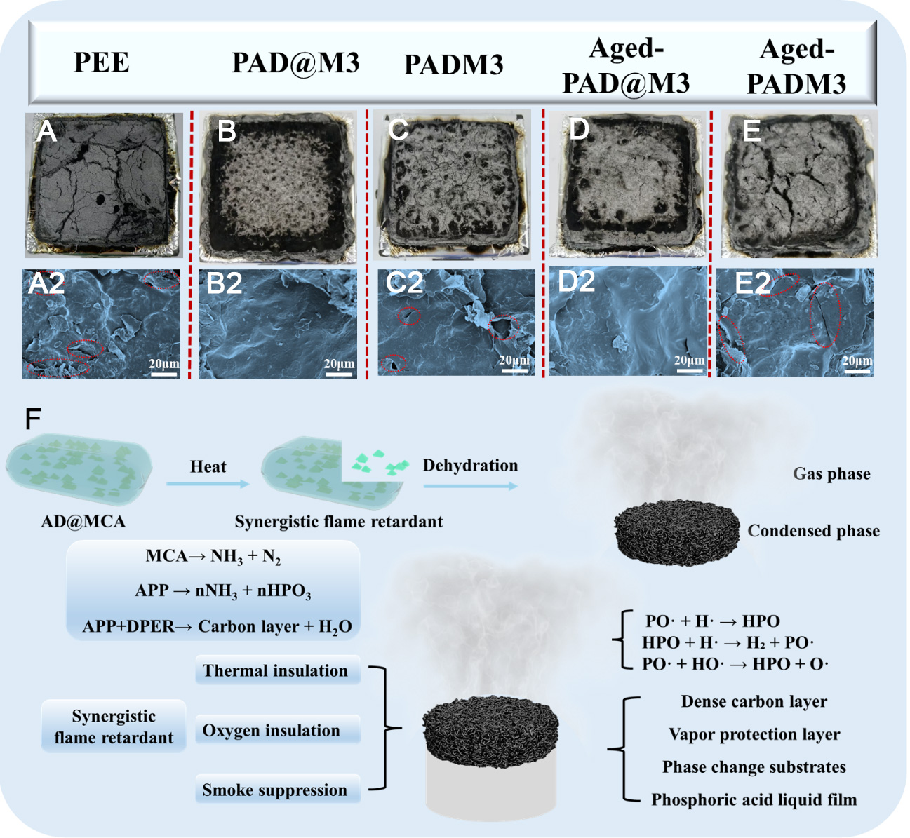
Figure 7. The post combustion char morphology of (A) PEE, (B) PAD@M3, (C) PADM3, (D) Aged-PAD@M3, (E) Aged-PADM3 and (F) flame retardant mechanism diagram of AD@MCA. MCA: Melamine cyanurate; APP: ammonium polyphosphate; DPER: dipentaerythritol; PEE: PEG2000/ER/EG; PAD@M: PEG2000/ER/EG/AD@MCA; PADM: PEG2000/ER/EG/APP/DPER/MCA; AD: ammonium polyphosphate and dipentaerythritol.
Figure 7F illustrates the flame retardant mechanism of microencapsulated AD@MCA. During the gas-phase flame retardant stage, the MCA shell decomposes and releases nitrogen gas, which dilutes the oxygen concentration in the gas phase and lowers the combustion temperature. In the condensed-phase flame retardant stage, internal APP decomposes to release phosphoric acid, which catalyzes DPER to dehydrate and carbonize, thus forming a dense char layer. The gas-phase flame retardant mechanism works by terminating combustion chains through reactions between the decomposition products of APP and reactive radicals such as H· and HO·. Compared to the conventional blends, the microencapsulation technology can not only significantly improve the synchronization of APP and DPER release but also enhance carbon layer formation through the synergistic release of all three flame retardant components, thereby achieving efficient flame retardancy.
Thermal management performance analysis
As shown in Figure 8A-C, the temperature distributions of different battery modules are illustrated. The PAD@M3 module exhibits a relatively uniform and overall lower temperature distribution. The aged Aged-PAD@M3 module shows a noticeable temperature rise, while the aged Aged-PADM3 module reaches the highest temperature, with heat distribution more concentrated.
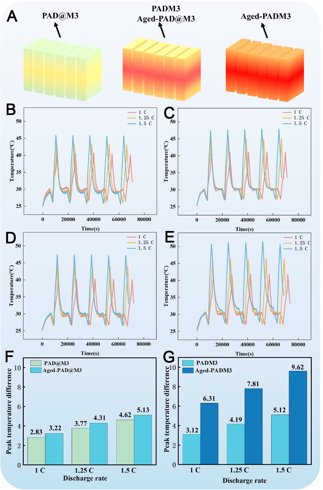
Figure 8. Battery thermal management performance: (A) schematic diagrams of the temperature distribution for different modules; Temperature curves of charge and discharge of the (B) PAD@M3 module; (C) PADM3 module; (D) Aged-PAD@M3 module; (E) Aged-PADM3 module; and (F and G) comparisons of the maximum temperature difference between fresh and aged modules. PAD@M: PEG2000/ER/EG/AD@MCA; PADM: PEG2000/ER/EG/APP/DPER/MCA.
To systematically assess the long-term impact of microencapsulated flame retardants on CPCM-based thermal management, four modular units are constructed in this study: PAD@M3, Aged-PAD@M3, PADM3, and Aged-PADM3, with the corresponding results shown in Figure 8B-G. After charging at 0.5 C under constant current and voltage, five charge-discharge cycles are conducted at 1 C, 1.25 C, and 1.5 C. The PAD@M3 module exhibits maximum temperatures of 40.5 °C, 43.1 °C, and 45.5 °C at the respective rates, with ΔTmax values of 2.83 °C, 3.77 °C, and 4.62 °C. In comparison, the blended PADM3 module shows higher maximum temperatures of 40.6 °C, 44.3 °C and 47.8 °C, and corresponding ΔTmax values of 3.12 °C, 4.19 °C, and 5.12 °C. After aging, the Tmax of the microencapsulated aging group Aged-PAD@M3-Module increases to 47.4 °C at 1.5 C, and the ΔTmax is 5.13 °C, which is 11.0% higher than that of the unaged sample. The Tmax of the Aged-PADM3 module in the blended aging group reaches 51.5 °C, with a ΔTmax of 9.62 °C - an 87.9% increase compared to the unaged sample. Further analysis shows that ΔTmax in the microencapsulated group rises by 63.3% under discharge rates from 1 C to 1.5 C, slightly below the 64.1% increase observed in the blended group. Notably, the performance degradation of the microencapsulated group after aging is only 12.5% that of the blended system. The above results show that the microencapsulated flame retardant reduces the Tmax of the material by 6.0 °C and the ΔTmax by 53.1% at 1.5 C discharge, and still maintains excellent thermal stability and long-term reliability after aging.
Thermal runaway analysis of simulated battery
To evaluate the thermal safety of CPCMs under extreme conditions, the thermal response characteristics of the four module configurations are investigated through staged heating experiments combined with infrared thermal imaging, as shown in Figure 9A-D. According to temperature evolution behavior, the thermal propagation process can be divided into three stages based on the moments when different heating plates first reach 70 °C. Specifically, Stages I, II, and III correspond to the times when heating plate No. 1, heating plates No. 2 and No. 3, and heating plates No. 4 and No. 5 first reach 70 °C, respectively. The corresponding stage transition times for the PAD@M3 module are 224 s, 833 s, and 1,957 s, while those for the PADM3 module are 181 s, 502 s, and 1,763 s, respectively. After thermal aging, the corresponding transition times for the Aged-PAD@M3 and Aged-PADM3 modules are 160 s, 597 s, and 2,100 s, and 160 s, 535 s, and 1,616 s, respectively. These results indicate that the microencapsulated flame-retardant system effectively delays heat propagation from the central trigger region to adjacent and edge regions.
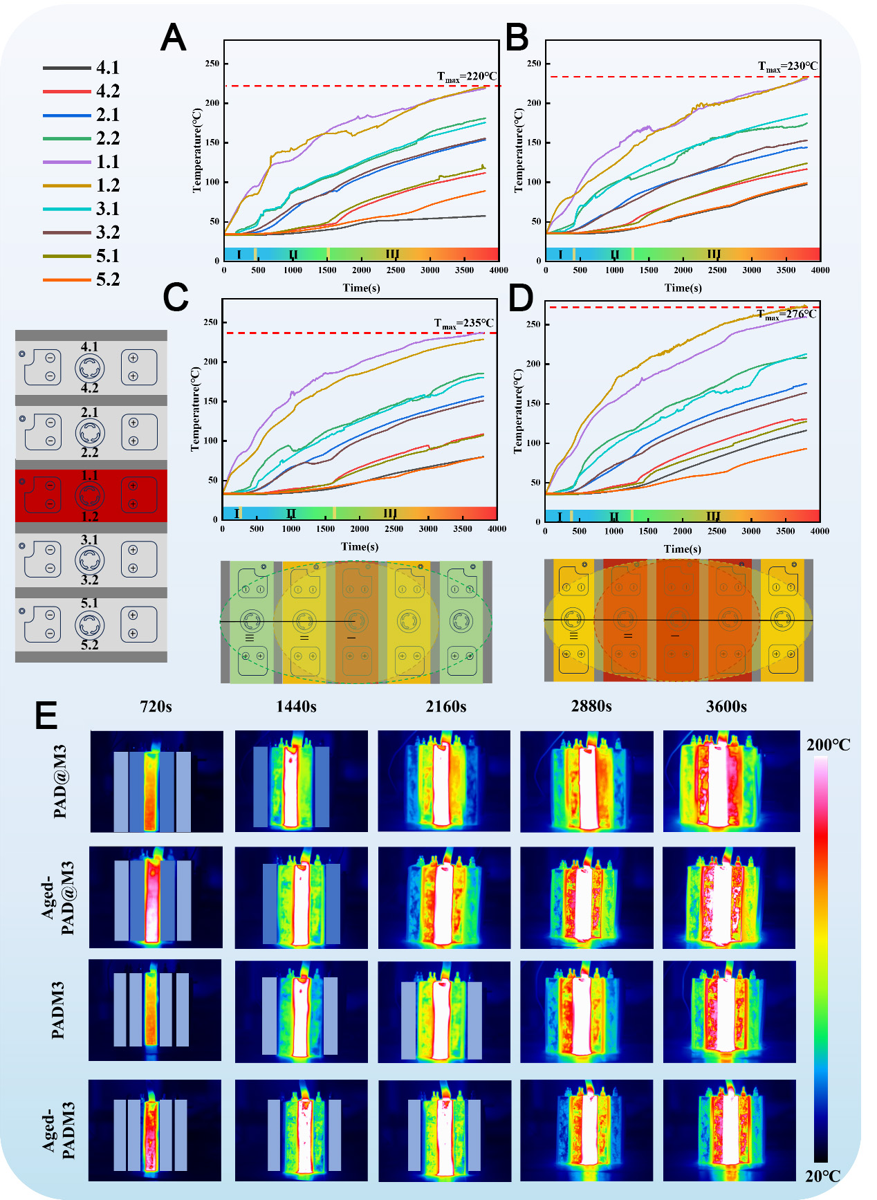
Figure 9. Thermal runaway change curve: (A) PAD@M3-module, (B) PADM3-module, (C) Aged- PAD@M3-module, (D) Aged-PADM3-module and (E) Infrared thermal imaging of different modules. PAD@M: PEG2000/ER/EG/AD@MCA; PADM: PEG2000/ER/EG/APP/DPER/MCA.
In Stage III, the times at which heating plates No. 4 and No. 5 reach their peak temperatures in the PAD@M3 module are delayed by approximately 200 s compared with those in the PADM3 module under identical heating conditions, confirming the superior thermal buffering capability of the microencapsulated system. Correspondingly, the maximum temperature of the PAD@M3 module in Stage III is 220 °C, lower than the 230 °C observed for the PADM3 module. After thermal aging, the maximum temperature of the Aged-PAD@M3 module increases to 235 °C, whereas that of the Aged-PADM3 module rises sharply to
The delayed thermal runaway propagation of the microencapsulated CPCM is mainly attributed to its higher latent heat retention. This allows the CPCM to absorb a greater amount of thermal energy during the phase change process, thereby extending the thermal buffering duration and effectively retarding the propagation of thermal runaway from the central heating plate to the outer region.
To further analyze the inhibition mechanism of different CPCMs on the thermal runaway (TR) of battery modules, this study focuses on the thermal resistance evolution of the PAD@M3-Module experimental group and its aging group, the PADM3-Module blending group and its aging group, and explores their differential heat transfer paths. It is found that the CPCM will form a dynamic thermal resistance network due to the phase transition during the thermal runaway process. In the initial stage, the direct contact between the CPCM and the heating plate causes heat conduction, and its thermal resistance characteristics and energy conservation relationship can be described by Formulas (1) and (2), respectively[46]. In the formula, Rpcm,s characterizes the solid-phase thermal resistance of CPCM, δs and λs are the material thickness and thermal conductivity, Mbattery and Cp,battery corresponds to the battery mass and specific heat capacity parameters.
When TR is initiated by the No.1 heating plate, the CPCM absorbs heat and undergoes a solid-liquid transition. The liquid layer gradually forms at the heating interface and introduces the liquid thermal resistance Rpcm,l. At this stage, the system’s thermal resistance and energy conservation equations are updated as shown in Formulas (3) and (4), where the thicknesses of the liquid layer (δl) and the remaining solid layer (δs) are dynamically coupled.
With the continuous development of thermal runaway, the molten CPCM is separated from the shaped skeleton to form an air gap interface, and the heat transfer mode is transformed into thermal radiation dominance. The radiation thermal resistance Rrad is quantified by Formula (5), and the corresponding energy conservation equation is adjusted to Formula (6). In the formula, A is the effective radiation area, ε is 0.04, which is the surface emissivity of the material, and δ is the Stefan-Boltzmann constant (5.67 × 10⁻⁸ W·m-2·K-4).
Infrared thermal imaging analysis reveals significant spatial temperature gradients during thermal runaway, as shown in the cloud map in Figure 9E. In the PAD@M3-Module at 2,880 s, the middle area of the No.1 heating plate is white, while the No.2 and No.3 plates are yellow-green with small red areas. In contrast, in the PADM3-Module, Aged-PADM3-Module, and the Aged-PAD@M3-Module, at 2,880 s, the middle area of the No.1 plate remains white, while the No.2 and No.3 plates are predominantly red.
The enhanced thermal buffering of the PAD@M3-Module and Aged-PAD@M3-Module is attributed to their higher latent heat, which absorbs more energy and delays the temperature rise at the center cells. Experiments show that the microencapsulation technology reduces the peak temperature of thermal runaway by 18.5%, and the performance degradation after aging is only 12.5% of that observed in the blending system.
Comparative studies have demonstrated that the PAD@M3 module markedly enhances BTM efficiency via a multi-level thermal resistance coordination mechanism. This design strategy, integrating temperature regulation and thermal runaway suppression, offers theoretical insights to advance high-safety BTM systems.
CONCLUSION
Flame-retardant CPCMs show considerable promise for battery thermal management and thermal runaway protection; however, their practical application remains limited by insufficient flame-retardant efficiency and performance degradation caused by flame-retardant migration during thermal aging. This study systematically investigates the effects of microencapsulated and traditional physically blended flame retardants on the structure, thermal properties, flame-retardant behavior, and thermal management performance of CPCMs.
The results demonstrate that microencapsulation effectively improves flame-retardant dispersion stability in CPCMs while maintaining structural and functional integrity during thermal aging. Compared with the directly blended system, the microencapsulated system exhibits better thermal reliability, flame-retardant durability, and battery thermal management stability. Notably, the microencapsulated flame-retardant design effectively enhances long-term cycling stability and improves adaptability under thermal aging conditions.
Overall, this study shows that microencapsulation provides a feasible route for simultaneously improving CPCM thermal management capability, flame-retardant performance, and long-term service stability. It also offers insightful guidance for designing high-safety PCMs for advanced BTMSs and a promising material strategy for improving the thermal safety of electric vehicles and marine power battery systems.
DECLARATIONS
Authors’ contributions
Writing - original draft, investigation, formal analysis: Zhao, G.
Writing - review & editing: Deng, J.
Investigation, methodology: Liang, B.; Wang, T.; Du, J.
Investigation, formal analysis: Luo, W.
Writing - review & editing, supervision: Liu, H.
Writing - review & editing, formal analysis: Yang, W.
Investigation: Yao, Y.; Guo, Z.
Writing - review & editing, methodology: Sun, Z.
Writing - review & editing, conceptualization, supervision: Li, X.
Availability of data and materials
The original contributions presented in this study are included in the article/Supplementary Materials. Further inquiries can be directed to the corresponding author(s).
AI and AI-assisted tools statement
Not applicable.
Financial support and sponsorship
This research was financially supported by National Natural Science Foundation of China (52576198) and Natural Science Foundation of Guangdong province (2026A1515010246).
Conflicts of interest
Sun, Z. is the Guest Editor of the special issue “Advanced Materials for Energy Storage and Conversion: Synthesis, Characterization and Application” of the journal Energy Materials. Sun, Z. was not involved in any steps of editorial processing, notably including reviewers' selection, manuscript handling, and decision making. The other authors declare that there are no conflicts of interest.
Ethical approval and consent to participate
Not applicable.
Consent for publication
Not applicable.
Copyright
© The Author(s) 2026.
Supplementary Materials
REFERENCES
1. Lee, W.; Kim, J. Cellulose nanofiber grafting and aluminum nitride deposition on the surface of expanded graphite to improve the thermal conductivity and mechanical properties of phase change material composites. Compos. Part. B. Eng. 2022, 230, 109526.
2. Sharma, A.; Abhinand, S.; Kothadia, H. Successive charging and discharging behaviour of a bio-organic sustainable phase change material and its instabilities. Chem. Eng. Sci. 2025, 307, 121354.
3. Ni, R.; Zhang, D.; Wang, R.; Xie, Z.; Wang, Y. Prevention and suppression effects of phase change material on thermal runaway in batteries. Case. Stud. Therm. Eng. 2023, 48, 103160.
4. Pilali, E.; Soltani, M.; Hatefi, M.; Shafiei, S.; Salimi, M.; Amidpour, M. Passive thermal management systems with phase change material-based methods for lithium-ion batteries: a state-of-the-art review. J. Power. Sources. 2025, 632, 236345.
5. Wei, H.; Zheng, Z.; Xu, X.; et al. Fabrication and building energy-saving performance evaluation of polyethylene glycol/polymethyl methacrylate/expanded graphite thermal enhanced shape-stable phase change material. Appl. Therm. Eng. 2024, 257, 124410.
6. Chen, Y.; Guo, X.; Shi, C.; Zhou, X.; Zou, D. Preparation of metal-based microencapsulated phase change material and its application in a battery for thermal management and thermal runaway protection. Compos. Part. B. Eng. 2025, 298, 112376.
7. Fathimathul Faseena, A.; Sreekumar, A. Advances, perspectives and challenges in phase change material based battery thermal management: a comprehensive review. J. Energy. Storage. 2025, 113, 115644.
8. Kim, J.; Bae, D.; Park, C.; Park, H. Pre-detection of thermal runaway in Li-ion 18650 batteries via temperature and voltage: the importance of temperature measurement location. Appl. Therm. Eng. 2025, 269, 125991.
9. Liu, Y.; Chen, Y.; Chang, Z.; Wu, X.; Jiang, Z.; Tang, S. Role of porous metal foam on temperature control and thermal runaway propagation of integrated battery thermal management systems. Appl. Therm. Eng. 2025, 267, 125712.
10. Wang, P.; Xu, C.; Huang, J.; Zhang, M.; Jiang, F.; Feng, X. Experimental and simulation study on internal thermal runaway development drives venting and flammable gas risk evaluate of lithium-ion battery. Appl. Energy. 2025, 385, 125545.
11. Gharehghani, A.; Rabiei, M.; Mehranfar, S.; et al. Progress in battery thermal management systems technologies for electric vehicles. Renew. Sustain. Energy. Rev. 2024, 202, 114654.
12. Hwang, F. S.; Confrey, T.; Reidy, C.; et al. Review of battery thermal management systems in electric vehicles. Renew. Sustain. Energy. Rev. 2024, 192, 114171.
13. Liu, J.; Yadav, S.; Salman, M.; Chavan, S.; Kim, S. C. Review of thermal coupled battery models and parameter identification for lithium-ion battery heat generation in EV battery thermal management system. Int. J. Heat. Mass. Transfer. 2024, 218, 124748.
14. Keyhani-asl, A.; Perera, N.; Lahr, J.; Hasan, R. Innovative hybrid battery thermal management system incorporating copper foam porous fins and layers with phase change material and liquid cooling. Appl. Therm. Eng. 2025, 268, 125848.
15. Najafi Khaboshan, H.; Jaliliantabar, F.; Abdullah, A. A.; Panchal, S.; Azarinia, A. Parametric investigation of battery thermal management system with phase change material, metal foam, and fins; utilizing CFD and ANN models. Appl. Therm. Eng. 2024, 247, 123080.
16. Lin, X.; Zhou, Z.; Liu, M.; et al. Thermal management performance and optimization of a hybrid system integrating liquid cooling and fin-enhanced phase change material for large-capacity energy storage battery pack. Energy. Convers. Manag. 2025, 336, 119889.
17. Zhang, W.; Zhang, J.; Zhang, G.; et al. A novel leak-proof thermal conduction slot battery thermal management system coupled with phase change materials and liquid-cooling strategies. Energies 2024, 17, 939.
18. Wang, J. X.; Mao, Y.; Miljkovic, N. Nano‐enhanced graphite/phase change material/graphene composite for sustainable and efficient passive thermal management. Adv. Sci. 2024, 11, 2402190.
19. Li, X.; Wang, J.; Wu, Z.; Cao, W.; Zhang, X. An energy saving strategy on the composite phase change material and spiral liquid cooling channel for battery thermal management. Renew. Energy. 2024, 227, 120529.
20. Chen, M.; Gong, Y.; Zhao, L.; Chen, Y. Phase change material with outstanding thermal stability and mechanical strength for battery thermal management. J. Energy. Storage. 2024, 104, 114565.
21. Yang, W.; Lin, R.; Li, X.; et al. High thermal conductive and anti-leakage composite phase change material with halloysite nanotube for battery thermal management system. J. Energy. Storage. 2023, 66, 107372.
22. Zhao, J.; Chen, Y.; Chen, M. Battery thermal management with a modified metal alloy/expanded graphite/paraffin composite phase change material. J. Energy. Storage. 2025, 113, 115652.
23. Chen, Y.; Tian, C.; Tu, Y.; et al. Paraffin/graphite/boron nitride composite as a novel phase change material for rapid heat absorption in battery thermal management technology. Int. J. Heat. Mass. Transfer. 2024, 235, 126214.
24. Cheng, G.; Wang, Z.; Wang, X.; He, Y. All-climate thermal management structure for batteries based on expanded graphite/polymer composite phase change material with a high thermal and electrical conductivity. Appl. Energy. 2022, 322, 119509.
25. B., K.; Pandey, A.; Saidur, R.; Tyagi, V. Energizing organic phase change materials using silver nanoparticles for thermal energy storage. J. Energy. Storage. 2023, 58, 106361.
26. Kenganal, S. S.; Sahoo, A. Ground tire rubber/activated carbon/expanded graphite aerogels and foams as support material for the preparation of polyethylene glycol composite phase change materials for thermal energy storage applications. J. Energy. Storage. 2024, 78, 109805.
27. Yang, J.; Chen, L.; Ou, J.; Li, W.; Wu, W. Room-temperature flexible composite phase change materials for enhanced battery thermal management. Appl. Therm. Eng. 2025, 265, 125667.
28. Chen, M.; Zhu, M.; Zhao, L.; Chen, Y. Study on thermal runaway propagation inhibition of battery module by flame-retardant phase change material combined with aerogel felt. Appl. Energy. 2024, 367, 123394.
29. Luo, W.; Zou, M.; Wang, J.; et al. Cross-linked polyurethane phase change materials based on multiple hydrogen bonds with excellent mechanical, flame retardant and energy storage properties for novel battery jackets. ACS. Sustainable. Chem. Eng. 2025, 13, 16497-508.
30. Liu, F.; Wang, J.; Wang, F.; et al. Battery thermal safety management with form-stable and flame-retardant phase change materials. Int. J. Heat. Mass. Transfer. 2024, 218, 124764.
31. Zhang, S.; Wang, R.; Du, Y.; et al. Inherently flame retardant and aging resistance rigid polyurethane foam by incorporating the synthesized polyhydroxy phosphonates. Compos. Commun. 2025, 53, 102246.
32. Li, Y.; Hu, S.; Fang, H.; Deng, Y.; Yang, C. Highly-efficient flame-retarding unsaturated polyester resin via the designation of an expansive flame retardant. Adv. Ind. Eng. Polym. Res. 2025, 8, 10-9.
33. Li, Y.; Zhu, Y.; Vallem, S.; et al. Flame-retardant ammonium polyphosphate/MXene decorated carbon foam materials as polysulfide traps for fire-safe and stable lithium-sulfur batteries. J. Energy. Chem. 2024, 89, 313-23.
34. Li, K.; Yuan, B. Developing flame-retardant properties into intrinsic phase change materials: a molecular design study inspired by phosphorus-nitrogen synergy. Chem. Eng. J. 2025, 509, 161287.
35. Chu, T.; Lu, Y.; Hou, B.; et al. Engineering amine-modified ammonium polyphosphate for enhancing flame retardancy and smoke suppression of vinyl ester resin. Constr. Build. Mater. 2025, 475, 141174.
36. Liu, Z.; Dai, M.; Hu, Q.; et al. Effect of microencapsulated ammonium polyphosphate on the durability and fire resistance of waterborne intumescent fire-retardant coatings. J. Coat. Technol. Res. 2018, 16, 135-45.
37. Zheng, P.; Zhao, H.; Li, J.; et al. Recent advances in constructing new type of epoxy resin flame retardant system using ammonium polyphosphate. J. Saf. Sci. Resil. 2024, 5, 179-93.
38. Li, F.; Wang, Y.; Lai, M.; Zhang, H.; Zhao, J. Recycling cenospheres to construct chitosan bonded-ammonium polyphosphate/dipentaerythritol hybrid geopolymer coatings for flame-retarding plywood. J. Mater. Res. Technol. 2023, 25, 3865-83.
39. Peil, S.; Mouhoubi, R.; Streekstra, R.; et al. Encapsulation of ammonium polyphosphate in lignin nanocontainers enhances dispersion and flame retardancy in polylactic acid Foams. ACS. Appl. Polym. Mater. 2024, 6, 6096-107.
40. Qin, Z.; Yang, R.; Zhang, W.; Li, D.; Jiao, Q. Synergistic barrier effect of aluminum phosphate on flame retardant polypropylene based on ammonium polyphosphate/dipentaerythritol system. Mater. Des. 2019, 181, 107913.
41. Wu, X.; Qin, Z.; Zhang, X.; et al. Micro-nanometer particle composition and functional design of surface nano-structured ammonium polyphosphate and its application in intumescent flame-retardant polypropylene. Nanomaterials 2022, 12, 606.
42. Sun, Q.; Wang, J.; Meng, X.; Zhang, J.; Yan, H. A novel high-efficient P/N/Si-containing APP-based flame retardant with a silane coupling agent in its molecular structure for epoxy resin. Chin. J. Chem. Eng. 2023, 55, 137-47.
43. Zhang, X.; Zhang, F.; Zhang, W.; Tang, X.; Fan, H. S. Enhance the interaction between ammonium polyphosphate and epoxy resin matrix through hydrophobic modification with cationic latex. Colloids. Surf. A. Physicochem. Eng. Asp. 2021, 610, 125917.
44. Wang, W.; Liu, Y.; Wang, Q. Synthesis of melamine cyanuric based flame retardant via hydrogen bond self-assembly and in-situ dispersion strategies for improving comprehensive performance of epoxy resin. Compos. Part. A. Appl. Sci. Manuf. 2024, 176, 107826.
45. Li, X.; He, Y.; Tang, D.; Liu, Y.; Wang, Q. Application of MCA-AlPi nitrogen-phosphorus synergistic flame retardant in nylon 11. J. Appl. Polym. Sci. 2025, 142, e57158.
Cite This Article
How to Cite
Download Citation
Export Citation File:
Type of Import
Tips on Downloading Citation
Citation Manager File Format
Type of Import
Direct Import: When the Direct Import option is selected (the default state), a dialogue box will give you the option to Save or Open the downloaded citation data. Choosing Open will either launch your citation manager or give you a choice of applications with which to use the metadata. The Save option saves the file locally for later use.
Indirect Import: When the Indirect Import option is selected, the metadata is displayed and may be copied and pasted as needed.
About This Article
Special Topic
Copyright

Data & Comments
Data
0


Comments
Comments must be written in English. Spam, offensive content, impersonation, and private information will not be permitted. If any comment is reported and identified as inappropriate content by OAE staff, the comment will be removed without notice. If you have any queries or need any help, please contact us at [email protected].