


Capillary slit induced graphene laminate films towards enhanced areal capacitive energy storage
 0
0 Abstract
This study presents a novel slit evaporation self-assembly method for fabricating freestanding sulfuric acid-treated reduced graphene oxide/commercial graphene films
Keywords
INTRODUCTION
Nowadays, the escalating demand for future flexible devices, micro-energy storage systems, smart textiles, and other surface-constrained applications has triggered a heightened focus on areal specific capacitance. This metric directly quantifies the performance of energy storage systems in terms of capacitance per unit area, which is crucial for optimizing the efficiency and functionality of these advanced technologies[1-4]. Graphene emerges as a highly promising electrode material for supercapacitors with ultrahigh areal specific capacitance due to its distinctive two-dimensional structure, large surface area, high conductivity, and excellent physicochemical stability[5-8]. Moreover, recent reports have demonstrated that properly engineered graphene-based architectures can exploit pseudocapacitive behavior and hierarchical structures to significantly improve both areal capacitance and cycling stability[9-11]. Nevertheless, the spontaneous clustering and re-stacking of graphene sheets often lead to decreased surface area and a porous structure with low density, limiting its efficacy in high-energy-density devices[12,13]. To address these challenges, the strategic design of layered-stacked graphene structures is proposed. This approach can effectively counteract sheet
There are diverse methods that showcase the ongoing efforts to advance the synthesis of layered-stacked graphene, aiming to improve capacitive performance and versatility[23-25]. For example, Xin et al. reported the precise control of the graphene sheet alignment and orientation order via microfluidics design, in which high thermal, electrical, and mechanical properties are realized[26]. Lee et al. fabricated graphene islands using the chemical vapor deposition method and then stacked the graphene islands and reduced GO (rGO) layer by layer to form large-scale layered graphene, which exhibited a long cycling lifetime and high power density[27]. Moreover, to further expand the extent of the intrinsic capacitance of graphene building units, creating pores, heteroatom doping, and functionalization are rationally designed[28-32]. These strategies can not only improve the utilization of the materials but also provide additional redox-active sites (pseudocapacitance). Unlike traditional electric double-layer capacitors, which rely solely on the physical adsorption of charge at the electrode surface, pseudocapacitors combine this process with the chemical redox reactions of pseudocapacitive materials. This dual mechanism enables a higher charge storage capacity[33,34]. However, the active sites involved in redox reactions within pseudocapacitors often exhibit poor chemical stability and durability over extended cycling periods. This limitation leads to a significant drawback in supercapacitors, as they are unable to maintain their performance during prolonged use[29].
Oxygen-containing groups on graphene enhance pseudocapacitance by acting as redox-active sites, boosting energy storage in supercapacitors[35-37]. Functional groups such as hydroxyl (C-OH), carboxyl (O-C=O), and epoxy (C-O-C) can significantly influence the electronic and electrochemical properties of graphene. For instance, hydroxyl and carboxyl groups are known to be active oxygen-containing functional groups that facilitate rapid charge transfer and interaction with the electrolyte[38]. These groups can participate in redox reactions, thereby increasing the number of available redox sites and improving the overall capacitance and energy storage capabilities of the material[39]. On the other hand, epoxy groups are considered inert and can impede charge transfer, limiting the electrochemical performance. Therefore, converting these inert groups into more active forms - such as hydroxyl and carboxyl groups - through appropriate pre-treatment and thermal reduction processes will be beneficial for enhancing the electrochemical performance[40]. However, further research is required to optimize the conversion processes for these inert groups, and to comprehensively evaluate the performance of modified graphene in various electrochemical applications.
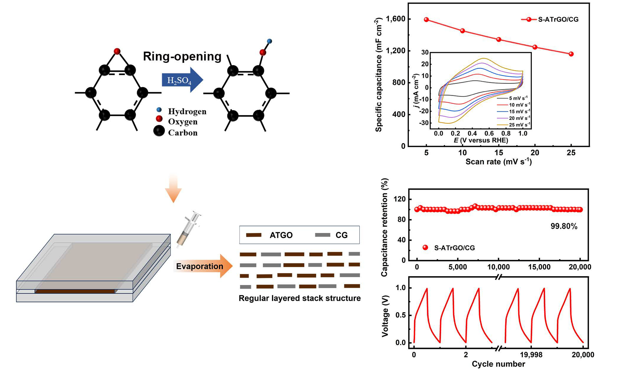
Herein, we report the design of freestanding graphene laminate films, which are achieved through capillary slit-assisted self-assembly of sulfuric acid-treated graphene oxide (ATGO) sheets with commercial graphene (CG), as shown in Figure 1. In brief, a mixed suspension of ATGO and CG was first prepared, and injected into a capillary slit constructed by two glass plates. Upon heating, the ATGO and CG can self-assemble to form uniform laminated macroscopic structures under the action of π-π stacking effect and electrostatic attraction. The ATGO/CG film was then subjected to heat treatment in an Ar atmosphere, yielding the freestanding laminated graphene film [denoted as sulfuric acid-treated reduced graphene oxide
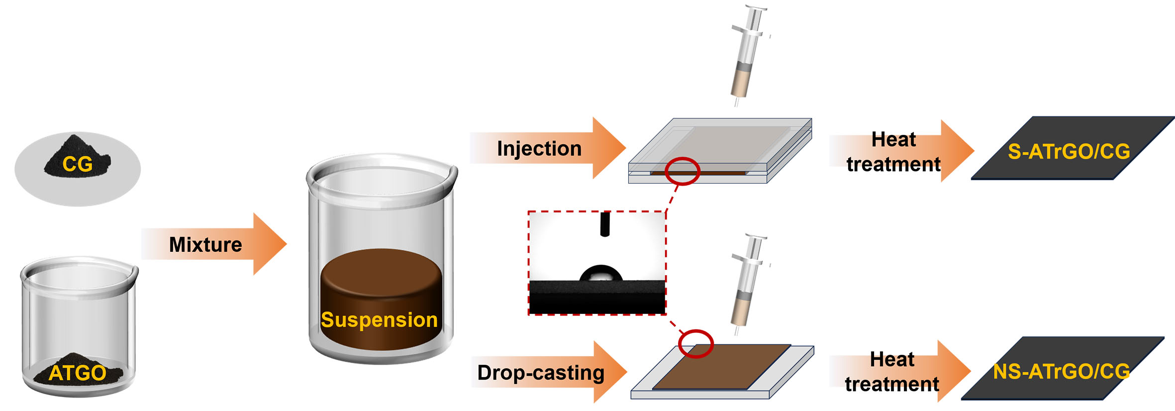
Figure 1. Schematic illustration of graphene electrode preparation by slit evaporation self-assembly method and conventional coating method. Inset shows the contact angle of the slit mold. CG: Commercial graphene; ATGO: acid-treated graphene oxide; S-ATrGO: sulfuric acid-treated reduced graphene oxide; NS: non-slit.
EXPERIMENTAL
Materials
Graphite powder (325 mesh) and 95% ethanol were purchased from Aladdin Reagent Co., Ltd. (Shanghai, China). NaNO3, H2SO4, KMnO4, H2O2 and HCl were supplied by China Medicine Co. Ultrapure water
Preparation of ATGO
The GO was synthesized using the Hummers method[41]. The obtained GO was dispersed in 1 M H2SO4, treated with ultrasonic vibration for 30 min, and subsequently stirred mechanically for 24 h. Afterward, the suspension was washed by repeated centrifugation until a neutral pH was reached, and then freeze-dried for 72 h to yield ATGO[42].
Preparation of S-ATrGO/CG and NS-ATrGO/CG
The ATGO was configured into a suspension with a concentration of 22 mg mL-1, and CG powder with a mass fraction of 75 wt.% was added to it. Take 2.5 mL of the prepared mixed solution and drop it into a glass mold. The complete slit evaporation self-assembly and coating system was placed in a vacuum drying oven and dried at 60 °C for 48 h. The resulting film, denoted as slit-assisted ATGO/CG (S-ATGO/CG), was then subjected to thermal reduction together with the non-slit-assisted ATGO/CG (NS-ATGO/CG) film. Both films were placed in a tube furnace energized with high-purity argon gas and heated to 350 °C at a heating rate of 2 °C min-1, held for 30 min and then cooled to room temperature in the furnace to obtain
Materials characterization
The surface and cross-sectional morphology of the samples were observed using scanning electron microscopy (SEM, Supra 55; Carl Zeiss, Oberkochen, Germany) and laser confocal microscopy (LEXT OLS3000; Olympus, Tokyo, Japan). The crystal orientation consistency was analyzed by wide-angle X-ray scattering (WAXS, Xeuss 2.0; Xenocs, Grenoble, France) to investigate the lamellar arrangement of graphene. To determine the degree of orientation in thin-film crystals, the one-dimensional integrated curve was calculated using
where Δφ is the full width at half maximum of the intensity peak, I(φ) is the light intensity per unit area,
Electrochemical performance measurement
The electrochemical performance was analyzed using an electrochemical workstation (CHI760E; CH Instruments, Austin, TX, USA). The as-prepared electrodes were tested in a three-electrode system using
To further validate practicality, the electrochemical performance of the S-ATrGO/CG//S-ATrGO/CG CR2032 coin cell symmetric supercapacitor (SSC) was characterized by assembling it with a separator (GF/D6227; Olegeeino, China) soaked in 1 M H2SO4 aqueous solution and sandwiched between the cathode and anode electrodes. All tests were conducted at room temperature. The areal capacitance Carea,electrode and volume capacitance Cvolumn,electrode were calculated using
The energy density (EA, Wh cm-2) and power density (PA, W cm-2) were calculated using
where I is the current density, v is the scan rate, ΔV is the potential window, Selectrode is the area of single electrode, Velectrode is the volume of single electrode, and Δt is the discharging time. The thickness of the electrode films was directly measured from the SEM images of the cross-sections. The reported values are the averages of at least five measurements taken at different spots across the cross-section. The volumetric capacitance was then calculated using this thickness and the electrode area (1 cm2).
The exact ratio between diffusion-controlled and capacitive contributions can be quantified based on
where
RESULTS AND DISCUSSION
The surface of ATGO is rich in oxygen-containing functional groups, which can serve as direct binding sites for CG as well as grafting sites for CG. These groups can interact with the defects and edges on the CG. Additionally, ATGO and CG can generate electrostatic attraction and van der Waals forces, thereby promoting their interfacial interaction, without the addition of non-active additives (such as binder or conductive agents)[45]. Meanwhile, the ATGO still retains sp2 conjugated domains with aromatic rings, which can interact with the sp2 regions of CG through π-π stacking and van der Waals forces. Therefore, the sp3 regions in ATGO provide chemical bonding/anchoring effects, while the sp2 regions maintain π-π and van der Waals interactions with CG. The coexistence of these interactions ensures that the composite film possesses strong interfacial adhesion and efficient electron transport capability. Our recent research results indicate that the use of capillary slits constructed from aluminum foil enables the formation of smooth and stacked graphene films covering the surface of the aluminum foil[46]. Graphene suspensions exhibit a characteristic tendency to align along the liquid/gas interface, and self-supporting graphene electrodes can be prepared by adjusting the contact angle of the slit mold. The XRD patterns of CG are shown in Supplementary Figure 1. From the pattern, it can be observed that there is only one peak at 2θ = 26.4°, indicating that CG is a pure graphene structure.
The cross-sections of the S-ATrGO/CG and NS-ATrGO/CG films are depicted in Figure 2A, in which both films exhibit a dense layered structure with a thickness of approximately 120 μm. When the S-ATrGO/CG film is dried within the slit, the combined influence of capillary force and thermal convection facilitates uniform deposition of graphene sheets. However, as for NS-ATrGO/CG, the suspension was drop-casted directly on the glass mold, exhibiting a slight upward flow during the evaporation process, resulting in a relatively disordered appearance. Confocal microscopy was used to further characterize the topography of the two films. As shown in Figure 2B, the roughness average (Ra) of S-ATrGO/CG is 4.83 μm, with a maximum height variation of 27.50 μm, and no obvious defects or wrinkles are observed. The Ra of
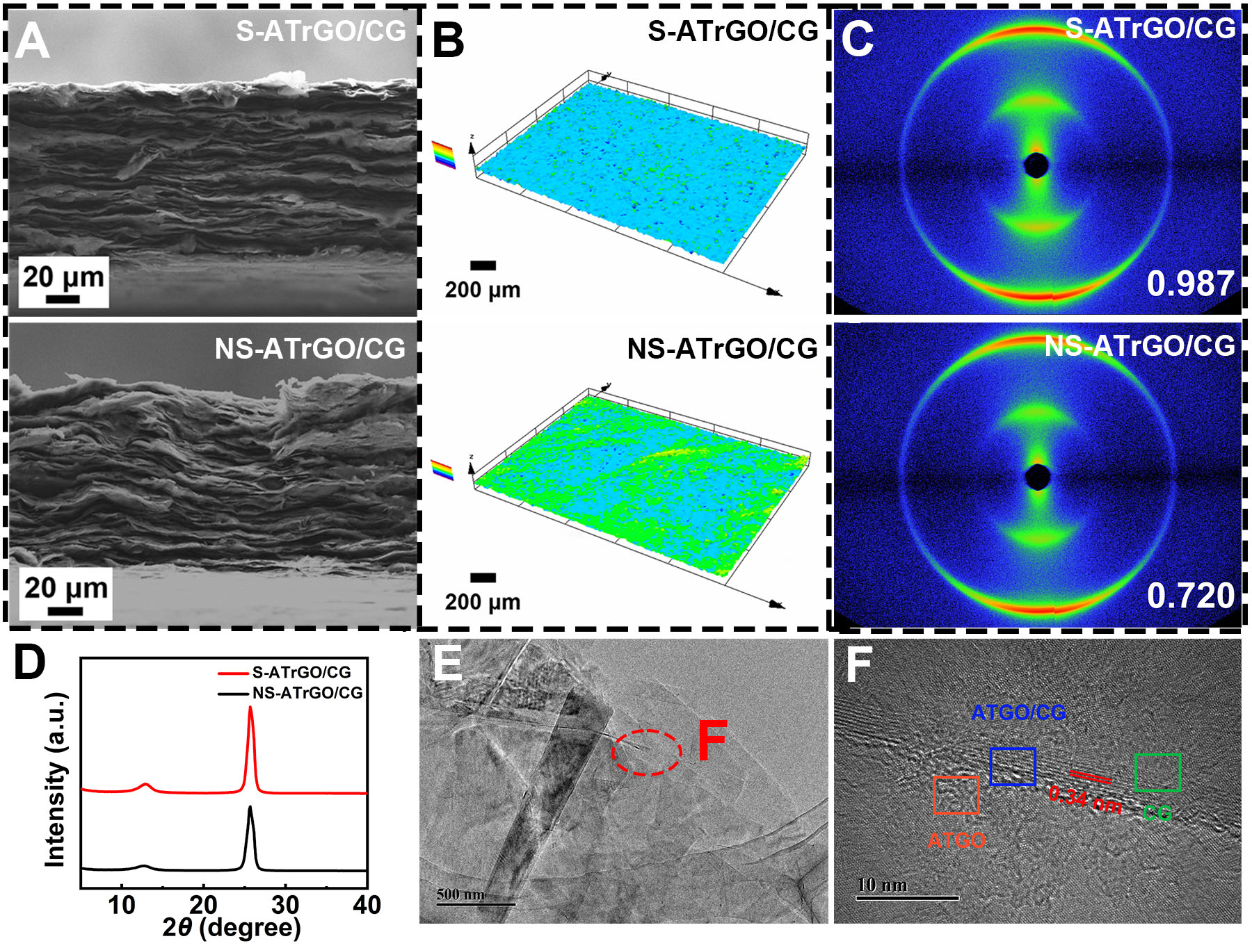
Figure 2. (A) Cross-sectional SEM images of S-ATrGO/CG and NS-ATrGO/CG; (B) Laser scanning confocal microscopy images of
In order to clarify the effectiveness of enhanced orientation order via a capillary slit, WAXS was conducted on S-ATrGO/CG and NS-ATrGO/CG, and the results are shown in Figure 2C. The image presents a crescent-shaped scattering arc that originated from the crystal plane scattering of rGO and CG flakes. This particular signal is a result of microcrystalline scattering of the tight stacking of rGO and CG flakes. The two layers of scattering arcs can be identified as hexagonal crystal systems, representing the (100) and (110) crystal planes of the flakes[47]. In contrast, despite displaying a similar crescent-shaped arc, the scattering pattern of the NS-ATrGO/CG film exhibits a comparatively lower spot intensity than that of the
To further explain the interaction between ATGO and CG, transmission electron microscopy (TEM) characterization was performed on S-ATGO/CG. As shown in Figure 2E, ATGO and CG form a layered stacking structure, with CG attached to the surface of ATGO. Figure 2F shows the high-resolution TEM (HRTEM) image of S-ATGO/CG, in which three typical states are observed in different regions. Due to the presence of numerous functional groups and defects in ATGO, which disrupt the lattice structure, the electron diffraction pattern exhibits ring-shaped diffraction spots [Supplementary Figure 2A]. CG exhibits regular hexagonal symmetric diffraction spots, characteristic of graphite [Supplementary Figure 2B]. In the region where ATGO and CG combine, the diffraction spots of CG overlap with the diffraction rings of ATGO [Supplementary Figure 2C]. This suggests that ATGO and CG can interact and bind together through π-π stacking effects and electrostatic attraction. Calculations using Fourier transformation via Digital Micrograph reveal that the interlayer spacing of the layered CG is 0.34 nm, which is consistent with the typical interlayer spacing of graphene. The interlayer spacing of ATGO is 0.64 nm, corresponding to the average interlayer spacing of GO. These results indicate that CG has successfully combined with ATGO with the help of slit microflows and oxygen functional groups.
The effect of sulfuric acid treatment was confirmed by FTIR spectroscopy and XPS. Supplementary Figure 3 shows the FTIR spectra of GO and ATGO. The infrared (IR) peak at 3,446 cm-1 corresponds to the stretching frequency of the O-H bond, attributed to water vapor in the environment and crystallized water in KBr. The peak at 1,739 cm-1 corresponds to C=O vibration, 1,409 cm-1 to C-O-H vibration and 1,066 cm-1 to C-O-C vibration. Compared to GO, ATGO shows stronger C-O-H vibration and weaker C-O-C vibration, indicating that some epoxy groups have been converted to hydroxyl groups; more active functional groups are beneficial for enhancing electrochemical performance.
XPS was adopted to quantitatively analyze the oxygen-containing functional groups of the samples. The survey spectra of GO and ATGO revealed that their C/O ratios were comparable [Supplementary Figure 4A and B], indicating that treatment with sulfuric acid does not drastically alter the C/O stoichiometry. Moreover, Figure 3A is the C 1s spectrum of GO, which can be deconvolved into five peaks centered at 284.80 eV (C-C/C=C), 286.86 eV (C-OH), 287.30 eV (C-O-C), 288.77 eV (C=O), and 290.39 eV (O-C=O), respectively. Analogously, five peaks centered at 284.80 eV (C-C/C=C), 286.65 eV (C-OH), 287.10 eV
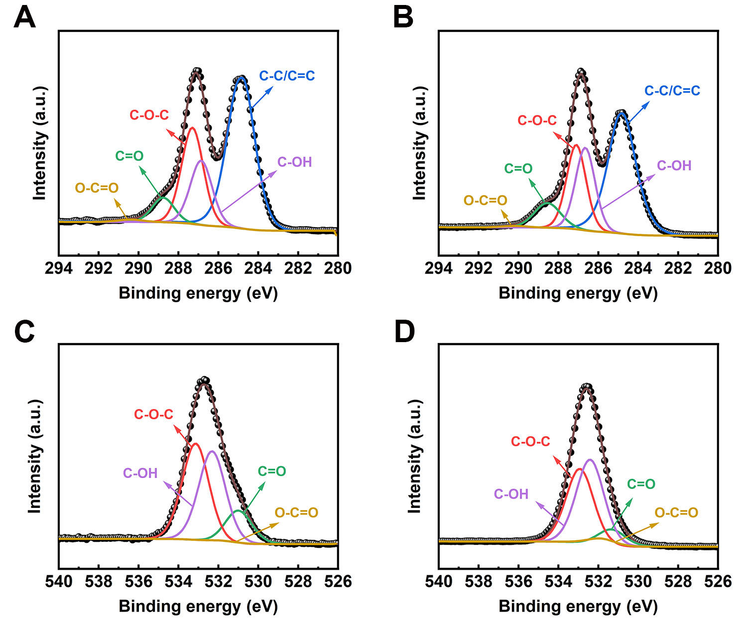
Figure 3. (A) XPS C 1s spectra of GO; (B) XPS C 1s spectra of ATGO; (C) XPS O 1s spectra of GO; (D) XPS O 1s spectra of ATGO. XPS: X-ray photoelectron spectroscopy; ATGO: acid-treated graphene oxide; GO: graphene oxide.
Chemical atomic composition obtained through XPS scan on GO, ATGO and S-ATrGO/CG
| C/O | sp2 C | C-O-C | C-OH | O-C=O | C=O | |
| GO | 2.03 | 51.11% | 25.04% | 16.74% | 0.68% | 6.43% |
| ATGO | 2.24 | 47.31% | 22.02% | 21.54% | 0.46% | 8.67% |
| S-ATrGO/CG | 5.35 | 71.17% | 4.63% | 13.97% | 4.12% | 6.38% |
The S-ATGO/CG and S-ATrGO/CG samples were also analyzed by XPS. After thermal reduction, the intensity of the O 1s peak decreased, and the C/O ratio increased from 2.07 to 5.35 [Supplementary Figure 4C and D]. This noteworthy change can be ascribed to the elimination of oxygen-containing functional groups through pyrolysis[48,49]. The XPS C 1s spectrum of S-ATGO/CG can be deconvolved into five peaks centered at 284.80 eV (C-C/C=C), 286.65 eV (C-OH), 287.10 eV (C-O-C), 288.45 eV (C=O), and 289.37 eV (O-C=O) [Figure 4A]. The XPS C 1s spectrum of S-ATrGO/CG can be deconvolved into five peaks centered at 284.80 eV (C-C/C=C), 286.35 eV (C-OH), 287.12 eV (C-O-C), 288.86 eV (C=O), and 291.45 eV (O-C=O) as shown in Figure 4B. The O 1s spectrum of S-ATGO/CG and S-ATrGO/CG can be deconvolved into the same four peaks centered at 531.22 eV (C=O), 531.89 eV (O-C=O), 532.71 eV (C-OH), and 533.25 eV
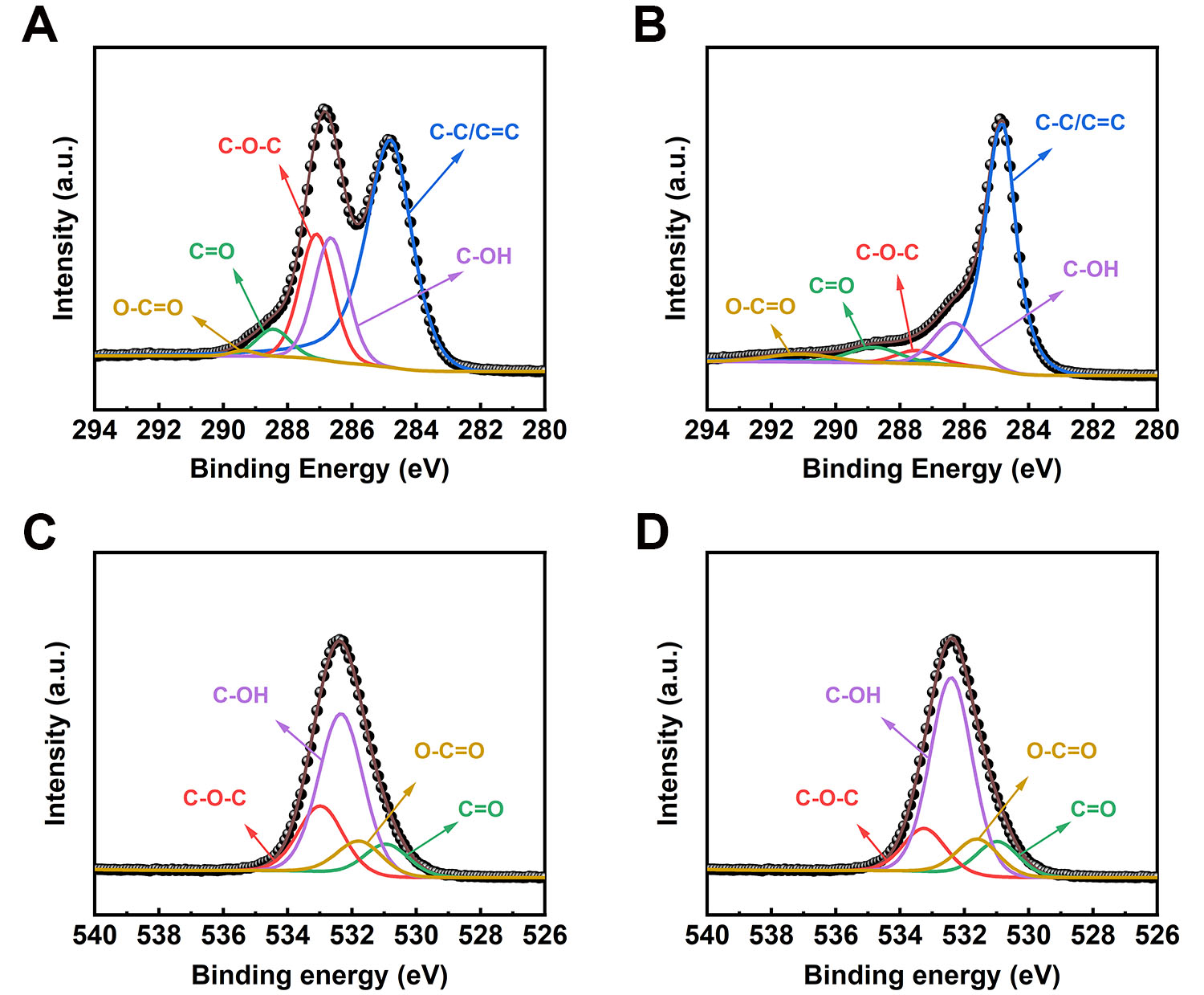
Figure 4. (A) XPS C 1s spectra of S-ATGO/CG; (B) XPS C 1s spectra of S-ATrGO/CG; (C) XPS O 1s spectra of S-ATGO/CG; (D) XPS O 1s spectra of S-ATrGO/CG. XPS: X-ray photoelectron spectroscopy; CG: commercial graphene; ATGO: acid-treated graphene oxide; S-ATrGO: sulfuric acid-treated reduced graphene oxide; NS: non-slit.
To investigate the effect of sulfuric acid ring-opening pretreatment on electrochemical performance, electrochemical tests were conducted on S-OrGO/CG and compared with S-ATrGO/CG. Cyclic voltammetry (CV) curves at scan rates ranging from 5 mV s-1 to 25 mV s-1 are shown in Supplementary Figure 6A and B. A distinct feature is the well-defined redox peaks observed within a similar potential range, indicating that the unreduced oxygen-containing groups on ATGO and original GO contribute to redox reactions and pseudocapacitance[51]. Oxygen-containing functional groups, such as hydroxyls and carboxyls, exist on the surface of heat-treated films, undergoing redox reactions during the charge transfer process, thereby generating faradaic capacitance. The presence of these pseudocapacitors further enhances the specific capacitance of the films.
Based on the CV tests, the pseudocapacitance and electric double layer capacitance (EDLC) contributions of ATGO and original GO were further investigated. Specifically, the EDLC originates from the electrostatic adsorption of ions at the electrode/electrolyte interface, which is a non-faradaic process and does not involve charge transfer or chemical reactions. In contrast, pseudocapacitance arises from fast and reversible faradaic reactions occurring at or near the electrode surface, leading to additional charge storage beyond the electric double layer. It should be noted that in practical electrode systems, pseudocapacitive and diffusion-controlled behaviors are often intertwined. The capacitive contribution also includes a portion of diffusion-controlled charge storage, since both processes contribute to the overall faradaic reaction. Therefore, the term “pseudocapacitance” in this work broadly refers to the total faradaic contribution, including both surface redox and diffusion-related processes. The capacitance contributions were calculated using capacitance differentiation analysis based on the CV curves, as shown in Figure 5A and B. At a scan rate of
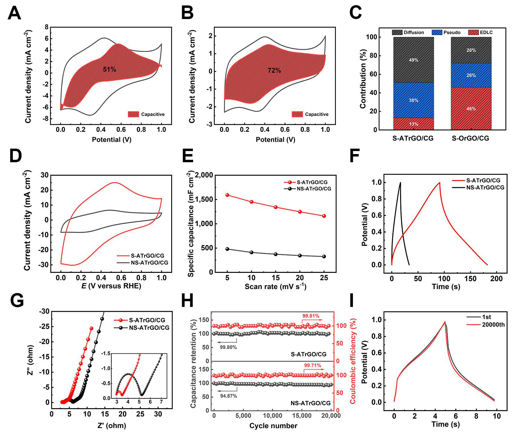
Figure 5. Differentiation of capacitive and diffusion-controlled contribution from CV curves at 5 mV s-1 for (A) S-ATrGO/CG; (B)
The capacitance values of S-OrGO/CG, calculated from the CV curves at different scan rates, are shown in Supplementary Figure 6C. Limited by the ion diffusion rate, the capacitance decreases as the scan rate increases. In the Nyquist plot, the charge transfer resistance of S-OrGO/CG is 42.84 Ω [Supplementary Figure 6D], which is higher than that of S-ATrGO/CG as described below. This is because the untreated GO contains a high content of epoxy groups, which cannot undergo ring-opening to form hydroxyl groups. These epoxy groups cannot be removed during thermal annealing at 350 °C, resulting in incomplete restoration of the sp2 network and inferior electrochemical performance. The galvanostatic charge-discharge (GCD) curve of S-OrGO/CG presents an approximately symmetrical triangular shape [Supplementary Figure 6E], indicating that only a small number of active functional groups participate in the redox reactions. These results confirm that the sulfuric acid ring-opening treatment of ATGO can convert more inert functional groups (epoxy groups) into active functional groups (hydroxyl groups). The cycling stability of
To further emphasize the role of the regular layered structure, prepared by the slit evaporation self-assembly method, in enhancing the capacitance, the electrochemical performance of NS-ATrGO/CG was also evaluated under the same conditions for comparison. The CV curves of both film electrodes were obtained at a scan rate of 25 mV s-1 [Figure 5D]. It can be observed that the current density range of S-ATrGO/CG is much larger than that of NS-ATrGO/CG, accompanied by an increased peak current. This indicates that the regular layered arrangement of the S-ATrGO/CG creates optimal conditions for the transport of electrolyte ions, thereby accelerating the ion transport rate and enabling a fast current response[53]. The CV curves of the NS-ATrGO/CG film electrode were recorded at scan rates ranging from 5 mV s-1 to 25 mV s-1, within the potential window of 0-1 V [Supplementary Figure 6G]. The areal capacitance values were calculated by analyzing the charge derived from the current response in the CV curve at a scan rate of 5 mV s-1. As shown in Figure 5E, S-ATrGO/CG exhibits an areal capacitance of 1,589.78 mF cm-2, significantly higher than that of NS-ATrGO/CG, which measures 480.78 mF cm-2. For volumetric capacitance, the same trend is observed. The volumetric capacitance of S-ATrGO/CG reaches 132.48 F cm-3, which is significantly higher than that of NS-ATrGO/CG at 40.07 F cm-3. As the scan rate increases, the areal capacitance values of both samples decrease to varying degrees. To further evaluate the electrochemical performance of the electrode, CV tests were conducted on S-ATrGO/CG at higher scan rates (5 mV s-1 to 500 mV s-1). The results revealed that when the scan rate exceeded 200 mV s-1, both the anodic and cathodic peaks nearly disappeared [Supplementary Figure 7A]. As shown by the areal capacitance values derived from the CV curves at different scan rates, the areal capacitance decreased from 1,589.78 mF cm-2 to 214.64 mF cm-2 as the scan rate increased from 5 mV s-1 to 500 mV s-1, retaining about 13.5% of its initial value [Supplementary Figure 7B]. This decline is mainly attributed to the insufficient diffusion of electrolyte ions at high scan rates, which hinders the occurrence of surface redox reactions and consequently leads to a reduced capacitance. The capacitance contribution of S-ATrGO/CG at different scan rates is shown in Supplementary Figure 8. As the scan rate increases, the pseudocapacitance provided by ion diffusion gradually decreases.
Figure 5F illustrates the GCD curves of the two samples at a current density of 5 mA cm-2. The single charge-discharge cycle time for S-ATrGO/CG is 183 s, significantly better than the 33 s observed for NS-ATrGO/CG. GCD tests were also performed on S-ATrGO/CG at higher current densities (5 mA cm-2 to
Furthermore, long-term cycling stability is evaluated by subjecting the two samples to 20,000 cycles at a current density of 50 mA cm-2 [Figure 5H]. S-ATrGO/CG shows excellent cycling stability (99.80%) compared to that of NS-rGO/-CG (94.87%). Figure 5I shows the charge-discharge curves of the first and 20,000th cycles from the cycling stability test of S-ATrGO/CG. The curves exhibit no significant changes, and the single charge-discharge cycle time remains consistent, indicating excellent cycling stability of
Comparison of graphene supercapacitor electrodes with recently reported studies
| Materials | Method | Areal specific capacitance | Capacitance retention (cycles) | Ref. |
| S-ATrGO/CG film | Capillary slit-induced self-assembly | 1,589.78 | 99.80% (20,000) | This work |
| rGO/GO | Heating pattern on GO film | 94.8 | 57.1% (20,000) | [2] |
| Functionalized graphene hydrogel | Electrolytic deposition | 400 | 100% (10,000) | [4] |
| Graphene paper | Coating method | 44 | 95.21% (10,000) | [14] |
| GO/rGO film | Blade-casting thermal reduction | 24.8 | 55.8% (4,500) | [41] |
| Activated graphene compact film | Repeated filtration | 89.5 | NA | [56] |
| 3D graphene/graphite paper | Chemical vapor deposition | 15.5 | 112% (10,000) | [57] |
| GO hydrogel | Blade-casting | 71 | 98.3% (5,000) | [58] |
The electrochemical behavior of S-ATrGO/CG film was thoroughly investigated via a series of electrochemical tests. The ATGO here is acting as the conductive additive, flexible backbone, active material, and binder, enhancing the structural integrity of the films and contributing to their overall performance. In order to optimize the loading amount, ATGOs with varying contents of CG were prepared, including 0 wt.%, 30 wt.%, 70 wt.%, 75 wt.%, and 80 wt.%; they were named as S-ATrGO/CG0, S-ATrGO/CG30, S-ATrGO/CG70, S-ATrGO/CG75, and S-ATrGO/CG80, respectively. Their CV curves at a scan rate of 25 mV s-1 are summarized in Figure 6A. Experimental results show that with the addition of CG, the electrochemical active area gradually increases, reaching its maximum value at a content of 75 wt.%. The CV curves of all the samples within the potential range of 0-1 V are shown in Supplementary Figure 11, in which the electrochemical active area also increases linearly with the increased scan rate. The shape of these CV curves remained largely unchanged even with a fivefold increase in the scan rate from 5 mV s-1 to 25 mV s-1, demonstrating the superior reversibility of the samples[60].
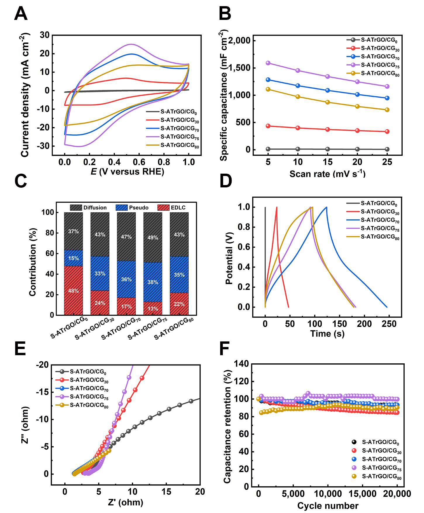
Figure 6. (A) CV curves of S-ATrGO/CG0, S-ATrGO/CG30, S-ATrGO/CG70, S-ATrGO/CG75, and S-ATrGO/CG80 at scan rate of 25 mV s-1; (B) Specific capacitance from CV plots with variation of scan rates; (C) Contributions of capacitive and diffusion-controlled charge storage at various scanning rates; (D) Comparison of GCD curves at a current density of 5 mA cm-2; (E) The Nyquist plots measured in a frequency range between 0.01 and 105 Hz; (F) The specific capacitance retention with 20,000 cycling numbers. CG: commercial graphene; ATGO: acid-treated graphene oxide; S-ATrGO: sulfuric acid-treated reduced graphene oxide; NS: non-slit; GCD: galvanostatic charge-discharge; CV: cyclic voltammetry; GCD: galvanostatic charge-discharge; RHE: reversible hydrogen electrode.
The variation of specific capacitance values with the scan rate is illustrated in Figure 6B. It clearly demonstrates that an increase in the scan rate leads to a reduction in specific capacitance. This occurs because, as the scan rate increases, the contribution of faradaic capacitance decreases, while the EDLC-type specific capacitance becomes dominant. Moreover, the areal capacitance of the films varies greatly under different CG loading amounts. For example, at the scan rate of 5 mV s-1, when 30 wt.% of CG was added, the areal capacitance value increased significantly from 12.54 mF cm-2 for S-ATrGO/CG0 to 436.24 mF cm-2 for S-ATrGO/CG30. The areal capacitance reached its maximum value of 1,589.78 mF cm-2 at 75 wt.%. When the CG loading was further increased to 80 wt.%, the electrochemical performance decreased. This decline can be attributed to the agglomeration of an excessive amount of CG in the film.
As shown in Supplementary Figure 12, the capacitance differentiation analysis of CV curves for samples with different CG loading amounts was performed at the same scan rate (5 mV s-1). The results indicate that all the samples with added CG exhibit a mixed capacitance contribution from both pseudocapacitance and EDLC. The ratio of pseudocapacitance contribution is shown in Figure 6C. It can be observed that as the CG loading amount increases, more graphene nanosheet edges are available for hydroxyl group attachment, thereby providing more pseudocapacitance. When the CG loading reaches 80 wt.%, the number of CG nanosheets exceeds the bonding limit of ATGO, and the remaining unbonded CG nanosheets disrupt the structure of the electrode sheet, leading to a decrease in performance.
The GCD curves of the films with different CG contents at a current density of 5 mA cm-2 are illustrated in Figure 6D. The shape of the discharge curve exhibits distinct characteristics of pseudocapacitance, which is consistent with the results obtained from the CV. The incorporation of CG significantly enhances the charge-discharge cycle time. Figure 6E shows the EIS curves, with the response over a frequency range from 0.01 Hz to 105 Hz. The curve consists of a high-frequency intercept on the real Z axis, a semicircle, and a sloping line in the low-frequency region. This is caused by the pseudocapacitive redox reactions and the double-layer capacitance at the electrode surface[50]. The Rct values for S-ATrGO/CG0, S-ATrGO/CG30,
To further investigate the properties of the S-ATrGO/CG electrode material, SSCs with S-ATrGO/CG//S-ATrGO/CG in a CR2032 coin cell were constructed. Both the positive and negative electrodes maintained consistent area and volume. The CV curves of the SSC at scan rates from 1 mV s-1 to 25 mV s-1 are shown in Figure 7A. It can be observed that after assembly into SSC, the redox peaks are significantly reduced compared to the CV curves of the three-electrode testing system. Even at a scan rate of 1 mV s-1, the redox peaks are not obvious. The areal capacitance performance is also significantly reduced, with a value of
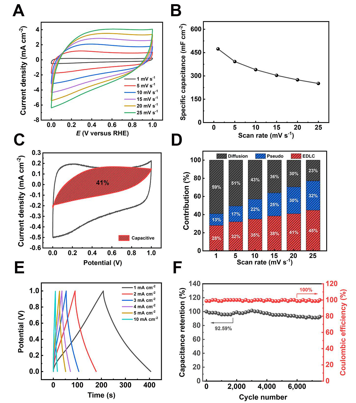
Figure 7. Electrochemical characterization of S-ATrGO/CG//S-ATrGO/CG. (A) CV curves of scan rates ranging from 1 to 25 mV s-1; (B) Specific capacitance from CV plots with variation of scan rates; (C) Differentiation of capacitive and diffusion-controlled contribution from CV curves at 1 mV s-1 for SSC; (D) Contributions of capacitive and diffusion-controlled charge storage at various scanning rates; (E) GCD curves at different current density; (F) The specific capacitance retention and coulombic efficiency of SSC with 7,500 cycling numbers. EDLC: Electric double layer capacitance; CV: cyclic voltammetry; CG: commercial graphene; ATGO: acid-treated graphene oxide; S-ATrGO: sulfuric acid-treated reduced graphene oxide; NS: non-slit; GCD: galvanostatic charge-discharge; SSC: cell symmetric supercapacitor; RHE: reversible hydrogen electrode.
CONCLUSIONS
In summary, by means of a novel slit evaporation self-assembly strategy, this study has successfully fabricated a freestanding S-ATrGO/CG film, which exhibits superior electrochemical properties. The capillary
DECLARATIONS
Authors contributions
Wrote and reviewed the manuscript, made substantial contributions to the conception, performed data acquisition and design of the study, and conducted data analysis and interpretation: Cui, H.; Zhang, J.; Fan, J.
Provided administrative, technical, and material support: Zhang, J.
Availability of data and materials
Morphology and structure for the material characterizations and the electrochemical performance of materials for exploration and comparison are presented in the Supplementary Materials. Further data are available from the corresponding author upon reasonable request.
Financial support and sponsorship
This work was supported by the Dalian High-level Talents Innovation Support Program (2024RY018), the Young Elite Scientists Sponsorship Program by the Chinese Association for Science and Technology (CAST, 2022QNRC001), and the Liaoning Province “Xingliao Talent Plan” (XLYC2002070).
Conflicts of interest
All authors declared that there are no conflicts of interest.
Ethical approval and consent to participate
Not applicable.
Consent for publication
Not applicable.
Copyright
© The Author(s) 2026.
Supplementary Materials
REFERENCES
1. Sheng, L.; Chang, J.; Jiang, L.; et al. Multilayer-folded graphene ribbon film with ultrahigh areal capacitance and high rate performance for compressible supercapacitors. Adv. Funct. Mater. 2018, 28, 1800597.
2. Peng, C.; Li, Q.; Niu, L.; et al. Direct heating pattern on graphene oxide film to build flexible micro-supercapacitors. Carbon 2021, 175, 27-35.
3. Nemala, S. S.; Fernandes, J.; Rodrigues, J.; et al. Sustainable graphene production for solution-processed microsupercapacitors and multipurpose flexible electronics. Nano. Energy. 2024, 127, 109781.
4. Mohamed, N. B.; El-kady, M. F.; Kaner, R. B. Macroporous graphene frameworks for sensing and supercapacitor applications. Adv. Funct. Materials. 2022, 32, 2203101.
5. Lui, C. H.; Liu, L.; Mak, K. F.; Flynn, G. W.; Heinz, T. F. Ultraflat graphene. Nature 2009, 462, 339-41.
7. Novoselov, K. S.; Fal'ko, V. I.; Colombo, L.; Gellert, P. R.; Schwab, M. G.; Kim, K. A roadmap for graphene. Nature 2012, 490, 192-200.
8. Randviir, E. P.; Brownson, D. A.; Banks, C. E. A decade of graphene research: production, applications and outlook. Materials. Today. 2014, 17, 426-32.
9. Xiao, K.; Jiang, X.; Zeng, S.; et al. Porous structure-electrochemical performance relationship of carbonaceous electrode-based zinc ion capacitors. Adv. Funct. Mater. 2024, 34, 2405830.
10. Zhang, J.; Liu, W.; Du, M.; et al. Kinetic investigation of the energy storage process in graphene fiber supercapacitors: unraveling mechanisms, fabrications, property manipulation, and wearable applications. Carbon. Energy. 2025, 7, e625.
11. Bai, C.; Li, S.; Ji, K.; Wang, M.; Kong, D. Stretchable microbatteries and microsupercapacitors for next-generation wearable electronics. Energy. Mater. 2023, 3, 300041.
12. Tan, Y. B.; Lee, J. Graphene for supercapacitor applications. J. Mater. Chem. A. 2013, 1, 14814-43.
13. Liu, Z.; Jiang, L.; Sheng, L.; et al. Oxygen clusters distributed in graphene with “paddy land” structure: ultrahigh capacitance and rate performance for supercapacitors. Adv. Funct. Materials. 2018, 28, 1705258.
14. Fu, Y.; Xu, L.; Tian, W.; Liu, Y.; Cao, D.; Wang, Q. Self-assembly of free-standing surface-oxidized multilayer graphene film for high volumetric supercapacitors. Carbon 2023, 213, 118286.
15. Zhang, H.; Yang, D.; Lau, A.; Ma, T.; Lin, H.; Jia, B. Hybridized graphene for supercapacitors: beyond the limitation of pure graphene. Small 2021, 17, 2007311.
16. Zhang, C. J.; Nicolosi, V. Graphene and MXene-based transparent conductive electrodes and supercapacitors. Energy. Storage. Mater. 2019, 16, 102-25.
17. Ye, X.; Zhou, Q.; Jia, C.; Tang, Z.; Zhu, Y.; Wan, Z. Producing large-area, foldable graphene paper from graphite oxide suspensions by in-situ chemical reduction process. Carbon 2017, 114, 424-34.
18. Yoon, Y.; Lee, K.; Kwon, S.; et al. Vertical alignments of graphene sheets spatially and densely piled for fast ion diffusion in compact supercapacitors. ACS. Nano. 2014, 8, 4580-90.
19. Chen, C.; Huang, J.; Zhang, Q.; et al. Annealing a graphene oxide film to produce a free standing high conductive graphene film. Carbon 2012, 50, 659-67.
20. Lin, Y.; Balizan, E.; Lee, L. A.; Niu, Z.; Wang, Q. Self-assembly of rodlike bio-nanoparticles in capillary tubes. Angew. Chem. Int. Ed. Engl. 2010, 49, 868-72.
21. Torrisi, L.; Cutroneo, M.; Havranek, V.; et al. Self-supporting graphene oxide films preparation and characterization methods. Vacuum 2019, 160, 1-11.
22. Kim, J. E.; Han, T. H.; Lee, S. H.; et al. Graphene oxide liquid crystals. Angew. Chem. Int. Ed. Engl. 2011, 50, 3043-7.
23. Zheng, W.; Liu, J.; Guo, Y.; Han, G.; Yi, Y. Regulation of molecular orientations of A-D-A nonfullerene acceptors for organic photovoltaics: the role of end-group π-π stacking. Adv. Funct. Mater. 2022, 32, 2108551.
24. Tian, J.; Wu, S.; Yin, X.; Wu, W. Novel preparation of hydrophilic graphene/graphene oxide nanosheets for supercapacitor electrode. Appl. Surf. Sci. 2019, 496, 143696.
25. Wu, Z. S.; Parvez, K.; Li, S.; et al. Alternating stacked graphene-conducting polymer compact films with ultrahigh areal and volumetric capacitances for high-energy micro-supercapacitors. Adv. Mater. 2015, 27, 4054-61.
26. Xin, G.; Zhu, W.; Deng, Y.; et al. Microfluidics-enabled orientation and microstructure control of macroscopic graphene fibres. Nat. Nanotechnol. 2019, 14, 168-75.
27. Lee, D.; Seo, J. Layer-by-layer-stacked graphene/graphene-island supercapacitor. AIP. Adv. 2020, 10, 055202.
28. Long, C.; Chen, X.; Jiang, L.; Zhi, L.; Fan, Z. Porous layer-stacking carbon derived from in-built template in biomass for high volumetric performance supercapacitors. Nano. Energy. 2015, 12, 141-51.
29. Arvas, M. B.; Karatepe, N.; Gencten, M.; Sahin, Y. Fabrication of high-performance symmetrical coin cell supercapacitors by using one step and green synthesis sulfur doped graphene powders. New. J. Chem. 2021, 45, 6928-39.
30. Jiang, L.; Sheng, L.; Long, C.; Wei, T.; Fan, Z. Functional pillared graphene frameworks for ultrahigh volumetric performance supercapacitors. Adv. Energy. Mater. 2015, 5, 1500771.
31. Haridas, H.; Kader, A. K. A.; Sellathurai, A.; Barz, D. P. J.; Kontopoulou, M. Noncovalent functionalization of graphene nanoplatelets and their applications in supercapacitors. ACS. Appl. Mater. Interfaces. 2024, 16, 16630-40.
32. Chan, K.; Lin, H.; Qiao, K.; Jia, B.; Lau, K. Multifunctional graphene oxide paper embodied structural dielectric capacitor based on carbon fibre reinforced composites. Compos. Sci. Technol. 2018, 163, 180-90.
33. Sun, M. H.; Huang, S. Z.; Chen, L. H.; et al. Applications of hierarchically structured porous materials from energy storage and conversion, catalysis, photocatalysis, adsorption, separation, and sensing to biomedicine. Chem. Soc. Rev. 2016, 45, 3479-563.
34. Costentin, C.; Savéant, J. M. Energy storage: pseudocapacitance in prospect. Chem. Sci. 2019, 10, 5656-66.
35. Qiu, J.; Wang, D.; Geng, H.; Guo, J.; Qian, S.; Liu, X. How Oxygen-Containing Groups on Graphene Influence the Antibacterial Behaviors. Adv. Mater. Interfaces. 2017, 4, 1700228.
36. Singla, R.; Kottantharayil, A. Stable hydroxyl functionalization and p-type doping of graphene by a non-destructive photo-chemical method. Carbon 2019, 152, 267-73.
37. Russell, J. C.; Posey, V. A.; Gray, J.; et al. High-performance organic pseudocapacitors via molecular contortion. Nat. Mater. 2021, 20, 1136-41.
38. Wu, X.; Yang, D.; Wang, C.; Jiang, Y.; Wei, T.; Fan, Z. Functionalized three-dimensional graphene networks for high performance supercapacitors. Carbon 2015, 92, 26-30.
39. Khine, Y. Y.; Wen, X.; Jin, X.; Foller, T.; Joshi, R. Functional groups in graphene oxide. Phys. Chem. Chem. Phys. 2022, 24, 26337-55.
40. Zhao, X.; Zhou, Y.; Xu, Y.; et al. Customizing oxygen-containing functional groups for reduced graphene oxide film supercapacitor with high volumetric performance. J. Energy. Storage. 2022, 52, 104642.
41. Guo, J.; Wang, R.; Tjiu, W. W.; Pan, J.; Liu, T. Synthesis of Fe nanoparticles@graphene composites for environmental applications. J. Hazard. Mater. 2012, 225-226, 63-73.
42. Reynosa-Martínez, A. C.; Gómez-Chayres, E.; Villaurrutia, R.; López-Honorato, E. Controlled reduction of graphene oxide using sulfuric acid. Materials 2020, 14, 59.
43. Niu, Y.; Zhao, J.; Zhang, X.; et al. Large area orientation films based on graphene oxide self-assembly and low-temperature thermal reduction. Appl. Phys. Lett. 2012, 101, 181903.
44. Li, P.; Yang, M.; Liu, Y.; et al. Continuous crystalline graphene papers with gigapascal strength by intercalation modulated plasticization. Nat. Commun. 2020, 11, 2645.
45. Chen, W.; Xiao, H.; Hou, L.; et al. A flexible composite film electrode and supercapacitor based on combined effect between graphene oxide and graphene. Mater. Sci. Eng. B. 2023, 297, 116724.
46. Yang, Z.; Zhang, J.; Wang, C.; et al. Capillary assisted self-assembly and nascent hydrogen reduction of graphene oxide on Al: Formation of C-O-Al bonds under mild condition. Carbon 2023, 215, 118474.
47. Li, S.; Fan, Z.; Wu, G.; et al. Assembly of nanofluidic MXene fibers with enhanced ionic transport and capacitive charge storage by flake orientation. ACS. Nano. 2021, 15, 7821-32.
48. Singh, M.; Yadav, A.; Kumar, S.; Agarwal, P. Annealing induced electrical conduction and band gap variation in thermally reduced graphene oxide films with different sp2/sp3 fraction. Appl. Surf. Sci. 2015, 326, 236-42.
49. Nia, Z.; Chen, J.; Tang, B.; Yuan, B.; Wang, X.; Li, J. Optimizing the free radical content of graphene oxide by controlling its reduction. Carbon 2017, 116, 703-12.
50. Gao, X.; Jang, J.; Nagase, S. Hydrazine and thermal reduction of graphene oxide: reaction mechanisms, product structures, and reaction design. J. Phys. Chem. C. 2010, 114, 832-42.
51. Lei, Z.; Zhang, J.; Zhang, L. L.; Kumar, N. A.; Zhao, X. S. Functionalization of chemically derived graphene for improving its electrocapacitive energy storage properties. Energy. Environ. Sci. 2016, 9, 1891-930.
52. Pu, X.; Zhao, D.; Fu, C.; et al. Understanding and calibration of charge storage mechanism in cyclic voltammetry curves. Angew. Chem. Int. Ed. 2021, 60, 21310-8.
53. Nagarani, S.; Sasikala, G.; Yuvaraj, M.; Balachandran, S.; Dhilip Kumar, R.; Kumar, M. Cost effective, metal free reduced graphene oxide sheet for high performance electrochemical capacitor application. Mater. Sci. Eng. B. 2022, 284, 115852.
54. Le, V. T.; Ryu, H.; Han, S. A.; et al. Simultaneous enhancement of specific capacitance and potential window of graphene-based electric double-layer capacitors using ferroelectric polymers. J. Power. Sources. 2021, 507, 230268.
55. Sun, X.; Lu, H.; Rufford, T. E.; et al. A flexible graphene-carbon fiber composite electrode with high surface area-normalized capacitance. Sustainable. Energy. Fuels. 2019, 3, 1827-32.
56. Wu, Q.; He, T.; Zhang, Y.; et al. Cyclic stability of supercapacitors: materials, energy storage mechanism, test methods, and device. J. Mater. Chem. A. 2021, 9, 24094-147.
57. Wu, Z.; Yang, S.; Zhang, L.; Wagner, J. B.; Feng, X.; Müllen, K. Binder-free activated graphene compact films for all-solid-state micro-supercapacitors with high areal and volumetric capacitances. Energy. Storage. Mater. 2015, 1, 119-26.
58. Ramadoss, A.; Yoon, K.; Kwak, M.; Kim, S.; Ryu, S.; Jang, J. Fully flexible, lightweight, high performance all-solid-state supercapacitor based on 3-Dimensional-graphene/graphite-paper. J. Power. Sources. 2017, 337, 159-65.
59. Xiong, Z.; Liao, C.; Han, W.; Wang, X. Mechanically tough large-area hierarchical porous graphene films for high-performance flexible supercapacitor applications. Adv. Mater. 2015, 27, 4469-75.
Cite This Article
How to Cite
Download Citation
Export Citation File:
Type of Import
Tips on Downloading Citation
Citation Manager File Format
Type of Import
Direct Import: When the Direct Import option is selected (the default state), a dialogue box will give you the option to Save or Open the downloaded citation data. Choosing Open will either launch your citation manager or give you a choice of applications with which to use the metadata. The Save option saves the file locally for later use.
Indirect Import: When the Indirect Import option is selected, the metadata is displayed and may be copied and pasted as needed.
About This Article
Copyright

Data & Comments
Data
0


Comments
Comments must be written in English. Spam, offensive content, impersonation, and private information will not be permitted. If any comment is reported and identified as inappropriate content by OAE staff, the comment will be removed without notice. If you have any queries or need any help, please contact us at [email protected].