




Frequency-thickness normalized electromagnetic parameter design for broadband electromagnetic wave absorption in FeCoCu alloy foams
 0
0 Abstract
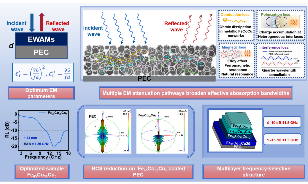
Electromagnetic wave absorbing materials (EWAMs) are critical for mitigating electromagnetic (EM) pollution, yet achieving broadband absorption with thin coatings remains challenging because clear criteria for EM parameters optimization are still lacking. Herein, a frequency-thickness normalized EM parameters construction strategy is proposed based on transmission line theory. By quantitatively correlating complex permittivity, frequency, and coating thickness with reflection-loss minimization, the optimal complex permittivity for thin broadband absorption is constructed as
Keywords
INTRODUCTION
The rapid proliferation of electronic devices and wireless communication systems has led to an increasingly complex electromagnetic (EM) environment, raising growing concerns regarding EM pollution[1-3]. EM wave absorbing materials (EWAMs) are therefore widely regarded as an effective solution for suppressing unwanted EM radiation and ensuring the reliable operation of electronic systems[4-6]. Ideal EWAMs are generally expected to exhibit strong EM absorption intensity, broad effective absorption bandwidth (EAB) with thin coating thickness to meet the demands of device miniaturization and integration[7,8]. A wide variety of material systems, including carbon-based EWAMs, graphene-based polymer composites with segregated conductive networks, magnetic metals/alloys, ceramics and their hybrid composites, have been reported as promising EWAMs with broadband absorption[9-12]. However, despite decades of intensive research, achieving broadband EM wave absorption with thin coatings remains a fundamental and unresolved challenge.
With a given coating thickness, achieving effective EM absorption requires the EM parameters of EWAMs to satisfy a specific relationship at different frequencies, which imposes an intrinsic constraint on broadband EM absorption with thin coating thicknesses. From a mechanistic perspective, EM wave absorption can be commonly attributed to conduction loss, polarization loss, and magnetic loss[13]. Many studies have demonstrated that introducing multiple EM loss mechanisms can effectively broaden the EAB[14,15]. Accordingly, numerous strategies have been proposed to enhance one or more of these loss mechanisms, such as increasing electrical conductivity, constructing heterogeneous interfaces, introducing dipolar defects, or incorporating magnetic components[16,17]. For instance, Liu et al. ingeniously fabricated ZnO/NiO/N-doped carbon/CNT composites through microwave non-equilibrium pyrolysis of Zn-Ni bimetallic MOF/CNT precursors[18]. The CNT scaffold with strong microwave-coupling capability induces plasma arc discharge and transient thermal shock, promoting the confined nucleation and nanoscale dispersion of ZnO/NiO within the carbon matrix. The abundant ZnO/NiO/carbon heterointerfaces generate pronounced interfacial polarization, while N-doped carbon and CNTs contribute dipolar polarization and moderate conduction loss. Benefiting from these synergistic dielectric loss mechanisms and improved impedance matching, the optimized BMO-carbon/CNT-2 composite achieves a minimum reflection loss of -55.16 dB at 1.85 mm and an EAB of 4.64 GHz[18]. However, merely increasing the number of loss mechanisms through compositional regulation and microstructural design does not necessarily lead to a further expansion of EAB. This is because the reflection loss (RL) values of an EWAM are determined by both the impedance matching characteristics at the air-EWAM interface and the intrinsic EM attenuation capability within the EWAM[19,20]. Effective impedance matching requires the magnetic loss capacity to be comparable to dielectric loss. However, in dielectric-loss-dominated systems, the magnetic loss introduced by incorporating magnetic components is often negligible[21,22]. Consequently, satisfactory impedance matching can only be achieved within a relatively narrow frequency range.
The EAB and coating thickness of EWAMs are fundamentally constrained by the Planck-Rozanov limit (
Based on the above considerations, transmission line theory was first employed to establish the functional relationship among relative permittivity, coating thickness, and frequency required for achieving optimal EM absorption. It was also demonstrated that single conduction loss mechanism is insufficient to realize broadband absorption, whereas the incorporation of additional polarization and magnetic loss mechanisms can effectively relax this constraint and broaden the achievable bandwidth. Inspired by these findings, FeCo foams are initially fabricated via an auto-combustion process followed by H₂ reduction, and different amounts of Cu were subsequently introduced. The incorporation of Cu not only enables regulation of conduction loss but also promotes interfacial polarization due to the coexistence of BCC and FCC crystalline phases. Benefiting from the strong magnetic loss capability of the FeCo alloy, the enhanced conductive and interfacial polarization losses induced by Cu addition, and the formation of conductive networks facilitated by the foam-like architecture, the composition-optimized FeCoCu foam (Fe65Co30Cu5 foam) exhibits pronounced broadband EM absorption performance. Notably, an EAB of 7.36 GHz is achieved with coating thickness only 1.74 mm. This work not only demonstrates a broadband EWAM but also establishes a physically grounded design framework for the rational development of thin, broadband EWAMs.
EXPERIMENTAL
Synthesis of FeCo foam and FeCoCu foam
FeCo alloy foam was fabricated through a sol-gel auto-combustion process followed by hydrogen reduction. Briefly, 3.030 g (7.5 mmol) of Fe(NO3)3·9H2O, 0.728 g (2.5 mmol) of Co(NO3)2·6H2O, and 1.239 g (16.5 mmol) of glycine were dissolved in 100 mL of deionized water under magnetic stirring at 600 r min-1 and room temperature for 30 min to obtain a homogeneous precursor solution. The solution was subsequently heated to 220 °C to remove excess water, during which self-sustained combustion was triggered. The resulting oxide precursor was then reduced at 550 °C for 6 h in a 5% H2/95% Ar atmosphere with a heating rate of 3 °C min-1, yielding the FeCo alloy foam.
FeCoCu alloy foams with varying Cu contents were prepared using an identical synthetic protocol. Specifically, 5 at.%, 10 at.%, and 20 at.% of Fe were nominally substituted by Cu in the precursor formulation. The obtained samples were denoted as Fe65Co30Cu5 foam, Fe60Co30Cu10 foam, and Fe50Co30Cu20 foam, respectively, according to the nominal atomic feeding ratios of Fe, Co, and Cu in the precursor solutions. It should be noted that these sample names represent nominal atomic ratios rather than the directly measured elemental compositions.
Characterization
Scanning electron microscopy (SEM) images were collected using a Phenom scanning electron microscope operated at an accelerating voltage of 15 kV, and the samples were sputter-coated with gold before observation. TEM observations and elemental mapping were performed on a Tecnai F20 transmission electron microscope operated at 300 kV. The transmission electron microscopy (TEM) samples were prepared by dispersing the powders in anhydrous ethanol under ultrasonication for 30 min. Powder X-ray diffraction (XRD) patterns were recorded on a Rigaku D/MAXRC diffractometer equipped with Cu Kα radiation (λ = 1.5406 Å), operated at 40.0 kV and 40.0 mA, with a 2θ scanning range of 10-90°. Magnetic hysteresis loops were measured using a vibrating sample magnetometer (VSM, LakeShore, Model 7,404 series) at room temperature. Inductively coupled plasma atomic emission spectroscopy (ICP-AES) was carried out using an Optima 8300 instrument (PerkinElmer, USA), and the samples were dissolved using aqua regia before measurement. Mercury intrusion porosimetry was performed using a Micromeritics AutoPore IV 9520 instrument.
For EM parameter measurements, the as-prepared FeCoCu foam powders were mixed with paraffin at a mass ratio of 60:40. Before mixing, paraffin was melted at 60 °C, and the powders were thoroughly mixed by manual grinding for 15 min to obtain a homogeneous composite. The mixture was then loaded into a standard coaxial mold and pressed into toroidal specimens under a pressure of 1.0 MPa for 1.0 min. The obtained specimens had an outer diameter of 7.00 mm, and an inner diameter of 3.04 mm. The sample surfaces were kept flat and compact to ensure good contact with the coaxial fixture. The complex permittivity and permeability were measured using an Agilent N5234A vector network analyzer in the frequency range of 2.00-18.00 GHz with a frequency step of 0.08 GHz. Samples from different preparation batches were measured three times to evaluate repeatability. Owing to the sensitivity of foam-like alloys to specimen preparation, slight variations in the EM parameters and calculated EM absorption performance can be observed, but consistent EM wave absorption behavior was obtained across different batches.
Theoretical calculation and CST simulation
To establish the quantitative relationship between EM parameters, thickness, and frequency for optimal absorption, the reflection loss (RL) was calculated based on classical transmission line theory. The RL values are expressed as[30-34]:
where Zin is the normalized input impedance, c is the velocity of EM wave in vacuum, and d is the coating thickness of EWAMs. The frequency was varied from 6.00 to 18.00 GHz (step: 0.01 GHz), and the thickness ranged from 1.00 to 3.00 mm (step: 0.25 mm).
For each fixed combination of f and d, μr was set to 1.00-0.00j to isolate the dielectric contribution and establish a reference permittivity-frequency-thickness relationship for RL minimization. This assumption is mainly applicable to nonmagnetic or weakly magnetic EWAMs and does not exclude the contribution of magnetic loss; for magnetic EWAMs, permeability provides additional degrees of freedom for impedance regulation and bandwidth broadening, as discussed below. The real (εr') and imaginary parts (εr'') of permittivity were scanned over a wide range of 0-200 with a step size of 0.10, and the corresponding values yielding the minimum RL were extracted. This range was selected to cover a broad dielectric parameter space from weakly lossy dielectric materials to highly conductive or strongly dielectric-loss-dominated EWAMs, and it is sufficiently wider than the typical permittivity range of most practical EWAMs in the GHz region. The step size of 0.10 provides a balance between numerical resolution and computational efficiency, because the calculated RL varies continuously with εr′ and εr″. During the extraction process, the optimal permittivity values were located inside the selected scanning domain rather than at the upper boundary, indicating that the range of 0-200 was adequate for identifying the RL-minimized parameters.
To evaluate the intrinsic bandwidth limitation of pure conduction loss, the free electron model was adopted. In this case, εr' was treated as a frequency-independent constant (εr' = k), which represents the real permittivity in the conduction-loss model, while εr'' follows[35,36]:
where σ is the electrical conductivity and ε0 is the vacuum permittivity. The parameter k was varied from 3.00 to 18.00 (step: 3.00), and σ ranged from 0.00 to 6.00 S m-1 (step: 0.01 S m-1).
For polarization-dominated loss, the Debye relaxation model was employed to determine the maximum achievable bandwidth under a single relaxation process[37,38]:
where σ, ε∞, εs and τ refer to the electrical conductivity, the dielectric permittivity at high-frequency limit, the static permittivity and the relaxation time, respectively. The parameter ε∞ was varied from 0.00 to 10.00 (step: 0.10), εs-ε∞ ranged from 0.00 to 20.00 (step: 0.10), and 1/τ was scanned within 5.0 × 10¹⁰ s-1 -20.0 × 10¹⁰ s-1 (step: 1.0 × 10⁹ s-1).
All EM simulations were conducted using CST Microwave Studio 2019. For radar cross-section (RCS) simulations, a square perfect electric conductor (PEC) plate (thickness: 1.0 mm, side length: 180 mm) was coated with a 1.75 mm EM absorbing layer (Fe70Co30, Fe65Co30Cu5, Fe60Co30Cu10, and Fe50Co30Cu20 foam, respectively). The simulation frequency ranged from 2.00 to 18.00 GHz (step: 0.08 GHz). Open boundary conditions were applied in all directions, and a plane wave was incident along the -z direction. For angular-dependent RCS evaluation, the frequency was fixed at 9.20 GHz, and the incident angle was scanned from -90° to 90° (step: 1°), with other parameters unchanged. The EM absorption performance of the multilayer periodic structure was simulated under similar conditions, except that a waveguide port excitation (Port 1 along -z) was used. The structure consisted of a PEC backing layer (1.0 mm) and four EM absorbing layers (each 1.5 mm thick), with lateral dimensions of 6.0, 7.0, 8.0, and 10.0 mm from top to bottom. The corresponding EWAMs were Fe70Co30, Fe65Co30Cu5, Fe60Co30Cu10, and Fe50Co30Cu20 foam, respectively. Due to the presence of the PEC backing, all incident EM waves are reflected, and thus the EM absorption performance can be directly evaluated from the reflection coefficient[2]:
RESULTS AND DISCUSSION
Theoretical construction optimized EM parameters
Achieving broadband EM wave absorption with a single-layer homogeneous EWAM backed by a metal plate with a relatively small coating thickness (≤ 2.0 mm) remains a critical challenge. Conventional strategies primarily rely on empirical optimization of composition and microstructure, lacking direct theoretical guidance. In practical design, the EM wave absorption performance is typically evaluated by applying transmission line theory to the measured complex permittivity and permeability, which inherently leads to an empirical correlation between frequency-dependent EM parameters and EABs. However, if the functional relationship between the optimal EM parameters and the thickness-frequency combination can be established, EWAMs design can be rationally guided by tuning the EM parameters toward this target relationship, which is of great significance for the development of broadband EWAMs. The RL values of EWAMs are governed by the εr and μr [Equations (1) and (2)]. For simplification, the magnetic contribution was neglected (μr = 1.00-0.00j), allowing the determination of the required εr' and εr'' that minimize RL values at given coating thicknesses and frequencies. As shown in Figure 1A and B, the extracted permittivity distributions lead to RL values below -40.00 dB across multiple thicknesses (1.50, 1.75, and 2.00 mm), indicating nearly ideal EM absorption performance [Figure 1C]. To gain further insight into the governing mechanism, two characteristic parameters were introduced, defined as:
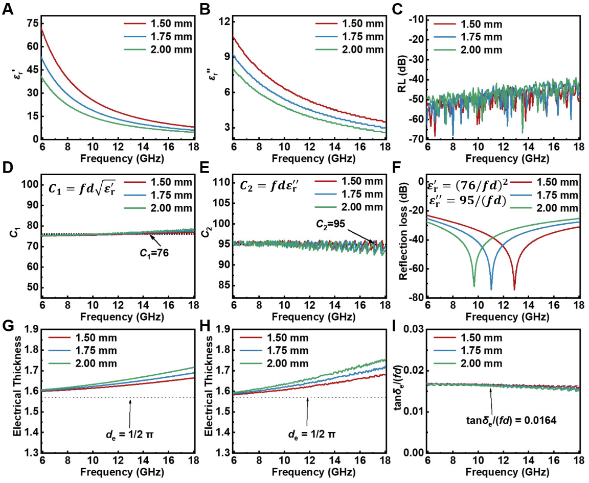
Figure 1. Theoretical determination of optimal permittivity for broadband EM wave absorption based on transmission line theory. (A) εr', and (B) εr'' as a function of frequency with different coating thicknesses (1.50, 1.75, and 2.00 mm); (C) Corresponding RL values calculated using the extracted permittivity. Frequency dependence of the parameter (D) C1, and (E) C2; (F) Simulated RL values using the constructed optimal permittivity; (G) Electrical thickness calculated from the constructed permittivity defined by Equations (9) and (10). (H) Electrical thickness, and (I) normalized dielectric loss factor recalculated from the RL-minimized permittivity extracted at each frequency-thickness point. EM: Electromagnetic; RL: reflection loss.
Remarkably, both C1 and C2 remain nearly constant with respect to frequency [Figure 1D and E], with values of approximately 76 and 95, respectively. This observation suggests that the optimal permittivity follows the relationships:
Under this condition, excellent EM absorption performance is expected over a wide frequency range.
To validate this hypothesis, the permittivity was constrained to satisfy the above relations at 1.50, 1.75, and 2.00 mm, with (μr' = 1.00) and (μr'' = 0.00). The calculated RL values remain below -20.00 dB across the entire frequency range, confirming the robustness of the proposed relationship [Figure 1F]. Furthermore, the universality of this model was examined by extending the thickness to 1.00-3.00 mm (step: 0.25 mm). The corresponding permittivity distributions [Supplementary Figure 1A and B] and RL curves [Supplementary Figure 1C] demonstrate consistently strong absorption, indicating that the proposed functional form provides a reliable guideline for broadband absorber design.
To further clarify the physical meaning of C1 and C2, the effective electrical thickness and normalized dielectric loss factor were analyzed. The constants C1 and C2 are not merely numerical fitting parameters, but reflect the phase-matching and attenuation requirements of the EWAM. For the optimized relationship εr′ ≈ (C1/fd)2, C1 directly determines the electrical thickness. When f is expressed in GHz and d in mm, the value of c/4 is approximately 75, which is very close to the extracted C1 value of approximately 76. This indicates that the εr′ scaling governed by C1 maintains the EWAM close to the quarter-wavelength phase-cancellation condition over different frequency-thickness combinations. In comparison, C2 controls the εr" required for energy dissipation. The ratio C2/C12 is approximately 0.0164, corresponding to the normalized tanδe, and gives tanδe ≈ (C2/C12) fd. Therefore, the tanδe increases with fd, providing stronger EM attenuation at higher frequencies or larger thicknesses to suppress residual reflection. From this viewpoint, C1 mainly reflects the phase/electrical-thickness requirement, whereas C2 reflects the normalized attenuation requirement. Their combination enables simultaneous regulation of quarter-wavelength cancellation, impedance matching, and internal EM attenuation. The effective electrical thickness was analyzed using[39]:
Figure 1G shows the electrical thickness calculated from the constructed permittivity defined by Equations (9) and (10), whereas Figure 1H shows the electrical thickness recalculated from the RL-minimized permittivity extracted at each frequency-thickness point. The consistency between these two results confirms that the constructed parameter relationship captures the near-quarter-wavelength condition required for optimal absorption. As shown in Figure 1G, the electrical thickness remains nearly constant and is centered around
which increases linearly with the product of f and d. This implies that at higher frequencies or larger thicknesses, the dielectric loss is automatically enhanced, ensuring sufficient attenuation to suppress multiple reflections from the metallic backing. Essentially, the proposed functional form realizes a normalization of frequency and thickness, allowing both impedance matching and attenuation to approach optimal conditions simultaneously over a broad parameter space. Further calculations reveal that the electrical thickness corresponding to optimal absorption remains consistently close to
Bandwidth limitation of single loss mechanism
Although the optimal permittivity required for broadband absorption has been theoretically established, it remains highly challenging to realize such a functional relationship through practical material design. This difficulty arises from the fact that the frequency-dependent permittivity is fundamentally governed by intrinsic loss mechanisms, which can generally be classified into conduction loss and polarization loss[41,42]. Importantly, the frequency dependence associated with these mechanisms is inherently fixed and deviates from the idealized permittivity-frequency relationship derived above. For conduction-dominated EWAMs, the dielectric response originates from leakage currents and can be equivalently described by an ideal capacitor in parallel with a resistor. In this case, the real part of permittivity remains constant, determined by the charge storage capability, while the imaginary part follows an inverse frequency dependence governed by the electrical conductivity [Equation (3)]. Here, k denotes the frequency-independent εr' in the pure conduction-loss model, and is used together with electrical conductivity to evaluate the bandwidth limitation of conduction-dominated EWAMs. The EABs as a function of permittivity and conductivity with coating thicknesses of 1.50, 1.75, and 2.00 mm are presented in Figure 2A-C. It is evident that, regardless of increasing the permittivity or conductivity, the effective bandwidth exhibits a clear upper limit. Although increasing coating thickness can extend this limit, the maximum EAB remains below 5.0 GHz with a coating thickness of 2.0 mm. This indicates that conduction loss alone is insufficient to achieve broadband absorption under thin-layer conditions.
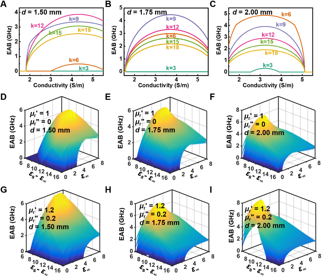
Figure 2. EAB maps of conduction-loss-dominated EWAMs as functions of electrical conductivity σ and the constant real permittivity k (εr' = k) with coating thicknesses of (A) 1.50, (B) 1.75, and (C) 2.00 mm, respectively. Three-dimensional maps of EABs as a function of ε∞, εs-ε∞, and τ for polarization-loss-dominated materials with coating thicknesses of (D) 1.50, (E) 1.75, and (F) 2.00 mm, respectively. Corresponding EAB distributions after introducing magnetic loss (μr' =1.2 and μr" = 0.2) with coating thicknesses of (G) 1.50, (H) 1.75, and (I) 2.00 mm, respectively. EAB: Effective absorption bandwidth; EWAM: electromagnetic wave absorbing material.
When the dielectric response is dominated by polarization loss, the permittivity can be described by the Debye relaxation model [Equations (4) and (5)], where ε∞, εs-ε∞, and τ represent the high-frequency permittivity limit, relaxation strength, and relaxation time, respectively. The corresponding EABs under different parameter combinations are shown in Figure 2D-F. For thicknesses of 1.50, 1.75, and 2.00 mm, the maximum EABs are 5.25, 5.97, and 6.60 GHz, respectively, achieved at (ε∞, εs-ε∞, τ) = (5.8, 11.2, 10.8 ps), (4.2, 10.3 ,12.2 ps), and (3.1, 9.5, 12.8 ps). These results clearly demonstrate that polarization loss, owing to its additional tunable parameters, provides a higher upper limit of EABs compared to pure conduction loss.
The introduction of magnetic components can further improve impedance matching characteristics and simultaneously introduce additional magnetic loss mechanisms, such as eddy current loss and ferromagnetic resonance to further broaden the upper limit of EABs[42]. Therefore, EWAMs with combined dielectric and magnetic losses are expected to exhibit superior broadband absorption performance compared to purely dielectric systems[43]. To verify this hypothesis, the relative permeability was artificially set to μr' = 1.2 and μr" = 0.2, and the above calculations were repeated. As shown in Figure 2G-I, the maximum EAB is further enhanced to 6.20, 7.08, and 7.88 GHz with coating thicknesses of 1.50, 1.75, and 2.00 mm, respectively. The corresponding optimal parameters are (5.1, 9.3, 10.1 ps), (4.0, 8.8, 11.9 ps), and (3.3, 8.6 ,13.9 ps).
These results collectively indicate that neither conduction loss nor polarization loss alone can fully satisfy the requirements for thin-layer broadband absorption. Instead, the synergistic combination of conduction loss, polarization loss, and magnetic loss is essential to approach the theoretically optimal absorption condition. This also highlights the necessity of designing EWAMs with multi-mechanism loss coupling to bridge the gap between ideal permittivity construction and practical realization.
It should be emphasized that the pure conduction-loss and polarization-dominated models discussed above represent idealized limiting cases rather than completely independent descriptions of practical EWAMs. In real EWAMs, these dielectric loss mechanisms usually coexist and are strongly coupled with composition, phase structure, defects, interfaces, and conductive networks. Although the ideal permittivity-frequency-thickness relationship defines a clear target for broadband absorption, it represents a theoretical constraint rather than a directly attainable material property. Achieving such behavior in practice requires precise regulation of composition, phase structure, and microstructure[44]. As indicated by the preceding analysis, broadband absorption under thin-layer conditions relies on tailoring the dielectric response toward the optimal parameter distribution, while introducing appropriate magnetic contributions to further expand the effective bandwidth[45]. Based on this rationale, FeCoCu foams were selected as a model system to validate the proposed design strategy. FeCo-based alloys inherently exhibit strong dielectric and magnetic losses, providing a robust foundation for EM attenuation[46]. The introduction of Cu is expected to regulate conduction loss by modifying charge transport and conductive pathways, while phase separation during alloy formation generates abundant heterogeneous interfaces that promote interfacial polarization and dipolar relaxation[47]. Consequently, the FeCoCu system offers an ideal platform for the synergistic coupling of conduction, polarization, and magnetic losses.
Synthesis and characterization of FeCoCu alloy foam
FeCoCu alloy foams were synthesized via a nitrate-glycine-assisted solution combustion method followed by reduction [Figure 3A]. This process enables homogeneous precursor mixing and rapid gas evolution, resulting in a three-dimensional interconnected porous framework. The oxide precursors exhibit typical foam-like architectures with highly open and interconnected pores [Figure 3B and Supplementary Figure 2A-C], arising from intense gas release during combustion. After reduction, the overall foam morphology is preserved, while the skeleton evolves into a rough, nanoparticle-assembled structure [Figure 3C and Supplementary Figure 2D-F]. This hierarchical architecture, combining microscale channels with nanoscale building units, enhances multiple scattering and provides abundant interfacial sites for polarization[48]. TEM and elemental mapping [Figure 3D] confirm the uniform distribution of Fe, Co, and Cu within interconnected nanoparticles, while local contrast variations suggest nanoscale compositional fluctuations. Such heterogeneity likely leads to FeCo-rich and Cu-rich domains, forming interfacial regions that facilitate Maxwell-Wagner polarization.
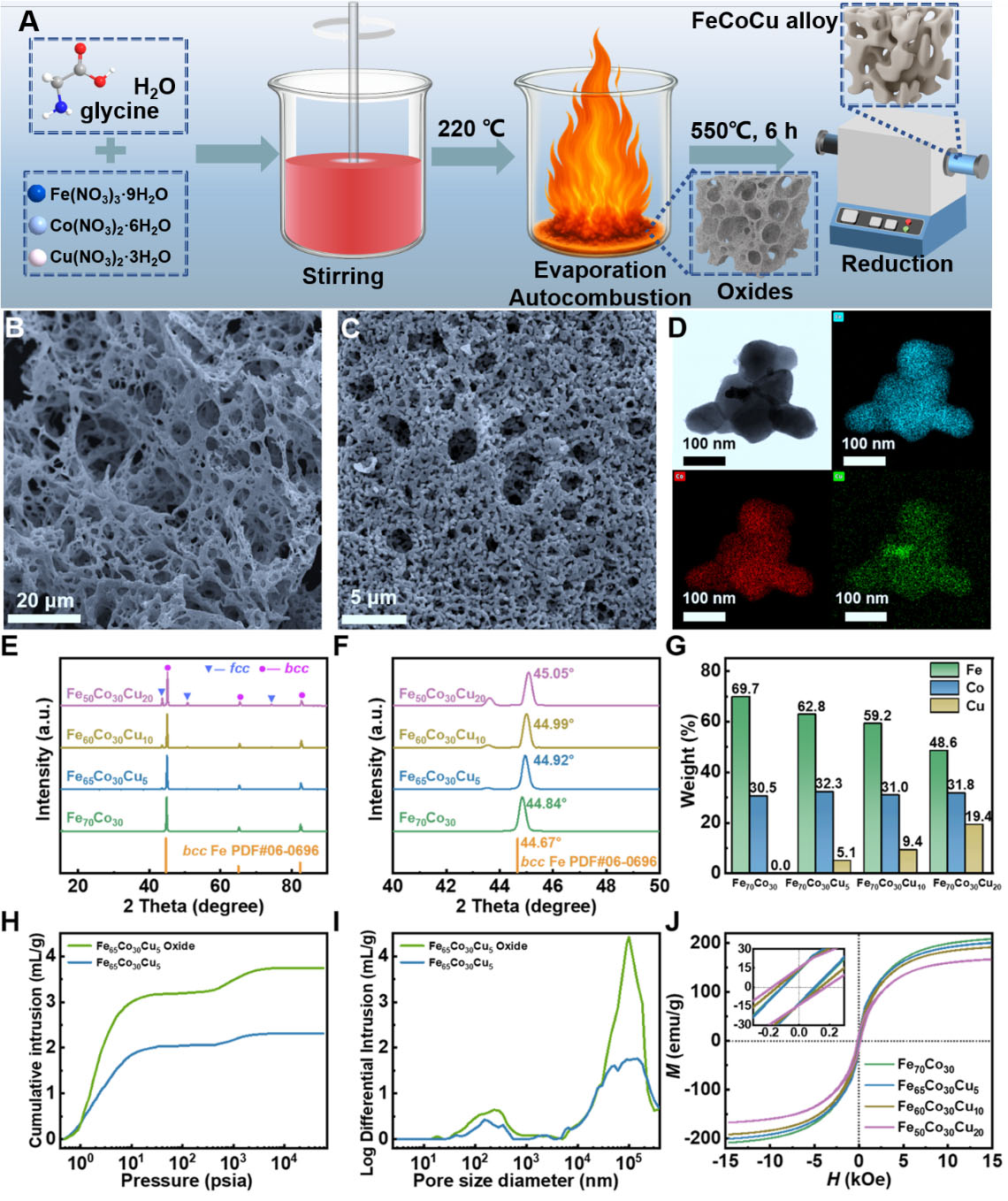
Figure 3. Synthesis process, structural evolution, and physicochemical characterization of FeCoCu alloy foams with different Cu contents. (A) Schematic illustration of the synthesis process; SEM images of (B) the Fe65Co30Cu5 oxide precursor; and (C) corresponding reduced Fe65Co30Cu5 alloy; (D) TEM image Fe65Co30Cu5 alloy and corresponding elemental mappings of Fe, Co, and Cu; (E) XRD patterns of FeCoCu alloys with varying Cu contents; and (F) corresponding enlarged XRD patterns in the 40-50° range; (G) ICP-derived elemental compositions of FeCoCu alloys with varying Cu contents; (H) Mercury intrusion cumulative pore volume curves of Fe65Co30Cu5 oxide precursor and reduced alloy; and (I) corresponding pore size distributions. (J) Magnetic hysteresis loops of FeCoCu alloys with varying Cu contents. SEM: TEM: XRD: X-ray diffraction; ICP: inductively coupled plasma.
XRD results [Figure 3E] reveal a transition from a single BCC phase in Fe70Co30 to a BCC/FCC dual-phase structure with increasing Cu content, consistent with limited Cu solubility and its tendency to induce phase separation[49]. The emergence of dual phases introduces additional interfaces, enhancing polarization loss. Meanwhile, the systematic peak shift from 44.84° to 45.05° [Figure 3F] indicates lattice modulation and increased structural distortion, further contributing to dielectric loss.
ICP-AES analysis was further performed to determine the experimental elemental compositions of the FeCoCu alloy foams. The compositions obtained from ICP-AES are presented as weight percentages in Figure 3G. The measured results confirm the intended composition regulation, with the Cu content increasing and the Fe content correspondingly decreasing, while the Co content remains nearly constant. Although slight deviations from the nominal atomic feeding ratios are observed, the overall composition trend is consistent with the designed Fe/Co/Cu ratios. Mercury intrusion results [Figure 3H and I] show that, although partial densification occurs during reduction (intrusion volume decreasing from 3.7 to 2.3 mL g-1), the hierarchical pore structure is largely retained. The resulting multiscale porosity simultaneously favors impedance matching and enhances multiple scattering, while the metallic framework supports conduction loss. Magnetic measurements [Figure 3J] indicate typical soft ferromagnetic behavior. The saturation magnetization decreases from 208.4 to 166.7 emu g-1 with increasing Cu content due to magnetic dilution, while coercivity increases from 105.6 to 177.0 Oe, reflecting structural evolution and enhanced anisotropy. Despite reduced magnetization, all samples retain sufficient magnetic response to support resonance-based magnetic losses, which are critical for impedance matching and bandwidth expansion.
Overall, FeCoCu foams achieve a synergistic regulation of composition, phase structure, and hierarchical porosity. Cu incorporation not only drives the BCC-to-BCC/FCC transition and increases interfacial density, but also introduces structural heterogeneity that enhances polarization loss. Combined with the three-dimensional porous framework and retained magnetic response, these features provide an integrated platform for tuning conduction, polarization, and magnetic losses. This synergy is essential for approaching the theoretically optimal absorption condition and enables efficient broadband EM wave absorption under thin-layer constraints.
Dielectric and magnetic loss behaviors of FeCoCu foam
To further elucidate the EM loss mechanisms and their composition dependence in FeCoCu foams, the complex εr, μr, and corresponding loss factors were systematically analyzed. As shown in Figure 4A and B, all samples exhibit pronounced frequency dispersion in the range of 2.00-18.00 GHz, with clear composition-dependent evolution. Specifically, both the εr' and εr'' increase markedly with increasing Cu content. The Fe70Co30 sample shows relatively low εr', decreasing from 6.0 to 4.8, whereas Fe65Co30Cu5 and Fe60Co30Cu10 exhibit higher and more stable values (8.0-10.5). Further increasing Cu to 20 at.% results in a substantial enhancement of εr', indicating significantly improved charge storage. A similar trend is observed for εr'', where Fe50Co30Cu20 maintains the highest values across the entire frequency range, confirming its strong energy dissipation capability. The tanδe values [Supplementary Figure 3] follow the same trend as εr'', increasing with Cu content. Fe70Co30 exhibits negligible loss, while Fe65Co30Cu5 and Fe60Co30Cu10 show moderate values. In contrast, Fe50Co30Cu20 reaches significantly higher levels, indicating more efficient EM energy dissipation. However, excessive dielectric loss may deteriorate impedance matching due to overly strong dielectric responses, implying that optimal EM wave absorption requires a balance between EM attenuation capability and impedance matching rather than maximizing EM loss alone.
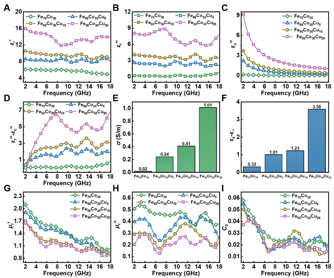
Figure 4. Composition-dependent EM parameters and dielectric loss mechanism decomposition of FeCoCu foams. (A) εr' values; (B) εr'' values; (C) εc'' values extracted from εr''; and (D) εr''-εc'' values of FeCoCu foams with various Cu contents; (E) Electrical conductivity values extracted from dielectric decomposition; and (F) εs-ε∞ values of FeCoCu foams with various Cu contents derived from dielectric analysis. (G) μr' values; (H) μr" values; and (I) C0 values of FeCoCu foams with various Cu contents. EM: Electromagnetic.
According to the Debye relaxation model and free electron theory, the imaginary permittivity can be expressed as the sum of conduction and polarization contributions[42,50]:
By fitting the experimental εr'' data using a least-squares method, the conduction loss component εc'' and polarization contribution εp'' were separated [Figure 4C and D]. As shown in Figure 4C, εc'' decreases with increasing frequency and increases significantly with Cu content. The Fe70Co30 sample exhibits negligible conduction loss, whereas the Cu-containing samples show progressively enhanced contributions, indicating improved electron transport. This is consistent with the fitted effective conductivity values extracted from the conduction loss term in the dielectric decomposition [Figure 4E], which increase from 0.02 to 1.01 S m-1 with increasing Cu content. Nevertheless, conduction loss alone cannot fully account for the observed dielectric behavior. As shown in Figure 4D, significant polarization loss remains after subtracting the conduction contribution, and this component also increases with Cu content. Fe70Co30 shows weak polarization, while Fe65Co30Cu5 and Fe60Co30Cu10 exhibit more pronounced fluctuations. The Fe50Co30Cu20 sample shows the strongest and most complex polarization behavior, with multiple peaks indicating active and diverse relaxation processes. This enhancement of polarization loss is closely associated with crystal structure evolution. As revealed by XRD analysis, increasing Cu content induces a transition from a single BCC phase to a BCC/FCC dual-phase structure, significantly increasing the density of heterogeneous interfaces. In addition, alloying-induced compositional fluctuations, lattice distortion, defects, and particle-particle contacts further contribute to interfacial charge accumulation under alternating EM fields, leading to Maxwell-Wagner polarization. The hierarchical porous structure, combined with nanoscale heterogeneity, further promotes dipolar relaxation. Therefore, the role of Cu extends beyond improving conductivity - it fundamentally enhances polarization by introducing structural heterogeneity and interfacial complexity, enabling the synergistic coupling of conduction and polarization losses.
To further investigate relaxation behavior, Cole-Cole plots were constructed from εr' and εr'' [Supplementary Figure 4A-D]. According to classical Debye theory, a single relaxation process corresponds to a perfect semicircle, whereas multiple semicircles, distorted arcs, and tailing features indicate the coexistence of multiple relaxation processes and conduction effects. All samples exhibit multiple semicircles and distorted arcs, confirming that FeCoCu foams involve complex and multi-scale relaxation processes rather than a single Debye relaxation. This further supports the conclusion that broadband dielectric loss in this system originates from the cooperative contribution of conduction loss, interfacial polarization, and dipolar relaxation.
To more intuitively quantify the synergistic evolution of conduction and polarization losses induced by Cu incorporation, an equivalent circuit model [Supplementary Figure 5] was employed to describe EWAMs that simultaneously exhibit conduction and polarization dissipation.[51] In this model, the parallel branch represents conduction loss dominated by free electron transport, while the series branch accounts for polarization loss associated with dipolar relaxation and interfacial polarization. By establishing a correspondence between the complex permittivity of the equivalent circuit and the modified Debye model, the frequency-dependent EM response can be transformed into physically meaningful circuit parameters, including the parallel conductivity (σ1), parallel capacitance (ε1), series conductivity (σ2), and series capacitance (ε2).
The equivalent complex permittivity of the circuit can be expressed as[52, 53]:
which can be rearranged into:
According to the modified Debye relaxation model, the complex permittivity can also be written as[54]:
By comparing Equations (16) and (17), the following relationships can be obtained:
In this equivalent circuit model, σ1 represents the conductivity of the parallel conduction branch, which mainly reflects free-electron transport and leakage-current loss. ε1 is the absolute permittivity term of the parallel branch and corresponds to the high-frequency dielectric storage contribution, i.e., ε1 = ε0ε∞. The series branch is used to describe polarization relaxation. ε2 represents the absolute permittivity contribution associated with the relaxation strength, i.e., ε2 = ε0(εs-ε∞), while σ2 is the equivalent dissipative conductivity of the polarization branch and is given by σ2 = ε2/τ = ε0(εs-ε∞)/τ. It should be noted that ε1 and ε2 are not dimensionless relative permittivity or lumped capacitance of a specific circuit geometry; rather, they are equivalent material parameters with units of pF m-1. By contrast, σ1 and σ2 have units of S m-1. Therefore, once σ, ε∞, εs- ε∞, and τ are determined, the corresponding equivalent circuit parameters can be quantitatively calculated.
Because the Cole-Cole plots of FeCoCu foams are distorted by conduction effects and multiple relaxation processes, the dielectric response cannot be described by an ideal single-Debye semicircle over the whole frequency range. Therefore, the equivalent circuit analysis in this work should be regarded as an effective and semi-quantitative description of the dominant dielectric relaxation behavior. To reduce the influence of conduction loss, the measured imaginary permittivity was first analyzed using the modified Debye model containing both polarization and conduction terms. The conduction contribution was separated according to the free-electron term, and the remaining polarization-related response was used to estimate the dominant relaxation parameters. In the Cole-Cole representation, the fitted dominant relaxation arc satisfies[54]:
where the center and radius of the fitted arc provide εs + ε∞ and εs - ε∞, respectively. The relaxation time τ was determined from the characteristic relaxation frequency corresponding to the maximum polarization loss, according to ωτ = 1. It should be noted that these parameters represent effective values of the dominant relaxation process rather than unique microscopic constants. Nevertheless, the extracted parameters are reliable for comparing the composition-dependent dielectric evolution because the same fitting procedure was applied to all samples, the obtained τ values remain nearly unchanged, and the monotonic increase in εs - ε∞ is consistent with the enhanced interfacial polarization induced by the BCC/FCC dual-phase structure and compositional heterogeneity [Figure 4F]. Therefore, the subsequent equivalent circuit analysis mainly reflects the relative enhancement of conduction and polarization branches with increasing Cu content.
The extracted εs + ε∞ values are provided in Supplementary Figure 6A. The characteristic τ values for Fe70Co30, Fe65Co30Cu5, Fe60Co30Cu10, and Fe50Co30Cu20 are 11.84, 11.73, 11.76, and 11.88 ps, respectively [Supplementary Figure 6B], showing negligible variation. The equivalent circuit parameters are summarized in Table 1. From the parallel branch perspective, σ1 increases monotonically from 0.02 to 1.01 S m-1 with increasing Cu content, indicating a continuous enhancement of charge transport and conduction loss. This behavior originates from both the intrinsically high conductivity of Cu and the improved connectivity of conductive pathways, reduced transport barriers, and enhanced particle contact within the porous framework. Meanwhile, ε1 increases from 47.59 to 100.49 pF m-1, suggesting a strengthened high-frequency dielectric response and enhanced energy storage capability. More importantly, the series branch parameters exhibit a much stronger increase. The polarization-related capacitance ε2 rises sharply from 2.83 to 31.70 pF m-1, while σ2 increases from 0.24 to 2.67 S m-1. Given that τ remains nearly constant (11.8 ps), this enhancement is primarily attributed to the increase in εs - ε∞ rather than changes in relaxation dynamics. This indicates that Cu incorporation does not introduce new relaxation mechanisms but amplifies existing ones by increasing the density and strength of polarization-active sites. Notably, the increase in ε2 and σ2 is significantly more pronounced than that of σ1 and ε1, especially at high Cu content. This suggests that polarization loss is more sensitive to Cu incorporation than conduction loss. Such behavior is closely related to structural evolution: Cu induces a transition from a single BCC phase to a BCC/FCC dual-phase system, increasing interfacial density, compositional heterogeneity, and defect concentration. These features promote Maxwell-Wagner interfacial polarization and dipolar relaxation, thereby significantly enhancing dielectric loss. The nearly invariant τ further indicates that the dominant polarization mechanism remains fundamentally unchanged. Instead, Cu enhances dielectric loss primarily by amplifying polarization intensity rather than shifting relaxation frequency.
Equivalent circuit parameters of FeCoCu alloys with different Cu contents
| Fe70Co30 | Fe65Co30Cu5 | Fe60Co30Cu10 | Fe50Co30Cu20 | |
| σ1 (S m-1) | 0.02 | 0.24 | 0.41 | 1.01 |
| ε1 (pF m-1) | 47.59 | 68.40 | 75.97 | 100.49 |
| σ2 (S m-1) | 0.24 | 0.76 | 0.93 | 2.67 |
| ε2 (pF m-1) | 2.83 | 8.94 | 10.89 | 31.70 |
In addition to dielectric behavior, the magnetic response also shows clear composition dependence. As shown in Figure 4G, μr' values decrease with increasing Cu content due to magnetic dilution, while μr" values [Figure 4H] remain in the range of 0.1-0.6 and exhibit frequency-dependent fluctuations, indicating multiple magnetic loss mechanisms. The magnetic loss factor (tanδm, Supplementary Figure 7) remains within a moderate range (0.1-0.4), suggesting that although Cu reduces overall magnetization, sufficient magnetic dissipation is retained. This moderate and frequency-selective magnetic loss is beneficial for improving impedance matching. To further clarify the magnetic loss mechanism, the eddy current coefficient was calculated[41]:
As shown in Figure 4I, C0 is not constant with frequency, indicating that magnetic loss is not solely governed by eddy current effects but involves natural resonance and exchange resonance.
Overall, Cu incorporation induces a synergistic enhancement of conduction, polarization, and magnetic losses. While conductivity increases strengthen conduction loss, the formation of heterogeneous interfaces significantly amplifies polarization loss. Meanwhile, sufficient magnetic loss is preserved despite partial magnetic dilution. Therefore, the FeCoCu system achieves a cooperative coupling of multiple loss mechanisms, which is essential for realizing broadband electromagnetic wave absorption.
EM absorption performance and loss mechanism analysis
Further evaluation of the EM wave absorption performance of FeCoCu alloy foams with different Cu contents was conducted, as shown in Figure 5. The three-dimensional reflection loss maps reveal that the Cu content plays a decisive role in determining the absorption behavior. The Fe70Co30 sample exhibits a minimum reflection loss of -20.8 dB [Figure 5A], indicating a certain absorption capability, although both the absorption intensity and bandwidth remain limited. After introducing 5 at.% Cu, the RLmin of Fe65Co30Cu5 decreases markedly to -52.9 dB [Figure 5B], demonstrating a substantial improvement in microwave attenuation. When the Cu content is further increased to 10 at.%, Fe60Co30Cu10 still maintains strong absorption ability, with an RLmin of -26.7 dB [Figure 5C]. However, when the Cu content reaches 20 at.%, the RLmin of Fe50Co30Cu20 increases to only -11.8 dB [Figure 5D], indicating a significant deterioration of absorption performance. These results suggest that Cu incorporation is not monotonically beneficial. Although excessive Cu can enhance dielectric loss, it may simultaneously weaken magnetic loss and induce impedance mismatch, thereby suppressing the penetration of incident electromagnetic waves into the absorber. The two-dimensional reflection loss maps further clarify the differences in EABs among the samples. Fe70Co30 achieves a maximum EAB of 5.36 GHz with coating thickness of 2.18 mm [Figure 5E], whereas Fe65Co30Cu5 delivers the widest bandwidth of 7.36 GHz with coating thickness of only 1.74 mm [Figure 5F], exhibiting the best broadband absorption performance. Fe60Co30Cu10 also maintains a considerable effective bandwidth of 6.00 GHz with coating thickness of 1.67 mm [Figure 5G]. In contrast, Fe50Co30Cu20 shows a much narrower maximum effective bandwidth of only 1.36 GHz with a coating thickness of 1.72 mm [Figure 5H]. Combined with the preceding electromagnetic parameter analysis, these results indicate that an appropriate Cu content can simultaneously enhance conduction loss and interfacial polarization loss while preserving sufficient magnetic loss. In contrast, excessive Cu leads to overly strong dielectric response and weakened magnetic response, resulting in severe impedance mismatch and enhanced surface reflection, thereby limiting broadband absorption.
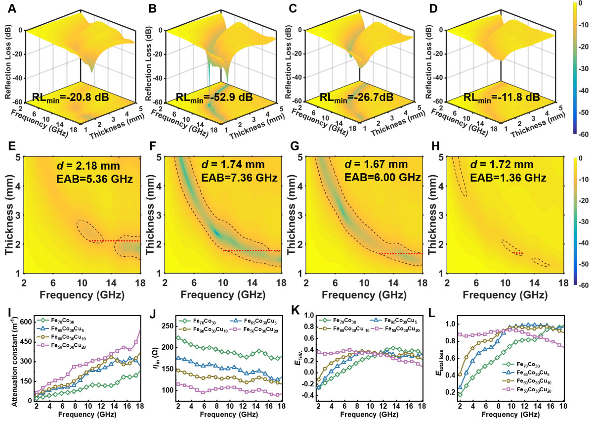
Figure 5. EM wave absorption performance and loss mechanism analysis of FeCoCu alloy foams with different Cu contents. Three-dimensional reflection loss maps of (A) Fe70Co30, (B) Fe65Co30Cu5, (C) Fe60Co30Cu10 and (D) Fe50Co30Cu20, respectively. Corresponding two-dimensional reflection loss contour maps of (E) Fe70Co30, (F) Fe65Co30Cu5, (G) Fe60Co30Cu10 and (H) Fe50Co30Cu20, respectively. The dashed contour lines indicate RL = −10 dB, and the maximum EABs are marked in the corresponding panels. Frequency-dependent (I) attenuation constant, (J) input impedance, (K) interference loss contribution, and (L) total energy loss contribution are presented to clarify the EM absorption mechanism. EM: Electromagnetic; RL: reflection loss; EAB: effective absorption bandwidth.
A comparative summary of representative magnetic metal-, alloy-, foam/aerogel-, and Cu-containing EWAMs is provided in Table 2 to place the EM wave absorption performance of the present FeCoCu alloy foam in context. The comparison includes coating thickness, minimum RL, EAB, and frequency range. Compared with many reported EWAMs, the present FeCoCu alloy foam exhibits a broad EAB with relatively thin coating thickness, demonstrating the effectiveness of the frequency thickness normalized EM parameter design strategy.
Comparison of EM wave absorption performance between this work and representative magnetic metal-, alloy-, foam/aerogel-, and Cu-containing EWAMs
| EWAMs | RLmin (dB) | EAB (GHz) | Thickness (mm) | Refs |
| Flower like α-Fe | -33.1 | 6.2 (7.7-13.9) | 3.00 | [55] |
| Cobalt particles | -48.0 | 6.8 (11.2-18.0) | 1.70 | [56] |
| FeCo alloys | -53.6 | 6.8 (11.2-18.0) | 1.55 | [57] |
| FeCoNiCr0.4Mn0.6 | -48.5 | 5.4 (8.7-14.1) | 2.00 | [58] |
| Fe3O4 foam | -26.0 | 6.2 (11.8-18.0) | 1.80 | [59] |
| Mxene/C aerogels | -53.0 | 5.3 (7.4-12.7) | 2.40 | [60] |
| Dendrite-like NiCu alloy | -21.1 | 3.4 (13.4-16.8) | 1.40 | [61] |
| FeCoCu alloy foam | -52.9 | 7.36 (10.64-18.00) | 1.74 | This work |
To further elucidate the origin of these performance differences, the attenuation capability (α), input impedance characteristics (ηin), interference loss (E1/4λ), and total energy dissipation (Etotal loss) can be calculated using the following equations[33,41,62,63].
where the factor T reflects the attenuation of the EM wave, Π represents reflection at the metal backplate, and ϕ is the phase difference between Π and Γ. As shown in Figure 5I, the attenuation constant increases with increasing Cu content, and Fe50Co30Cu20 exhibits the highest attenuation capability, suggesting the strongest conductive and polarization losses. However, strong attenuation alone does not necessarily guarantee superior EM wave absorption performance, because EM attenuation can only contribute effectively after incident EM waves enter the EWAM. Excessive Cu incorporation greatly enhances dielectric loss but simultaneously weakens the magnetic response, leading to a large impedance mismatch between the EWAM and free space. As a result, strong surface reflection occurs at the air/EWAM interface, and only a limited fraction of the incident EM wave can penetrate into the EWAM for subsequent dissipation. Therefore, in the high-Cu sample, impedance matching becomes the decisive prerequisite rather than EM attenuation strength. In contrast, Fe65Co30Cu5 possesses moderate dielectric loss, sufficient polarization/conduction dissipation, and retained magnetic response, which collectively lead to a more favorable input impedance. Meanwhile, its EM parameters better satisfy the quarter-wavelength cancellation condition over a broader frequency range. Thus, Fe65Co30Cu5 achieves the best balance among impedance matching, attenuation capability, and destructive interference, resulting in the widest EAB and strongest overall EM wave absorption performance.
Figure 5J shows that the input impedance decreases with increasing Cu content, indicating that high-Cu samples possess a larger impedance difference from free space, which hinders the effective entry of incident EM waves into the EWAM. Therefore, although Fe50Co30Cu20 exhibits the strongest attenuation, its poor impedance matching results in the weakest actual absorption performance.
The interference loss contribution shown in Figure 5K further confirms the importance of the quarter-wavelength cancellation condition in determining the absorption peak position and effective bandwidth. Fe65Co30Cu5 and Fe60Co30Cu10 exhibit relatively favorable interference loss contributions over a broad frequency range, indicating that their EM parameters and matching thicknesses are closer to the ideal absorption conditions proposed in the theoretical analysis[64]. The total energy loss contribution in Figure 5L further demonstrates that Fe65Co30Cu5 and Fe60Co30Cu10 can both achieve high energy dissipation in the middle- and high-frequency regions. Among them, Fe65Co30Cu5 achieves the best balance among strong attenuation, impedance matching, and destructive interference, thereby yielding the lowest RLmin and the broadest EAB.
Overall, the EM absorption performance of FeCoCu alloy foams is not governed by a single loss mechanism, but by the synergistic effects of conduction loss, polarization loss, magnetic loss, impedance matching, and interference cancellation. An appropriate Cu content enables the construction of a moderately conductive network and abundant heterogeneous interfaces while retaining the magnetic response of the FeCo matrix. Such a balance realizes the coordinated optimization of attenuation capability, impedance matching, and interference loss, which is essential for achieving thin, efficient, and broadband EM wave absorption.
RCS reduction simulation and multilayer structural design
To further assess the application potential of FeCoCu foams in practical metal-backed stealth scenarios, CST simulations were conducted to evaluate their radar cross-section reduction capability. As illustrated in Figure 6A, FeCoCu foams with a thickness of 1.75 mm were coated onto a 1.0 mm-thick PEC layer to construct a metal-backed EM absorbing structure, and the RCS response was analyzed in the frequency range of 2.00-18.00 GHz. Figure 6B shows that the RCS of the bare PEC layer increases with frequency, confirming its strong reflection toward incident EM waves. In contrast, after coating with FeCoCu EM absorbing layers, the RCS values decrease to different extents. Among all samples, Fe65Co30Cu5 exhibits the most pronounced RCS reduction, with values significantly lower than those of the bare PEC layer and other compositions. This result is consistent with the reflection loss analysis, in which Fe65Co30Cu5 exhibits both the lowest RLmin and the widest EAB, indicating that its optimized impedance matching and synergistic loss mechanisms can effectively suppress the backscattering of metallic targets. Figure 6C further compares the RCS reduction of the Fe65Co30Cu5-coated PEC layer with respect to the bare PEC layer, together with the absolute value of the reflection loss at the same thickness. The RCS reduction curve agrees well with the -RL curve in terms of frequency dependence, and both reach their maximum near 13.00-14.00 GHz. This consistency suggests that the absorption peak revealed by the transmission-line model can be effectively translated into practical scattering suppression. In other words, Fe65Co30Cu5 not only exhibits excellent EM absorption performance in the theoretical reflection loss calculation, but also achieves significant RCS reduction in a more realistic electromagnetic scattering model. For comparison, the RCS reduction behaviors of the other FeCoCu-coated PEC structures are shown in Supplementary Figure 8A-C. Their RCS reduction curves also exhibit frequency-dependent trends that generally follow the corresponding -RL curves, confirming that the reflection loss characteristics of these EWAMs are closely related to their scattering suppression capability. However, their RCS reduction intensities are weaker than that of Fe65Co30Cu5. Fe70Co30 shows limited RCS reduction because of insufficient dielectric attenuation, whereas Fe50Co30Cu20 exhibits reduced scattering suppression despite its high attenuation capability, which can be attributed to severe impedance mismatch caused by excessive dielectric loss. Fe60Co30Cu10 presents an intermediate behavior, consistent with its moderate absorption performance. These results further demonstrate that effective RCS reduction requires a balanced combination of impedance matching and energy dissipation rather than simply maximizing the loss capability.
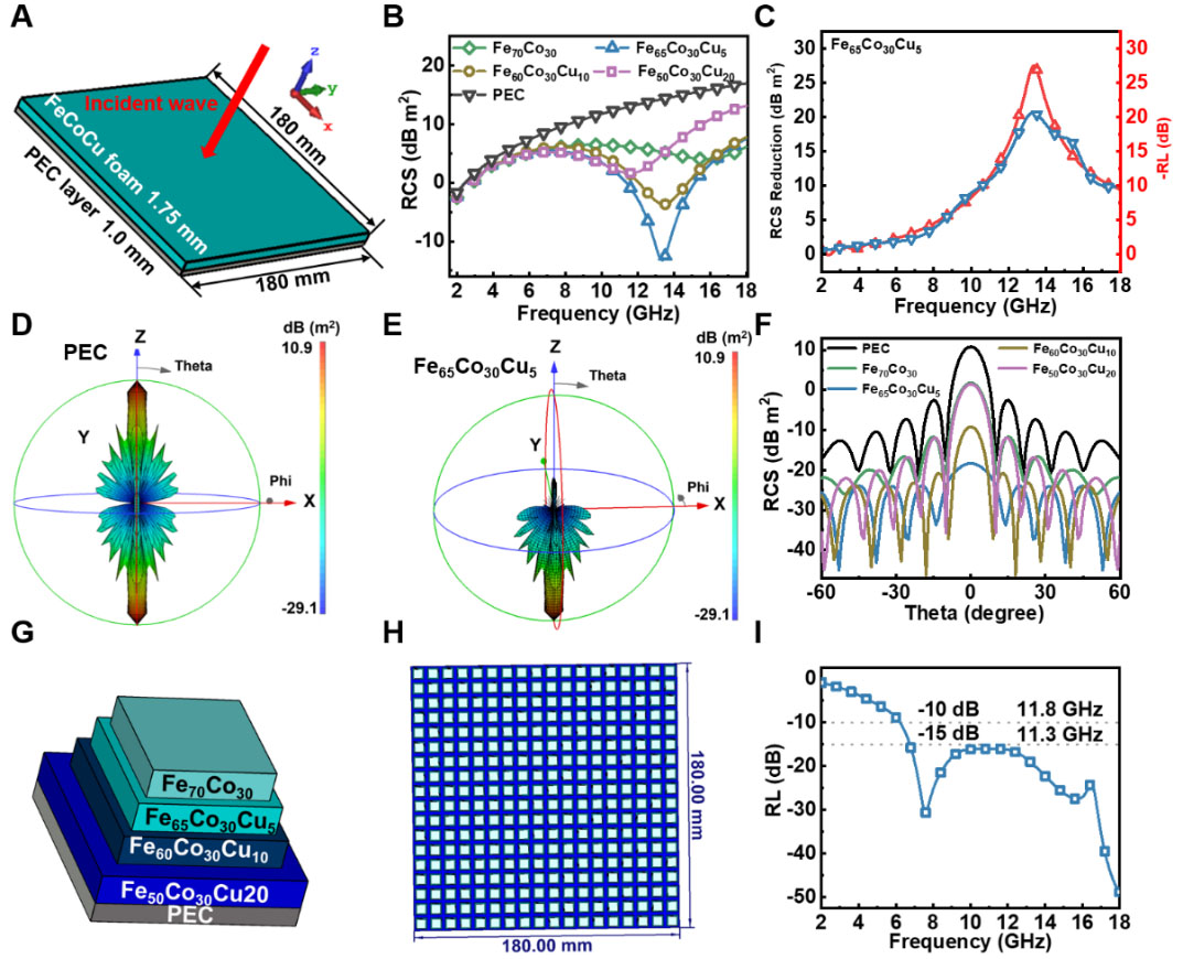
Figure 6. RCS simulation and structural design of FeCoCu-based EWAMs. (A) CST simulation model of FeCoCu foam coated on a PEC layer; (B) RCS values of PEC and FeCoCu-coated PEC layers; (C) RCS reduction of Fe65Co30Cu5-coated PEC compared with bare PEC, together with the corresponding -RL curve. Three-dimensional RCS patterns of (D) bare PEC; and (E) Fe65Co30Cu5-coated PEC, respectively; (F) Angular RCS distributions of PEC and FeCoCu-coated PEC layers. (G and H) Schematic model of the multilayer frequency-selective structure based on FeCoCu alloys with different Cu contents; (I) Reflection loss curve of the multilayer frequency-selective EWAMs. RCS: Radar cross-section; PEC: EWAM: electromagnetic wave absorbing material.
The angular RCS distributions further confirm the scattering regulation capability of the EM absorbing coating. Figure 6D shows that the bare PEC layer exhibits strong scattering over different azimuth and elevation angles, especially with a pronounced main scattering lobe along the specular reflection direction. In comparison, after coating with 1.75 mm Fe65Co30Cu5, the overall RCS intensity is greatly reduced, the main scattering lobe is significantly compressed, and the side scattering is also effectively suppressed, as shown in Figure 6E. The three-dimensional RCS patterns of Fe70Co30, Fe60Co30Cu10, and Fe50Co30Cu20 are provided in Supplementary Figure 8D-F. Although these coatings also suppress the scattering intensity relative to the bare PEC layer, their reduction effects are less pronounced than that of Fe65Co30Cu5, further verifying the superior angular scattering suppression capability of the optimally Cu-modulated sample. Figure 6F presents the angular RCS curves at different incident angles. The bare PEC layer shows the strongest scattering near 0°, whereas all FeCoCu-coated structures exhibit different degrees of RCS reduction over a broad angular range. Among them, Fe65Co30Cu5 shows the most obvious scattering suppression under normal and near-normal incidence, indicating that its absorption capability is not limited to frequency-domain optimization but also possesses favorable angular adaptability. Based on the preceding dielectric, magnetic, and impedance analyses, this performance can be attributed to the optimized balance among conduction loss, interfacial polarization loss, and magnetic loss induced by moderate Cu incorporation. Such a balance allows EM waves to enter the EWAMs efficiently while being sufficiently dissipated. In contrast, excessive Cu enhances attenuation capability but tends to cause impedance mismatch, thereby limiting RCS reduction.
On this basis, a multilayer frequency-selective surface structure was further designed to broaden the EM absorption bandwidth, as shown in Figure 6G and Figure 6H. The multilayer unit consisted of a 1.0 mm-thick PEC backing layer and four EM absorbing layers, each with a coating thickness of 1.5 mm. The lateral dimensions of the four EM absorbing layers were 6.0, 7.0, 8.0, and 10.0 mm from top to bottom, respectively. In this structure, FeCoCu foams with different Cu contents were introduced into different layers of the frequency-selective units, enabling each layer to contribute to impedance regulation and energy dissipation in different frequency regions. Because FeCoCu foams with different Cu contents possess distinct dielectric losses, magnetic responses, and impedance matching characteristics, the multilayer configuration can construct a gradient distribution of EM parameters along the propagation direction. This gradient structure reduces the impedance discontinuity at the air/EWAM interface and promotes broadband synergistic EM absorption through multiple reflections, destructive interference, and multi-mechanism energy dissipation. As shown in Figure 6I, the multilayer frequency-selective structure exhibits an ultrabroad absorption bandwidth, with the RL below -10 dB reaching 11.8 GHz and that below -15 dB still reaching 11.3 GHz, significantly outperforming the single-layer homogeneous EWAMs. This result demonstrates that integrating the composition-dependent EM responses of FeCoCu foams with structural design can overcome the trade-off between impedance matching and loss intensity in a single material system, thereby enabling efficient EM wave absorption over a much wider frequency range[65]. It also further validates the design principle proposed in this work: broadband absorption should not rely solely on high loss, but requires the coordinated optimization of conduction loss, polarization loss, magnetic loss, impedance matching, and interference cancellation.
CONCLUSIONS
In this work, a theory-guided strategy was proposed to address the challenge of achieving broadband EM wave absorption in thin metal-backed EWAMs. Based on transmission-line theory, the ideal frequency-thickness-dependent permittivity relationship required for broadband absorption was first constructed. Theoretical analysis revealed that excellent absorption can be achieved when the EM parameters simultaneously satisfy appropriate impedance matching, quarter-wavelength cancellation, and sufficient energy attenuation. Further calculations demonstrated that single conduction loss or polarization loss has an intrinsic limitation in bandwidth, whereas the introduction of magnetic response can further broaden the EABs.
Guided by this theoretical framework, FeCoCu alloy foams with tunable Cu contents were designed and synthesized. Structural characterization confirmed that Cu incorporation induced the evolution from a single BCC phase to a BCC/FCC dual-phase structure, generating abundant heterogeneous interfaces while maintaining the porous FeCo-based magnetic framework. EM parameter and equivalent circuit analyses demonstrated that increasing Cu content enhanced both conduction loss and polarization loss, while the FeCo matrix retained considerable magnetic loss. However, excessive Cu caused overly strong dielectric response and impedance mismatch, indicating that high loss alone is insufficient for broadband absorption. Among all samples, Fe65Co30Cu5 exhibited the best balance among attenuation capability, impedance matching, and interference cancellation, achieving a minimum reflection loss of -52.9 dB and an EAB of 7.36 GHz with coating thickness of only 1.74 mm. CST simulations further confirmed its capability for RCS reduction on a PEC substrate. Moreover, a multilayer frequency-selective structure based on FeCoCu foams achieved ultrabroadband absorption, with bandwidths of 11.8 GHz and 11.3 GHz below -10 and -15 dB, respectively. These results verify the effectiveness of combining theoretical EM parameter design with compositional and structural regulation for developing thin, efficient, and broadband EWAMs.
DECLARATIONS
Acknowledgments
The authors gratefully acknowledge Shuping Yu from Fudan University for her valuable assistance with the MATLAB-based theoretical calculations, including the use of her computational software and her support in writing part of the MATLAB codes. The authors also sincerely thank Lixue Gai from Henan Academy of Sciences for her helpful assistance with the CST Microwave Studio simulations.
Authors’ contributions
Conceptualization: Hu, B.; Du, Y.
Data curation: Hu, B.; Song, W.; Chen, Y. (Yongzheng Chen)
Formal analysis: Hu, B.; Chen, Y. (Yanyi Chen); Han, X.; Du, Y.
Software: Hu, B.; Chen, Y. (Yongzheng Chen); Wang, X.
Visualization: Hu, B.; Song, W.; Chen, Y. (Yongzheng Chen)
Writing-original draft: Hu, B.; Chen, Y. (Yanyi Chen)
Investigation: Chen, Y. (Yanyi Chen); Wang, X.; Du, Y.
Validation: Chen, Y. (Yanyi Chen)
Methodology: Song, W.; Chen, Y. (Yongzheng Chen)
Resources: Song, W.; Chen, Y. (Yongzheng Chen); Wang, X.
Supervision: Han, X.; Du, Y.
Project administration: Han, X.; Du, Y.
Funding acquisition: Han, X.; Du, Y.
Writing-review & editing: Du, Y.
Availability of data and materials
All data needed to evaluate the conclusions are available in the manuscript and the Supplementary Materials.
Ethical approval and consent to participate
Not applicable.
AI and AI-assisted tools statement
Not applicable.
Financial support and sponsorship
This work was supported by the National Natural Science Foundation of China (No. 22475057 and No. 52373262).
Conflicts of interest
All authors declared that there are no conflicts of interest.
Consent for publication
Not applicable.
Copyright
© The Author(s) 2026.
Supplementary Materials
REFERENCES
1. Shi, M.; Jia, Z.; Lan, D.; Gao, Z.; Zhang, S.; Wu, G. Enhanced polarization relaxation of multidimensional bimetallic selenide nanocomposites for electromagnetic wave absorption. Adv. Funct. Mater. 2025, 35, e02261.
2. Cai, B.; Zhou, L.; Zhao, P. Y.; et al. Interface-induced dual-pinning mechanism enhances low-frequency electromagnetic wave loss. Nat. Commun. 2024, 15, 3299.
3. Davies, N.; Williams, C.; Osborne, M.; Dogan, H.; Ki-Aries, D.; Jiang, N. Electromagnetic warfare intentional interference: victim risk assessment. IEEE. Trans. Electromagn. Compat. 2026, 68, 143-51.
4. He, M.; Zhang, K.; Qiu, H.; et al. Low-frequency microwave absorption composites. Adv. Sci. (Weinh). 2025, 12, e11580.
5. Liang, Q.; He, M.; Zhan, B.; et al. Yolk-shell CoNi@N-doped carbon-CoNi@CNTs for enhanced microwave absorption, photothermal, anti-corrosion, and antimicrobial properties. Nanomicro. Lett. 2025, 17, 167.
6. Balci, O.; Polat, E. O.; Kakenov, N.; Kocabas, C. Graphene-enabled electrically switchable radar-absorbing surfaces. Nat. Commun. 2015, 6, 6628.
7. Shi, Y.; Liang, B.; Gao, H.; et al. Research progress on spherical carbon-based electromagnetic wave absorbing composites. Carbon 2024, 227, 119244.
8. Pan, F.; Pei, K.; Chen, G.; et al. Integrated electromagnetic device with on-off heterointerface for intelligent switching between wave-absorption and wave-transmission. Adv. Funct. Mater. 2023, 33, 2306599.
9. Tariq, M. R.; Ahmad, M.; Naik, M.; Khan, I.; Zhang, B. A comprehensive review of the advancement of transition metal oxide nanocomposites for microwave absorption. Coord. Chem. Rev. 2025, 533, 216535.
10. Wang, N.; Kou, X.; Zhong, L.; et al. Geometry-defect-spin coupling in chiral high-entropy systems: Multiscale mechanisms of GHz electromagnetic dissipation. Sci. Adv. 2025, 11, eadz2218.
11. He, Q.; Kou, X.; Huang, H.; et al. Combustion-driven lattice reconstruction activates electron spin and densifies electronic states for synergistic broadband microwave absorption. Adv. Funct. Mater. 2026, 36, e28574.
12. Rabchinskii, M. K.; Shiyanova, K. A.; Brzhezinskaya, M.; et al. Chemistry of reduced graphene oxide: implications for the electrophysical properties of segregated graphene-polymer composites. Nanomaterials. (Basel). 2024, 14, 1664.
13. Liu, X.; Zhao, Y.; Zhang, Y.; et al. Bioinspired layered-gradient nanocomposites for intelligent electromagnetic skins with GHz-THz wave absorption, shielding, and solvent-driven actuation. Nanomicro. Lett. 2026, 18.
14. Yang, L.; Wang, Y.; Lu, Z.; Cheng, R.; Wang, N.; Li, Y. Construction of multi-dimensional NiCo/C/CNT/rGO aerogel by MOF derivative for efficient microwave absorption. Carbon 2023, 205, 411-21.
15. Wu, L.; Gao, H.; Guo, R.; et al. MnO2 intercalation-guided impedance tuning of carbon/polypyrrole double conductive layers for electromagnetic wave absorption. Chem. Eng. J. 2023, 460, 141749.
16. Wang, H.; Zhang, H.; Zhao, K.; et al. Research progress on electromagnetic wave absorption based on magnetic metal oxides and their composites. Adv. Compos. Hybrid. Mater. 2023, 6, 694.
17. Jiang, J.; Lan, D.; Li, Y.; et al. Construction of spherical heterogeneous interface on ZnFe2O4@C composite nanofibers for highly efficient microwave absorption. Ceram. Int. 2024, 50, 38331-41.
18. Liu, S.; Shen, C.; Deng, Z.; et al. Non-equilibrium pyrolysis enables nano-confined hetero-interfaces in MOF-derivatives for advanced dielectric engineering. Adv. Funct. Mater. 2026, 36, e75267.
19. Han, Y.; Guo, H.; Qiu, H.; et al. Multimechanism decoupling for low-frequency microwave absorption hierarchical Fe-doped Co magnetic microchains. Adv. Funct. Materials. 2025, 35, 2506803.
20. Jia, Z.; Sun, L.; Gao, Z.; Lan, D. Modulating magnetic interface layer on porous carbon heterostructures for efficient microwave absorption. Nano. Res. 2024, 17, 10099-108.
21. Chen, N.; Wang, R.; Pan, X.; et al. Hollow engineering of core-shell Fe3O4@MoS2 microspheres with controllable interior toward optimized electromagnetic attenuation. Adv. Compos. Hybrid. Mater. 2025, 8, 1393.
22. Feng, S.; Wang, H.; Ma, J.; et al. Fabrication of hollow Ni/NiO/C/MnO2@polypyrrole core-shell structures for high-performance electromagnetic wave absorption. Compos. Part. B-Eng. 2024, 275, 111344.
23. Rozanov, K. Ultimate thickness to bandwidth ratio of radar absorbers. IEEE. Trans. Antennas. Propagat. 2000, 48, 1230-4.
24. Duan, Y.; Gu, S.; Ma, B.; et al. Metamaterial absorbers with archimedean tiling structures: toward response and absorption of multiband electromagnetic waves. ACS. Appl. Mater. Interfaces. 2024, 16, 21255-63.
25. Huang, L.; Duan, Y.; Liu, J.; et al. Bionic composite metamaterials for harvesting of microwave and integration of multifunctionality. Compos. Sci. Technol. 2021, 204, 108640.
26. Wei, K.; Shi, Y.; Tan, X.; et al. Recent development of metal-organic frameworks and their composites in electromagnetic wave absorption and shielding applications. Adv. Colloid. Interface. Sci. 2024, 332, 103271.
27. Li, F.; Li, Q.; Kimura, H.; et al. Morphology controllable urchin-shaped bimetallic nickel-cobalt oxide/carbon composites with enhanced electromagnetic wave absorption performance. J. Mater. Sci. Technol. 2023, 148, 250-9.
28. Liu, T.; Li, L.; Gao, P.; Li, L.; Cao, M. High-entropy electromagnetic functional materials: From electromagnetic genes to materials design. Mater. Sci. Eng. R. Rep. 2025, 164, 100982.
29. Qiu, Z.; Liu, X.; Yang, T.; et al. Synergistic enhancement of electromagnetic wave absorption and corrosion resistance properties of high entropy alloy through lattice distortion engineering. Adv. Funct. Mater. 2024, 34, 2400220.
30. Yu, L.; Lan, D.; Guo, Z.; et al. Multi-level hollow sphere rich in heterojunctions with dual function: Efficient microwave absorption and antiseptic. J. Mater. Sci. Technol. 2024, 189, 155-65.
31. He, Y.; Su, Q.; Liu, D.; et al. Surface engineering strategy for MXene to tailor electromagnetic wave absorption performance. Chem. Eng. J. 2024, 491, 152041.
32. Wu, G.; Han, Y.; Lan, D.; et al. Polyaniline decorative MnCo2O4.5 microspheres coupled with CoNi layered double hydroxides with remarkable electromagnetic wave absorption capacity. Carbon 2025, 244, 120631.
33. Han, Y.; Yang, Y.; Li, T.; et al. Hierarchical heterogeneous co-based magnetic absorbers for superior broadband high-efficiency microwave absorption. Adv. Funct. Mater. 2026, 36, e25719.
34. Siddiki, S. H.; Maity, C. K.; Sahoo, S. Advances in microwave-absorbing materials: from fundamentals to emerging technologies. J. Mater. Chem. A. 2025, 13, 31869-920.
35. Zeng, X.; Cheng, X.; Yu, R.; Stucky, G. D. Electromagnetic microwave absorption theory and recent achievements in microwave absorbers. Carbon 2020, 168, 606-23.
36. Peng, H.; Zhang, D.; Xie, Z.; Lu, S.; Liu, Y.; Liang, F. Recent advances in structural design of carbon/magnetic composites and their electromagnetic wave absorption applications. Small 2025, 21, e2408570.
37. Fang, Y.; Wang, W.; Wang, S.; Hou, X.; Xue, W.; Zhao, R. A quantitative permittivity model for designing electromagnetic wave absorption materials with conduction loss: A case study with microwave-reduced graphene oxide. Chem. Eng. J. 2022, 439, 135672.
38. Wang, T.; Zhao, W.; Miao, Y.; et al. Enhancing defect-induced dipole polarization strategy of SiC@MoO3 nanocomposite towards electromagnetic wave absorption. Nanomicro. Lett. 2024, 16, 273.
39. Wang, T.; Chen, G.; Zhu, J.; Gong, H.; Zhang, L.; Wu, H. Deep understanding of impedance matching and quarter wavelength theory in electromagnetic wave absorption. J. Colloid. Interface. Sci. 2021, 595, 1-5.
40. Sun, L.; Zhu, Q.; Jia, Z.; Guo, Z.; Zhao, W.; Wu, G. CrN attached multi-component carbon nanotube composites with superior electromagnetic wave absorption performance. Carbon 2023, 208, 1-9.
41. Liu, Y.; Tian, C.; Wang, F.; et al. Dual-pathway optimization on microwave absorption characteristics of core-shell Fe3O4@C microcapsules: composition regulation on magnetic core and MoS2 nanosheets growth on carbon shell. Chem. Eng. J. 2023, 461, 141867.
42. Cheng, J.; Jin, Y.; Zhao, J.; et al. From VIB- to VB-group transition metal disulfides: structure engineering modulation for superior electromagnetic wave absorption. Nanomicro. Lett. 2023, 16, 29.
43. Zhang, S.; Wang, C.; Meng, X.; et al. Enhanced electromagnetic wave absorption of multicore Fe4N@N-doped porous carbon core-shell microspheres through dielectric-magnetic coordination. Carbon 2025, 237, 120176.
44. Li, X.; Yin, S.; Cai, L.; et al. Sea-urchin-like NiCo2S4 modified MXene hybrids with enhanced microwave absorption performance. Chem. Eng. J. 2023, 454, 140127.
45. Wang, P.; Gai, L.; Hu, B.; et al. Topological MOFs deformation for the direct preparation of electromagnetic functionalized Ni/C aerogels with good hydrophobicity and thermal insulation. Carbon 2023, 212, 118132.
46. Liu, Z.; Wang, B.; Wei, S.; et al. Preparation and microwave-absorbing properties of FeCo alloys by condensation reflux method. ACS. Omega. 2024, 9, 33692-701.
47. Zhang, S.; Lan, D.; Zheng, J.; Zhao, Z.; Jia, Z.; Wu, G. Insights into polarization relaxation of electromagnetic wave absorption. Cell. Rep. Phys. Sci. 2024, 5, 102206.
48. Zhao, H.; Zhang, C.; Li, Y.; et al. Ordered cellular 2D/2D biomass-derived carbon nanosheet/MXene aerogels for ultralight and high-performance microwave absorption. J. Adv. Ceram. 2025, 14, 9221214.
49. Han, G.; Li, M.; Liu, H.; et al. Short-range diffusion enables general synthesis of medium-entropy alloy aerogels. Adv. Mater. 2022, 34, e2202943.
50. Zhang, X.; Qiao, J.; Jiang, Y.; et al. Carbon-based MOF derivatives: emerging efficient electromagnetic wave absorption agents. Nanomicro. Lett. 2021, 13, 135.
51. Lin, J.; Liu, J.; Zhang, K.; et al. Ambient-pressure-dried aerogel amplifies interfacial polarization toward high-efficiency microwave absorption. Adv. Funct. Mater. 2026, 36, e20336.
52. He, Z.; Huang, K.; Guo, C.; Jin, Z.; Hou, C. A Debye dispersion model of a two-layered material. AIP. Advances. 2019, 9, 045321.
53. Djioko, J. P.; Atangana, J.; Edima, H. C. Spectral analysis of a dielectric material based on modified Debye model. Arab. J. Sci. Eng. 2023, 48, 875-82.
54. Li, N.; Wen, B.; Li, X.; Yang, S.; Yang, G.; Ding, S. Phase structure-induced amplification of interfacial polarization loss for excellent electromagnetic wave absorption. Chem. Eng. Journal. 2024, 488, 150420.
55. Yang, P.; Yu, M.; Fu, J.; Wang, L. Synthesis and microwave absorption properties of hierarchical Fe micro-sphere assembly by nano-plates. J. Alloys. Compd. 2017, 721, 449-55.
56. Wen, S. L.; Liu, Y.; Zhao, X. C.; Cheng, J. W.; Li, H. Synthesis, dual-nonlinear magnetic resonance and microwave absorption properties of nanosheet hierarchical cobalt particles. Phys. Chem. Chem. Phys. 2014, 16, 18333-40.
57. Cheng, Y.; Ji, G.; Li, Z.; et al. Facile synthesis of FeCo alloys with excellent microwave absorption in the whole Ku-band: Effect of Fe/Co atomic ratio. Journal. of. Alloys. and. Compounds. 2017, 704, 289-95.
58. Duan, Y.; Li, M.; Guo, Y.; Zhu, N.; Pang, H.; Dou, C. Improving electromagnetic wave absorption performance by adjusting the proportion of brittle BCC phase in FeCoNiCr0.4Mnx high-entropy alloys. Mater. Today. Phys. 2024, 49, 101596.
59. Chang, Q.; Liang, H.; Shi, B.; Wu, H. Microstructure induced dielectric loss in lightweight Fe3O4 foam for electromagnetic wave absorption. iScience 2022, 25, 103925.
60. Wu, F.; Hu, P.; Hu, F.; et al. Multifunctional MXene/C aerogels for enhanced microwave absorption and thermal insulation. Nanomicro. Lett. 2023, 15, 194.
61. Zhao, B.; Shao, G.; Fan, B.; Zhao, W.; Zhang, R. Preparation and electromagnetic wave absorption properties of novel dendrite-like NiCu alloy composite. RSC. Adv. 2015, 5, 42587-90.
62. Qi, J.; Liang, C.; Ruan, K.; et al. Cactus-like architecture for synergistic microwave absorption and thermal management. Natl. Sci. Rev. 2025, 12, nwaf394.
63. Liang, Q.; Tao, W.; Zhong-lei, M.; et al. Analyzing bandwidth on the microwave absorber by the interface reflection model. Chinese. Phys. Lett. 2016, 33, 027502.
64. Sun, X.; Li, Y.; Huang, Y.; Cheng, Y.; Wang, S.; Yin, W. Achieving super broadband electromagnetic absorption by optimizing impedance match of rGO sponge metamaterials. Adv. Funct. Mater. 2022, 32, 2107508.
Cite This Article
 Open Access
How to Cite
Download Citation
Export Citation File:
Type of Import
Tips on Downloading Citation
Citation Manager File Format
Type of Import
Direct Import: When the Direct Import option is selected (the default state), a dialogue box will give you the option to Save or Open the downloaded citation data. Choosing Open will either launch your citation manager or give you a choice of applications with which to use the metadata. The Save option saves the file locally for later use.
Indirect Import: When the Indirect Import option is selected, the metadata is displayed and may be copied and pasted as needed.
About This Article
Copyright

Data & Comments
Data
0











Comments
Comments must be written in English. Spam, offensive content, impersonation, and private information will not be permitted. If any comment is reported and identified as inappropriate content by OAE staff, the comment will be removed without notice. If you have any queries or need any help, please contact us at [email protected].