


Enhanced supercapacitor performance using an anodized stainless steel flexible electrode coated with an electron cyclotron resonance carbon film
 0
0 Abstract
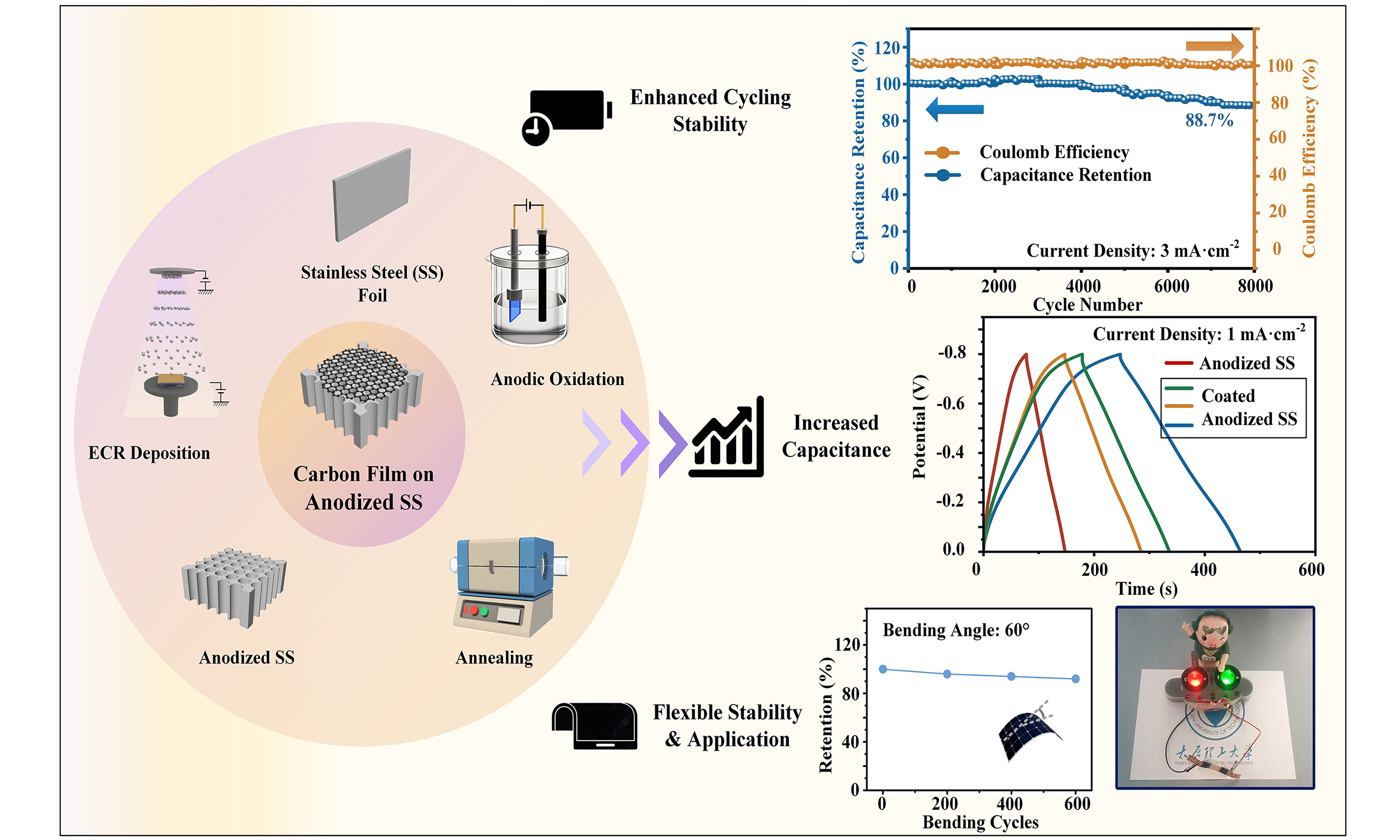
Electrochemically anodized stainless steel (SS) shows promise as a free-standing electrode in flexible supercapacitors due to its low cost, eco-friendly nature, and binder-free characteristics. However, unsatisfactory cycling stability limits its practical use in wearable electronics. Herein, we introduce a conductive carbon film deposited on the surface of the anodized SS electrode as a protective layer via electron cyclotron resonance sputtering. By optimizing the deposition bias voltage and deposition time, the resulting flexible electrode exhibits a specific capacitance of 271.6 mF·cm-2 at a current density of 1 mA·cm-2, representing a 2.24-fold increase over the uncoated counterpart, with 88.7% capacitance retention after 8,000 cycles. The enhanced performance is closely related to the conductivity of the surface coating, which depends on the sp2/sp3 ratio (the relative proportion of graphitic to diamond-like carbon bonding). The carbon film-coated anodized SS electrode is combined with an activated carbon on carbon cloth electrode and a gel electrolyte to produce a flexible supercapacitor. The energy storage device exhibits a wide operating potential window of 1.8 V, a high energy density of 51.70 mWh·cm-3, and a power density of 0.50 W·cm-3, accompanied by robust flexibility and mechanical stability. These findings may pave the way for the development of high-performance, flexible, and cost-effective supercapacitors compatible with large-scale semiconductor device manufacturing.
Keywords
INTRODUCTION
Owing to the rapid development of the Internet of Things (IoT) and artificial intelligence (AI), wearable and portable electronic devices have attracted enormous attention for applications such as energy storage devices and sensors[1-2]. Flexible supercapacitors are particularly promising due to their fast charge-discharge capability, high power density, safe operation, and long cycle life[3]. For high-performance flexible supercapacitors, free-standing electrodes - including conductive substrates combined with active materials in situ or ex situ - are highly preferred, offering advantages such as excellent portability, low volatility, ease of packaging and molding, and high safety[4]. Recently, we reported the fabrication and performance of Electrochemically anodized stainless steel (SS) as a free-standing electrode[5]. Compared with widely reported alternatives such as carbon cloth (CC)[6], cellulose paper[7] and metallic mesh[8], the anodized SS electrode offers advantages including easy preparation, moderate cost, non-toxicity, binder-free characteristics, and a reliable capacitance of up to 100 mF·cm-2. However, due to the large crystal size of ferric oxide, which induces significant volume changes during the charge-discharge process, the anodized SS electrode suffers from poor cycling stability, with retention dropping to 40%[9], severely limiting its practical application.
The most widely used route to enhance the cycling stability of anodized SS electrodes was to increase their conductivity by material modification. Ahmed et al. grew Co3O4 nanowires on an anodized SS substrate using a hydrothermal method. The heterojunction exhibited a specific capacitance of 529.0 F·g-1, with a retention of 76.0% after 1,000 cycles[10]. Feng et al. fabricated nitrogen-doped anodized SS electrodes using an ion implantation method, achieving a specific capacitance of 332.4 mF·cm-2 and retention of 76.7% after 8,000 cycles[11]. Chai et al. reported a vanadium-doped anodized SS free-standing electrode with a capacitance of 320.9 mF·cm-2 and 88.4% capacitance retention after 8,000 cycles[12]. Although significant improvements had been achieved through material modification, methods involving wet processing or costly fabrication were not fully compatible with semiconductor device manufacturing in the electronics industry, particularly for wearable electronics[13].
Considering the drawbacks mentioned above, another possible route was to build a protection layer on the surface of electrodes. Carbon film is one of the most promising candidates due to its stable chemical properties, good mechanical strength, and highly controllable deposition process[14]. Moreover, the combination of a pseudocapacitance material (anodized SS) with a double-layer material (carbon film) could lead to improved capacitance and cycling stability theoretically[15]. Unfortunately, most conventional methods can only deposit amorphous carbon films with relatively low conductivity. As a protective layer, the nearly insulating carbon film could hinder charge transport between the electrode and the electrolyte, resulting in a significant decline in capacitance. In 2011, Wang and Diao reported a carbon film embedded with graphene sheets inside by electron cyclotron resonance (ECR) sputtering[16]. This kind of film exhibits significantly improved conductivity due to a high proportion of sp2 carbon. Beyond the general tribology application and recent uses in photodetectors and electrocatalytic sensors[17,18], the film was expected to be adopted as a protection layer on the surface of the anodized SS flexible electrode.
Herein, to enhance the cycling stability of anodized SS electrodes, a series of carbon films were deposited for protection via ECR sputtering. The electrochemical performance was optimized by adjusting the deposition bias voltage and deposition time. The electrochemical properties, especially the specific capacitance and capacitance retention of the electrodes before and after coating, were emphasized. To clarify the energy storage mechanism, the relationship among the sp2/sp3 ratio, the electrical properties, and the electrochemical properties of carbon film-coated anodized SS electrodes was analyzed and discussed in detail based on the characterization results. Meanwhile, an all-solid-state flexible supercapacitor device based on the carbon film-coated anodized SS electrode was assembled to power small appliances, demonstrating excellent practical performance as a flexible electrode.
EXPERIMENTAL
Materials
All chemicals were used directly without purification or additional treatment. Ethanol (C2H6O, 99.7%), ethylene glycol (EG, C2H6O2, 99.5%) and ammonium fluoride (NH4F, 96.0%) were obtained from Sinopharm Chemical Reagent Co., Ltd. (Shanghai, China). Potassium persulfate (KPS, K2O8S2, 99.9%) and acrylamide (AM, C3H5NO, 99.9%) were purchased from Shanghai Acmec Biochemical Co., Ltd. (Shanghai, China). N,N′-methylenebisacrylamide (MBA, C7H10N2O2, 99.0%), 304 SS foil (0.05 mm thick), silica wafer (4-inch type, 0.525 mm thick) and CC (0.17 mm thick) were acquired from Shanghai Aladdin Biochemical Technology Co., Ltd. (Shanghai, China). Activated carbon (AC, YP80F specific surface area 1,900-
Electrode preparation
The SS foils and silica wafers were cut into 20 mm squares and then subjected to ultrasonic baths in ethanol and deionized (DI) water for 10 min each. The cleaned SS foil was processed using a simple anodic oxidation method described in our previous work[5]. Briefly, the sample was fabricated by an anodization procedure in a two-electrode electrochemical cell, where a SS foil served as the anode, a graphite plate as the cathode, a solution containing 0.3700 g NH4F, 98 mL EG, and 2 mL DI water as the electrolyte. The whole anodization procedure was conducted at 60 V for 2 h with an optimized parameter. After being carefully rinsed in ethanol, the electrodes were annealed at 500 °C for 1 h for stabilization. The as-fabricated electrode was named C-0 in the following characterizations and performance tests.
The carbon film was sputtered through an ECR plasma nano-surface manufacturing device. The anodized SS foil was placed into the chamber of the ECR system, followed by reducing the background vacuum below 5.00 × 10⁻⁴ Pa. As the working gas, dry argon gas was introduced to the chamber until the pressure stabilized at 4.00 × 10⁻² Pa. The plasma was generated by the combined effect of a closed electromagnetic field formed by a microwave (2.45 GHz, 200 W) and double magnetic coils (420 A), with the target bias voltage set at
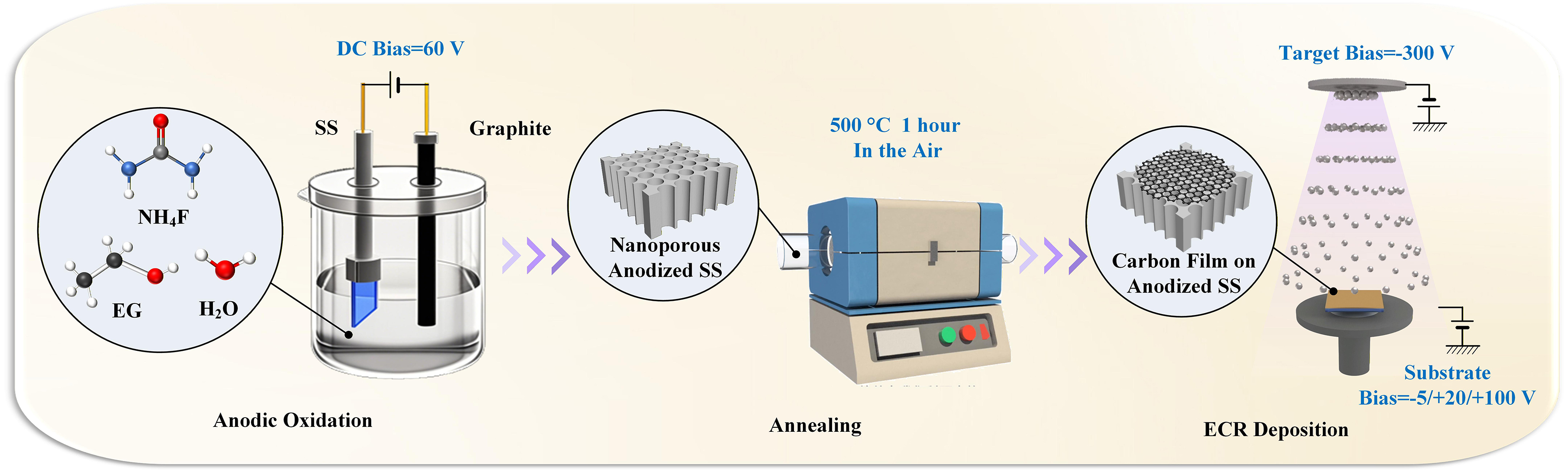
Figure 1. Schematic diagram of the fabrication process of anodized SS flexible electrodes coated with ECR carbon film. SS: Stainless steel; ECR: electron cyclotron resonance; EG: ethylene glycol; DC: direct current.
All-solid-state flexible supercapacitor assembly
To explore its potential for flexible energy storage, an all-solid-state supercapacitor was constructed using a combination of a CC anode coated with AC (AC@CC, 15 × 10 × 0.17 mm, 0.0693 g), a carbon film-coated anodized SS cathode (15 × 10 × 0.05 mm, 0.0856 g), and a polyacrylamide (PAM)/Na2SO4 gel electrolyte (15 × 10 × 1 mm in size, 0.3691 g). The total weight of the flexible supercapacitor was 3.9274 g, including the polyethylene terephthalate seal and copper tape.
The gel electrolyte was used to assemble the all-solid-state flexible supercapacitor. A total of 2.1324 g of AM and 0.0040 g of MBA were uniformly dispersed in 10 mL of DI water, followed by the addition of 0.0400 g of KPS with continuous stirring. The mixture was shaped in a mold and then placed in an oven (Kaile DZF6020, China) at 60 °C for 6 h to obtain the PAM gel. The as-fabricated gel was subsequently immersed in 1 M Na2SO4 for 24 h to produce the PAM/Na2SO4 gel electrolyte.
Physicochemical characterization
A scanning electron microscope (SEM, Zeiss GeminiSEM 300, Germany), a transmission electron microscope (TEM, Thermo Fisher Talos F200S G2, USA), and an energy dispersive X-ray spectrometer (EDS, Zeiss GeminiSEM 300, Germany) were used to observe the surface morphology and element distribution of the carbon film-coated nanoporous structure. X-ray diffraction (XRD, PANalytical Empyrean, Netherlands) was employed to determine the crystal phases of the anodized SS sample under Cu-Kα irradiation over a scan range of 20°-70°. The elemental compositions were analyzed using X-ray photoelectron spectroscopy (XPS, Thermo Fisher K-Alpha, USA).
To avoid the influence of the SS substrate, a series of carbon films on silica wafer samples were deposited, and their thicknesses were measured by a stylus profiler (Bruker DektakXT, USA), followed by the resistivity obtained via a four-probe method (4Probes Tech RTS-8, China). The Raman spectra (Horiba LabRAM HR Evolution, Japan) were analyzed under a 532 nm wavelength laser ranging from 1,000 to 3,500 cm-1.
Electrochemical measurements
The electrochemical characterizations, including cyclic voltammetry (CV), galvanostatic charge-discharge (GCD), electrochemical impedance spectroscopy (EIS), and cycling test, were performed on an electrochemical workstation (Zahner IM6, Germany). The intrinsic capacitance of the electrode was studied using a three-electrode system, where the as-fabricated electrodes served as the working electrode, a platinum mesh as the counter electrode, a standard Ag/AgCl electrode as the reference electrode and 1 M Na2SO4 as the electrolyte. The electrochemical performance of the flexible supercapacitor was evaluated in a two-electrode system mentioned above. The specific capacitance (C), energy density (E), and power density (P) were calculated using[19]:
where I represents the discharge current, t is the discharge time, ΔV is the potential window, and S is the active area.
RESULTS AND DISCUSSION
Morphological and structural characterization
Figure 2A and B illustrates SEM micrographs of the SS substrate before and after the anodic oxidation process. The initially smooth SS surface became porous, with pore radii of approximately 40 nm, which can be attributed to the steady-state competition between the oxidation of Fe, Cr, and Ni in the SS substrate and the etching of the resulting metal oxides[20]. Figure 2C-E presents the carbon film deposition result with the bias voltage of -5, +20 and +100 V for 10 min, respectively. The entire surface and sidewalls were coated with one homogeneous film successfully, making the pores much narrower than before. Since the nanoporous structure was neither perfectly tubular nor flat on the top surface, the coated film appeared as particles with sizes on the order of tens of nanometers. As shown in Supplementary Figure 1, the thicknesses of the carbon films coated under -5, +20, and +100 V were 60, 45, and 40 nm, respectively, consistent with the observed morphology of the samples. Supplementary Figure 2 presents the surface of +100 V-coated electrodes with different deposition times. It can be clearly observed that the sidewalls of the nanoporous structure thickened, and when the deposition time exceeded 20 min, the top surface was fully covered by the carbon film. Figure 2F shows the TEM result of the C-3 sample, where a tubular structure with a radius of 38 nm is clearly visible. A dark layer attached to the sidewall of the tubular structure, which was not observed in our previous anodized SS reports[5,11-12], can be considered as the coated carbon film. In the high-resolution image in Figure 2G, the major lattice spacings of 0.250 and 0.369 nm can be indexed to the (110) and (012) crystal planes of Fe2O3, respectively. Several bowed and discontinuous lattices are observed in the dark region, interpreted as stacks of graphene sheets within the amorphous carbon matrix. These graphene sheets may contribute to the decreased electrical resistance of the carbon film and become visible at irradiation energies above 40 eV, as reported by Wang and Diao[16]. Supplementary Figure 3 displays the EDS spectrum of the C-3 sample, where the elements Fe, Ni, Mn, Cr, and O are attributed to the oxidized SS foil, and C originates from both the carbon film coating and the SS substrate. Figure 2H-K shows the uniform distribution of the three major elements: C, O, and Fe.
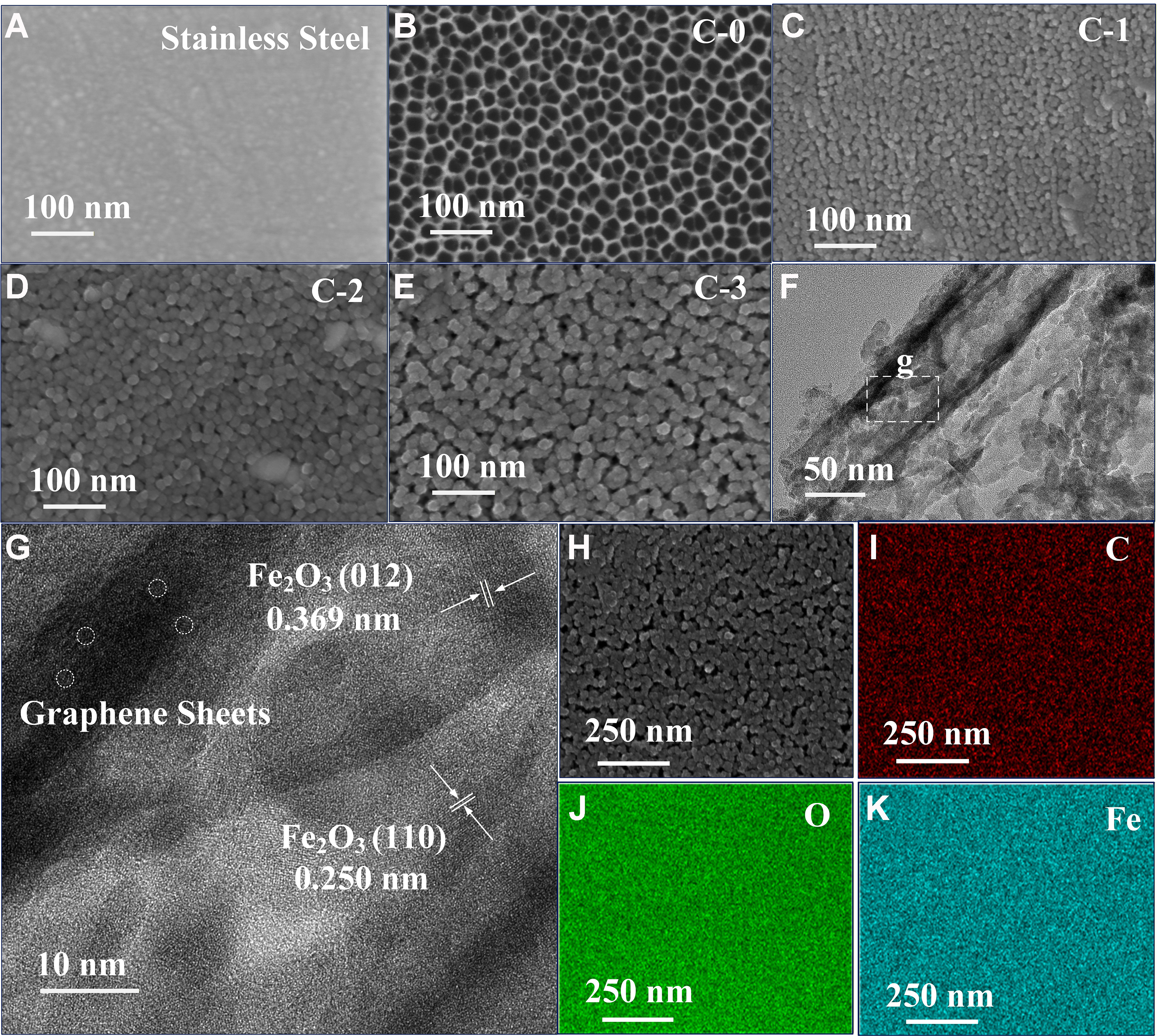
Figure 2. FESEM images of (A) SS substrate, (B) C-0, (C) C-1, (D) C-2, and (E) C-3; (F and G) HRTEM images of C-3; EDS elemental mapping of C-3: (H) HAADF image, (I) C, (J) O, and (K) Fe. FESEM: Field emission scanning electron microscope; SS: stainless steel; HRTEM: high-resolution transmission electron microscopy; EDS: energy dispersive X-ray spectrometer; HAADF: high-angle annular dark-field.
Figure 3A shows the XRD spectrum of the C-3 sample. The characteristic peaks at 24.3°, 33.4°, 36.0°, 41.3°, 50.0°, and 54.6° are attributed to the (012), (104), (110), (113), (024), and (116) planes of Fe2O3 (Joint Committee on Powder Diffraction Standards, JCPDS No. 84-0311), respectively. The peaks at 30.0°, 35.3°, 57.2°, and 62.8° correspond to the (220), (311), (511), and (440) planes of Fe3O4 (JCPDS No.88-0351), respectively. The peak at 44.3° is assigned to the unevenly distributed martensite within the SS foils[21]. No obvious peak corresponding to graphitic carbon was observed in the spectrum, which can be attributed to the relatively low content of graphene sheets in the carbon film, as confirmed by TEM observations. The XPS spectra of the fabricated electrodes are shown in Figure 3B-E. Consistent with the EDS results, the survey spectrum of C-3 [Figure 3B] clearly confirms the presence of C, O, Cr, and Fe, indicating successful carbon film deposition. Figure 3C shows the C 1s peak, which can be deconvoluted into four Gaussian components at approximately 284.6, 285.2, 286.6, and 288.8 eV, corresponding to C=C (sp2 phase), C–C (sp3 phase), C–O bonds, and a combination of C=O and O–C=O bonds, respectively[22,23]. From the analytical data in Table 1, it can be concluded that with the increase of deposition bias voltage from -5 to +100 V, the sp2 content increased, leading to higher conductivity of the C-3 electrode compared to C-2 and C-1. This result is consistent with the work by Wang and Diao and can be explained by the damage to graphene sheets in the carbon film under negative substrate bias voltage and the structural transition from amorphous carbon to graphene sheets under electron irradiation at positive substrate bias voltage[16]. The O 1s peaks of C-0 and C-3 samples are analyzed in Figure 3D and Table 1. Both spectra can be fitted with two peaks at 530.5 and 532.1 eV, corresponding to crystal oxygen and adsorbed oxygen, respectively[24]. Since O2 is the most common reactive gas in contact with carbon films, the amount of adsorbed oxygen in coated electrodes is significantly higher than in the uncoated sample[25]. It was reported that adsorbed oxygen can provide unsaturated oxygen coordination, thereby enhancing the electrochemical performance[26,27]; thus, C-1, C-2, and C-3 electrodes could benefit from carbon film deposition. The slightly lower adsorbed oxygen in C-3 compared to C-2 and C-1 may be attributed to the lower adsorption energy of molecular oxygen on sp2 carbon[28]. Figure 3E shows the Fe 2p spectrum of electrode C-3. The peaks at 710.8 eV (Fe 2p3/2) and
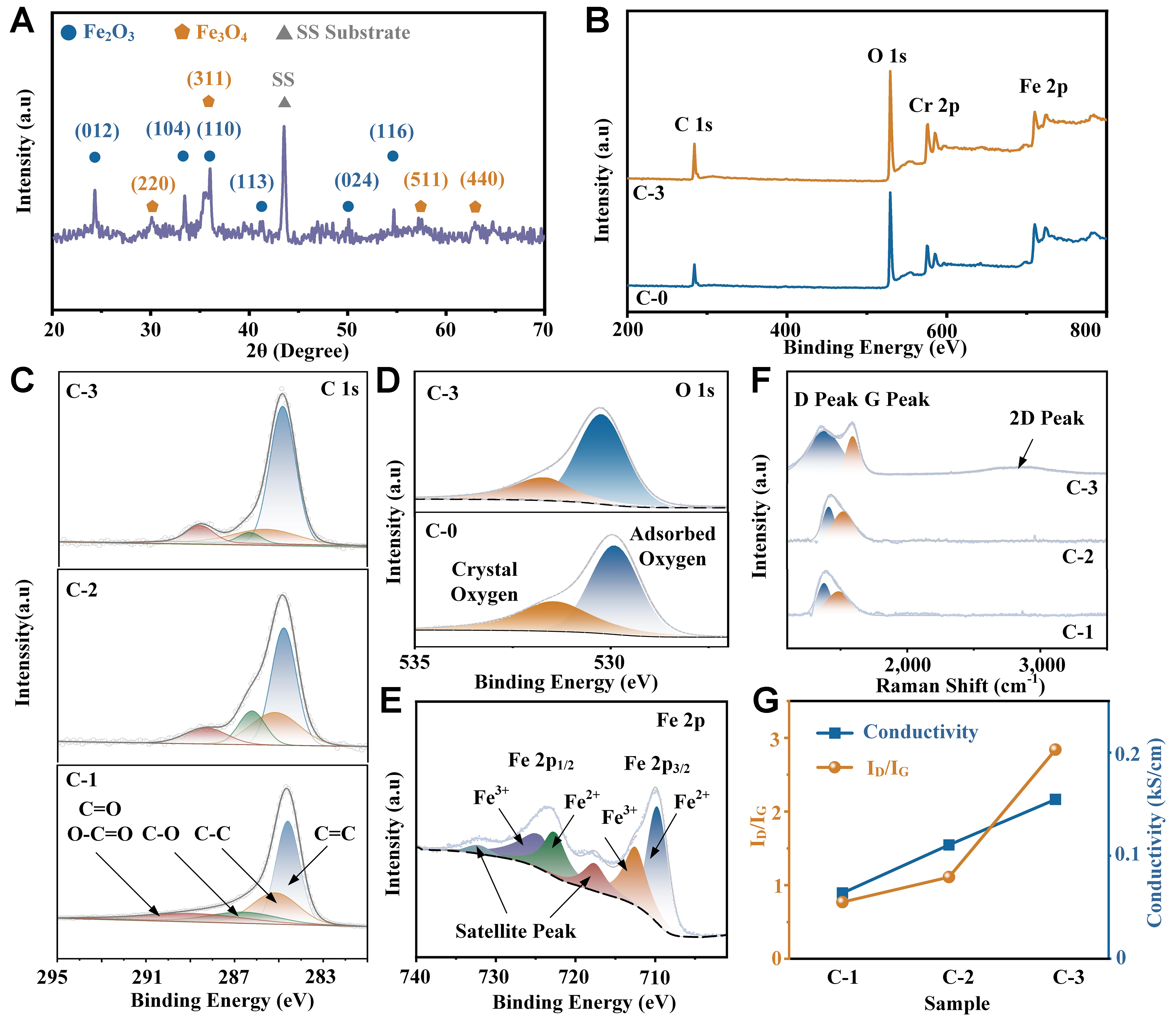
Figure 3. (A) XRD pattern of C-3; (B) XPS survey of the C-0 and C-3; (C) C 1s XPS spectra of C-1, C-2 and C-3; (D) O 1s XPS spectra of C-0 and C-3; (E) Fe 2p XPS spectra of C-3; (F) Raman pattern of C-1, C-2 and C-3; (G) Comparison of ID/IG and conductivity. XRD: X-ray diffraction; XPS: X-ray photoelectron spectroscopy; SS: stainless steel.
XPS analysis results of C-0 (uncoated), C-1, C-2, and C-3 electrodes
| C=C | C–C | C–O | C=O and O–C=O | Adsorbed oxygen | Crystal oxygen | |
| C-3 | 0.63 | 0.17 | 0.09 | 0.11 | 0.66 | 0.34 |
| C-2 | 0.48 | 0.26 | 0.11 | 0.15 | 0.68 | 0.32 |
| C-1 | 0.46 | 0.27 | 0.14 | 0.13 | 0.71 | 0.19 |
| C-0 | - | - | - | 0.50 | 0.50 |
The resistivity of the three carbon films was measured using a four-probe method on samples deposited on silica wafers, yielding 15.67, 9.06, and 6.47 mΩ·cm for C-1, C-2, and C-3, respectively. Figure 3G compares the ratio of D and G band intensities (ID/IG) with the corresponding conductivity of the carbon-coated samples. Since the ID/IG value is inversely related to the sp2 fraction[34], C-1 exhibited the highest resistivity, followed by C-2, with C-3 showing the lowest, consistent with the TEM and XPS results. This observation aligns with the elemental composition analysis described above: the sp2 fraction increased with increasing substrate bias voltage from -5 V (C-1) to +20 V (C-2) and +100 V (C-3), resulting in reduced resistivity[35].
Electrochemical performance
The effect of carbon film deposition parameters, including substrate bias and deposition time, on the supercapacitor performance of the composite electrode materials was investigated using a three-electrode system with 1 M Na2SO4 electrolyte. Figure 4A shows the CV curves of the uncoated electrode C-0 and the coated electrodes C-1, C-2, and C-3, prepared under different substrate bias voltages, with a voltage window of -0.8 to 0.0 V and a scan rate of 100 mV·s-1. All these curves displayed semi-rectangular shapes with no characteristic redox peaks observed, which was widely reported for Na2SO4 electrolyte, demonstrating the outstanding pseudocapacitive behavior[36]. Moreover, it was observed that the enclosed area and current response of the CV curves were directly proportional to the storage capacitance of the materials[37]. Thus, the carbon film-coated electrodes could have the largest capacitance evidently, and among them, C-3 electrode performed the best. The detailed capacitance was calculated based on the GCD curves [Figure 4B] and Equation (1). At a current density of 1 mA·cm-2, the capacitance of C-1, C-2 and C-3 electrodes was 161.5, 178.5 and 271.6 mF·cm-2, respectively, much larger than that of the uncoated electrode (121.1 mF·cm-2), and increased with increasing deposition bias voltage. In addition, owing to the binder-free anodization method, the internal resistance drops (IR-drops) of the four electrodes were below 0.05 V, reflecting a highly effective charge transfer between active material and SS foil collector[38]. Figure 4C shows the capacitance of all electrodes at different current densities. The results indicate that the capacitance decreased with increasing current density, while the relative order of the electrodes remained unchanged. Importantly, the coated electrodes exhibited significantly improved initial capacitance retention: only 6.7% for the pristine sample C-0, compared with 23.9%, 27.0%, and 51.8% for C-1, C-2, and C-3, respectively, as the current density increased from 0.5 to 10 mA·cm-2. To understand the reaction kinetics of CV curves for the four electrodes, the diffusion coefficient was calculated using[39]:
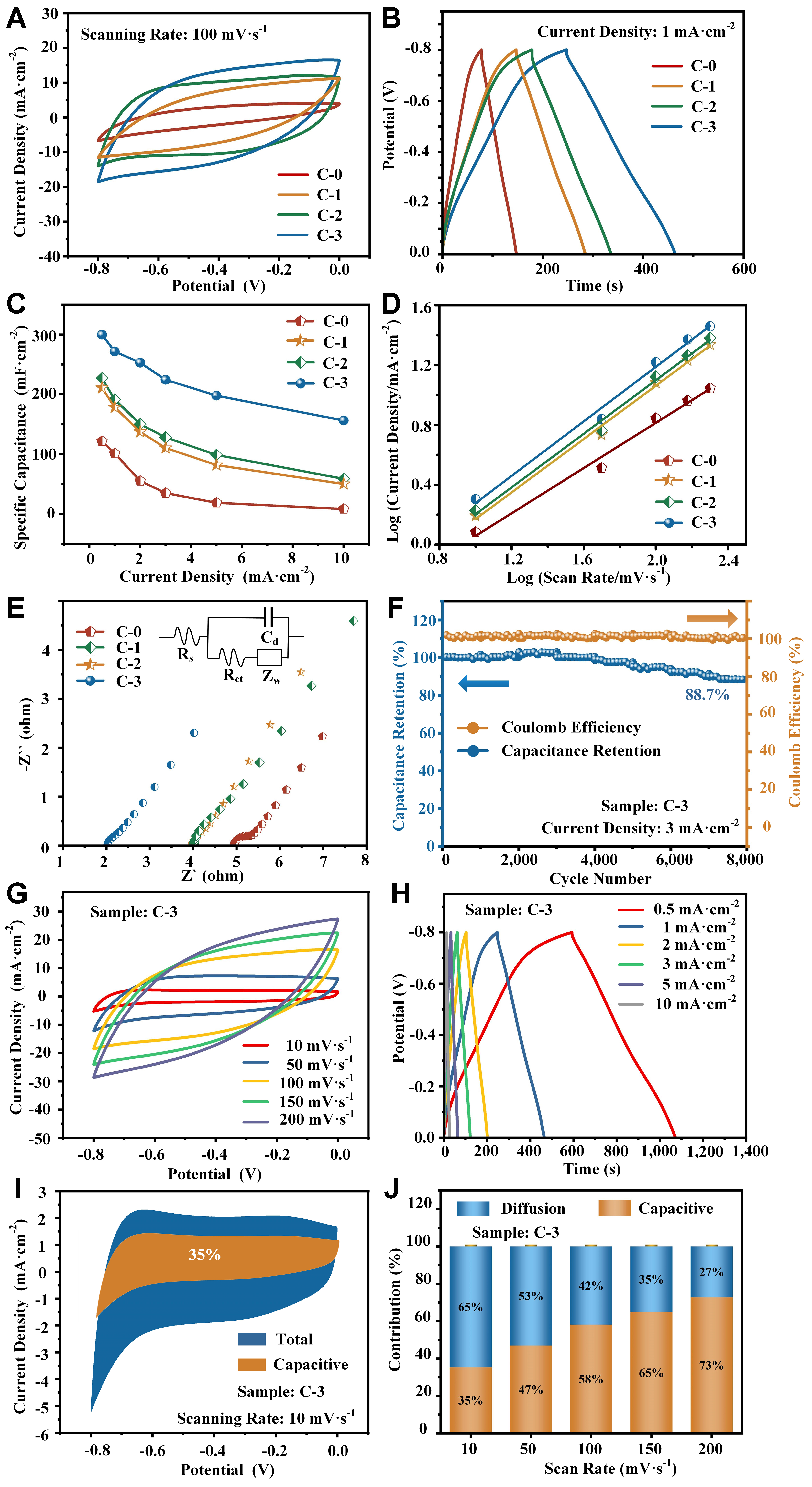
Figure 4. Electrochemical characteristics on C-0, C-1, C-2, and C-3 electrodes in a three-electrode system: (A) CV curves at a scan rate of 100 mV·s-1; (B) GCD curves at a current density of 1 mA·cm-2; (C) Specific capacitance at different scan rates; (D) Linear fitting curves for diffusion coefficient; (E) Nyquist plots and equivalent circuit fitting; Electrochemical characteristics of C-3 electrode: (F) Coulombic efficiency and cycling performance; (G) CV curves at various scan rates; (H) GCD curves at different current densities; (I) Capacitive and diffusion-controlled contributions to charge storage at 10 mV·s-1 from CV curves; (J) Histogram showing the percentage contribution at different scan rates. CV: Cyclic voltammetry; GCD: galvanostatic charge-discharge.
where i is the peak current, v is the scan rate, b represents the diffusion coefficient and a is a constant. A b value of 0.5 indicated the diffusion-controlled process, while the value of 1 demonstrated a surface-controlled process.
The calculation results shown in Figure 4D indicated diffusion coefficients of 0.76, 0.87, 0.88, and 0.91 for C-0, C-1, C-2, and C-3 electrodes, which could be attributed to a surface-controlled dominant process combined with a diffusion-controlled process. The coated electrodes exhibited a significantly higher diffusion coefficient compared with the uncoated electrode, indicating faster charge transfer at the electrode surfaces and superior capacitive behavior due to the increased surface conductivity[40]. To explore the relationship between electrochemical performance and electrode resistance, EIS tests were conducted over a frequency range of 100 kHz to 0.01 Hz. The Nyquist plots are shown in Figure 4E with the equivalent circuit model inset, and the corresponding parameters are listed in Table 2. The interception of the curves with the real axis represents the series resistance (Rs) of the electrodes, with the coated samples exhibiting much lower values that decreased with increasing substrate bias. These results indicate that the carbon film coating effectively reduced the internal resistance, in good agreement with the four-probe measurement data. The radius of the semicircle in the mid-frequency region represents the charge transfer resistance (Rct), which decreased by nearly 25% after carbon film deposition, due to faster charge transfer between the electrode surface and electrolyte facilitated by the carbon network[41]. The Rct values of C-1 and C-2 were quite similar, while that of the C-3 electrode decreased slightly, which can be explained by two factors. First, owing to the binder-free characteristic of anodized SS, the Rct values of all coated electrodes remained low, ranging from 0.42 to 0.47 Ω[42], and the difference in Rct was minimal. Secondly, as confirmed by TEM and Raman characterizations, the presence of graphene sheets inside the C-3 electrode could be regarded as shortcuts that accelerated charge transfer between the electrode and electrolyte, resulting in a lower resistance for the C-3 electrode. In summary, the C-3 electrode exhibited the lowest equivalent internal resistance and the highest electrical conductivity, leading to the best electrochemical performance[43]. Supplementary Figure 4 and Figure 4F compared the coulombic efficiency and capacitance retention of the C-1, C-2, and C-3 electrodes at a current density of 3 mA·cm-2. The experimental results showed that all three electrodes maintained a coulombic efficiency of 100%, while the capacitance retentions after 8,000 GCD cycles were 81.4%, 82.3%, and 88.7%, respectively, showing a slight improvement with decreasing electrode resistance.
Fitting parameters of the equivalent circuit for C-0 (uncoated), C-1, C-2, and C-3 electrodes obtained from EIS measurements
| C-0 | C-1 | C-2 | C-3 | |
| Rs | 4.89 Ω | 3.98 Ω | 3.94 Ω | 2.08 Ω |
| Rct | 0.62 Ω | 0.47 Ω | 0.47 Ω | 0.42 Ω |
Supplementary Figure 5 demonstrated the effect of deposition time on the electrochemical performance of the optimized +100 V substrate bias coated electrode, varying from 0 min (uncoated, C-0), 5 min, 10 min (C-3), and 20 min. It was found that 10 min was the optimum deposition time, as further confirmed by the lowest Rs and Rct values [Supplementary Table 1], reflecting a combination of high conductivity and efficient charge transfer kinetics[4]. This could be interpreted as follows: under short deposition time, the nanoporous structure on the SS foil was not fully covered by the carbon film, especially at the sidewalls, resulting in relatively high electrode resistance; under long deposition time, the over-thick carbon film blocked the nanopores, leading to inefficient charge transfer between the electrode and electrolyte. This explanation was partly supported by SEM and TEM observations.
Figure 4G and H shows the CV and GCD results of the optimized C-3 electrode at different scan rates and current densities. With increasing scan rates, the area of the CV curves increased, while the charge-discharge time decreased at higher current densities. No significant changes were observed in the shapes of the CV and GCD curves, indicating low resistance, good structural stability, and reversibility of the electrodes[44]. In a neutral Na2SO4 electrolyte, the redox reaction of the C-3 electrode could originate from Na+-induced surface electron transfer involving ferric oxide, as follows[45]:
The specific contributions of the total capacitance from capacitive and diffusion-controlled processes were calculated using a modified Power-law model as follows[46]:
where i(V) is the total current under a fixed potential V, v denotes the scan rate, and k1 and k2 represent the constants of the capacitive and diffusion process. Figure 4I shows the capacitance contribution of the C-3 electrode at 10 mV·s-1 in brown, and the detailed contribution proportions at various scan rates are summarized in Figure 4J. As the scan rate increased from 10, 50, 100, 150 to 200 mV·s-1, the corresponding capacitance contribution ratios increased to 35%, 47%, 58%, 65%, and 73%, respectively. This phenomenon can be attributed to the fact that at higher scan rates, the charge storage and release processes are accelerated, making the capacitive-controlled process more dominant, while the diffusion-controlled process becomes limited. Moreover, the carbon film coating enhanced the material’s electrical conductivity, thereby promoting rapid storage of capacitive charges[11]. The relatively high contribution ratio indicates that the C-3 electrode can withstand higher current densities, demonstrating superior rate capability. Supplementary Figure 6 displays the CV, GCD, cycling stability, and capacitance contribution curves of the uncoated C-0 electrode for comparison. As mentioned earlier, the C-3 electrode exhibited a 2.24-fold increase in areal capacitance compared with C-0 at a current density of 1 mA·cm-2. A 48.9% improvement in capacitance retention after 8,000 cycles was achieved through surface carbon film deposition. Since the retention values of C-1, C-2, and C-3 were nearly the same, this enhancement may be related to the stabilization effect of the carbon film on the fragile sidewalls of the anodized nanoporous structure. To further confirm this, the surface morphology of the C-3 electrode after 8,000 GCD cycles was observed by SEM. No obvious breakage was found when comparing Figure 2E and Supplementary Figure 2D, demonstrating the protective effect of the carbon film. In addition, the proportion of capacitive contribution for C-3 was much higher than that of the pristine C-0 electrode, which can be attributed to carbon film-induced resistance reduction, leading to faster charge transfer at the electrode surface and superior capacitive behavior[47].
As a result, both the capacitance and cycling stability of the anodized SS flexible electrode were significantly enhanced by a 50 nm-thick ECR carbon film coating. The underlying mechanism can be summarized as follows. Regarding capacitance improvement, the ECR carbon film exhibits much higher conductivity than Fe2O3 or Fe3O4, enabling efficient electronic transport during charging and discharging, which facilitates rapid redox reactions and effective utilization of the entire electrode[48]. Moreover, the ECR carbon film contains abundant surface hydroxyl and carboxyl groups, enhancing hydrophilicity and providing additional redox-active sites, which promote the migration of electrolyte ions into the electrode and contribute to higher specific capacitance[49,50]. In terms of cycling stability, the carbon film covers the anodized SS surface, mitigating volumetric changes of Fe2O3 and Fe3O4 during charge-discharge cycles. This protection reduces active material loss due to dissolution or detachment, thereby improving capacitance retention[51].
Table 3 summarizes the electrochemical performance of other ferric oxide-based electrodes. While these electrodes exhibited high specific capacitance, their cycle life retention was limited. Our ECR carbon film coating approach addresses this limitation by preserving capacitance, making it a promising strategy for commercial applications due to its high processing compatibility.
Electrochemical performance of C-3 and other SS-based electrodes evaluated in a three-electrode system
| Electrode materials | Substrate | Electrolyte | Current density | Specific capacitance | Cycle life retention | Ref. |
| N-doped oxidized SS | SS foil | 1 M Na2SO4 | 1.0 mA·cm-2 | 321.3 mF·cm-2 | 500%-70.0% | [5] |
| N-doped oxidized SS | SS foil | 1 M Na2SO4 | 1.0 mA·cm-2 | 332.3 mF·cm-2 | 8,000%-76.6% | [11] |
| Phosphate modified Fe2O3 nanoparticles | CC | 6 M KOH | 5.0 mV·s-1 | 520.0 F·g-1 | 10,000%-80.1% | [52] |
| Fe2O3 nanowire | Conductive carbon fabric | 1 M Na2SO4 | 1.0 mA·cm-2 | 215.0 mF·cm-2 | N/A | [53] |
| Fe2O3 nanocube | Graphite sheet | 3 M KOH | 2.0 A/g | 908.0 F·g-1 | 1,000%-65.0% | [54] |
| Fe2O3 nanoparticle | Nitrogen-doped wood carbons | 3 M KOH | 0.1 A/g | 603.0 F·g-1 | 10,000%-85.5% | [55] |
| Fe2O3 octahedron | Glassy carbon | 6 M KOH | 0.5 A/g | 274.0 F·g-1 | 5,000%-83.0% | [56] |
| Carbon film coated oxidized SS (C-3) | SS foil | 1 M Na2SO4 | 1.0 mA·cm-2 (1.9 A/g) | 271.6 mF·cm-2 (512.5 F/g) | 8,000%-88.7% | This work |
Performances of flexible supercapacitor based on carbon film-coated nanoporous structure
The carbon film-coated nanoporous structure on SS substrate was considered to have broad commercial potential as a flexible supercapacitor electrode. As a step toward practical application, an all-solid-state flexible supercapacitor was assembled using the optimized C-3 electrodes. CV tests were performed on the device to determine a suitable voltage window, with applied voltages ranging from 1.2 to 2.0 V. As shown in Figure 5A, the CV curves expanded steadily as the voltage increased up to 1.8 V. However, the maximum current density rose sharply from 17.5 to 27.5 mA·cm-2 near 2.0 V, producing a “tail” at the edge of the CV curve[57]. This behavior is characteristic of polarization, caused by parasitic side reactions such as electrolyte or electrode material decomposition[58]. Therefore, the optimized voltage window of the flexible supercapacitor was set at 1.8 V, consistent with the theoretical potential windows of the C-3 electrode (-0.8~0.0 V) and AC@CC electrode (0.0-1.0 V)[12]. Figure 5B and C presents the CV and GCD results of the flexible supercapacitor at various scan rates and current densities. Similar to the three-electrode tests, the quasi-rectangular CV curves and triangular GCD curves were maintained, confirming the highly reversible capacitive behavior. From the GCD curves, a specific capacitance of 101.50 mF·cm-2 was obtained at a current density of 1.0 mA·cm-2, with a minimal IR-drop. The capacitance retention and Coulombic efficiency are shown in Figure 5D. After 8,000 GCD cycles at 3 mA·cm-2, the capacitance retention was 79.2%, while Coulombic efficiency remained at 100%. The EIS curves before and after 8,000 cycles [Figure 5E] indicated increases of 1.12 and 0.08 Ω in Rs and Rct, respectively, demonstrating good cycling stability and reversibility. The capacitance retention was slightly lower than that observed in the three-electrode tests, similar to our previous study using the same AC@CC anode[12]. This suggests that the retention may be limited by the anode and could be further improved in future work. The energy density (E) and power density (P) of the flexible supercapacitor were calculated using Equations (2) and (3). As shown in the Ragone plot [Figure 5F], at power densities of 0.50, 1.00, 2.00, 3.24, 5.80, and 13.40 W·cm-3, the corresponding energy densities were 51.70, 50.21, 44.63, 39.49, 29.72, and 11.87 mWh·cm-3, respectively. The assembled all-solid-state flexible supercapacitor outperformed many recently reported flexible energy storage devices based on carbon or metal oxides over the past three years[59-66].
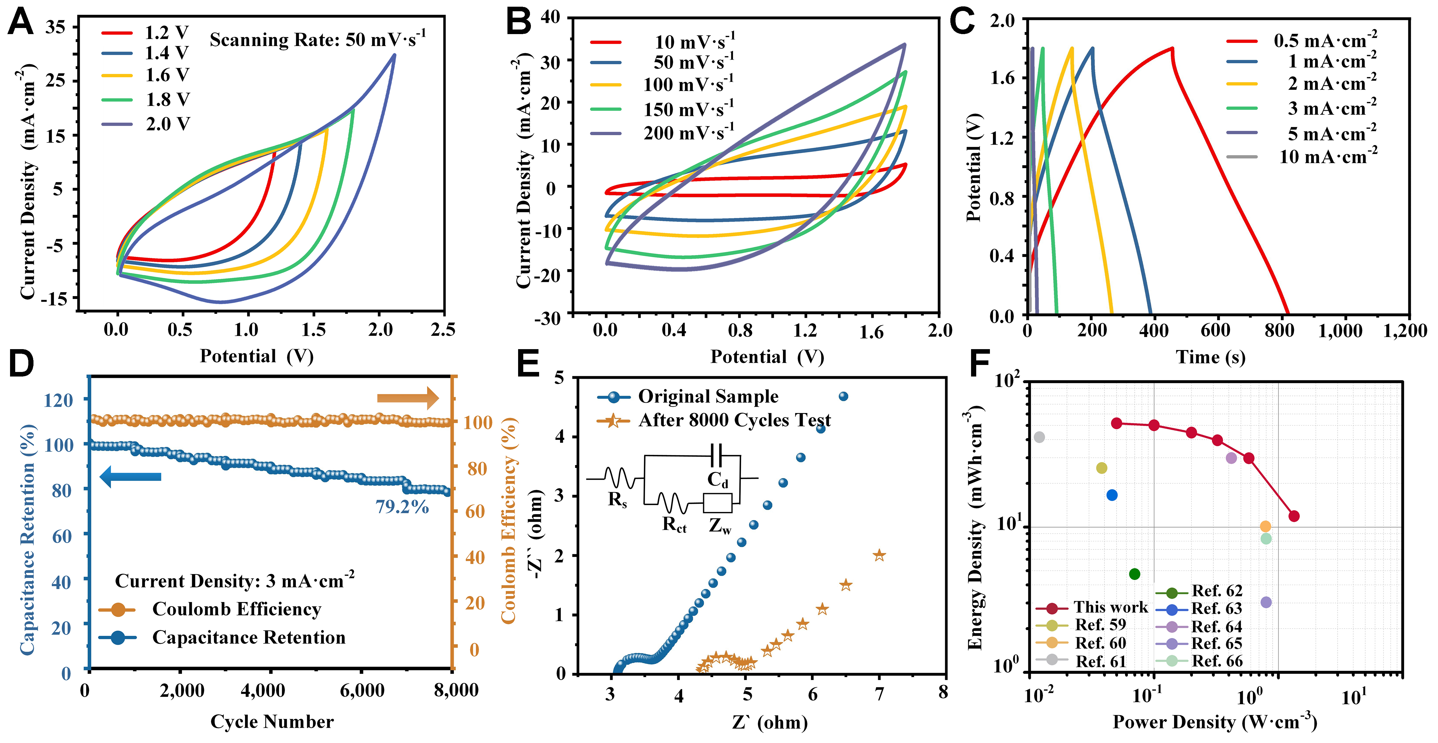
Figure 5. Electrochemical characteristics of the flexible supercapacitor based on the C-3 electrode: (A) CV curves at various applied voltages for optimization of the voltage window; (B) CV curves at different scan rates; (C) GCD curves at different current densities; (D) Coulombic efficiency and cycling performance; (E) Nyquist plots and fitting curves before and after 8,000 GCD cycles; (F) Ragone plot. CV: Cyclic voltammetry; GCD: galvanostatic charge-discharge.
Figure 6 exhibits the practical applications of the flexible supercapacitor based on the carbon film-coated oxidized SS electrode. The flexibility was evaluated through manual bending at different angles and cycles, calibrated using a commercial inclinometer (Syatek SYLF5, China). The procedure included repeated bending and recovery processes, with the bending angle defined in the inset of Figure 6A. The performance was assessed from the GCD curves at a current density of 1 mA·cm-2[67]. As shown in Figure 6A and B, nearly 90% of the capacitance was retained after 600 bending cycles at an angle of 60°, with no significant change in the shape of the corresponding GCD curves. In addition, as the bending angle increased from 60° to 180°, the GCD curves remained stable [Figure 6C]. These results confirm the mechanical flexibility and stability of the supercapacitor for applications in electronic devices and medical equipment that require various curvatures[68]. Figure 6D and E further illustrates practical demonstrations of the flexible supercapacitor, including powering a multifunctional timer and a baby’s toy. The discharge process and detailed operating time are provided in the Supplementary Video. The supercapacitors reported here show strong potential for use in flexible electronics, such as power supplies for gas sensors[69] or energy storage units for nanogenerators[70].
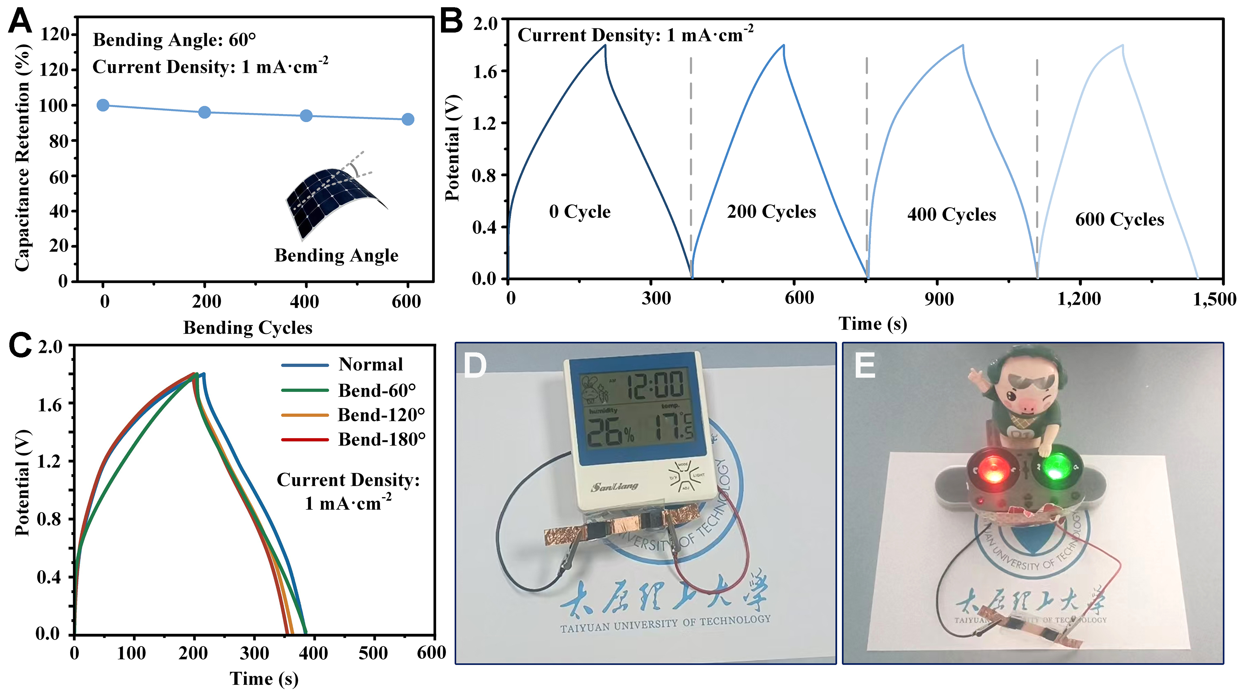
Figure 6. Practical applications of the flexible supercapacitor based on the C-3 electrode: (A) Bending fatigue test; (B) corresponding GCD curves under different bending cycles; (C) GCD curves under different bending angles; (D) powering a multifunctional timer; (E) powering a baby’s toy. GCD: Galvanostatic charge-discharge.
CONCLUSION
To enhance the cycling stability of Electrochemically anodized SS as a free-standing electrode for flexible supercapacitor applications, a carbon film was successfully deposited on its surface via ECR sputtering. The results showed that the carbon film-coated electrode achieved an areal capacitance of 271.6 mF·cm-2, representing a 2.24-fold improvement over the uncoated electrode. More importantly, the capacitance retention increased to 88.7% after 8,000 GCD cycles under the optimized conditions of a +100 V bias voltage and a deposition time of 10 min. This enhancement was attributed to the increased deposition bias voltage, which led to a higher sp2/sp3 ratio and lower electrode resistivity, as confirmed by XPS, Raman spectroscopy, and four-probe measurements. This work elucidates the structure-activity relationship between the carbon coating and capacitive behavior and provides a viable strategy for fabricating high-performance two-dimensional or flexible energy storage devices.
DECLARATIONS
Authors’ contributions
Methodology, formal analysis, investigation, data curation, visualization, and writing - original draft: Zhang, W.; Liu, Z.; Liu, J.; Chai, C.; Xue, P.
Conceptualization, supervision, project administration, writing - review and editing: Li, G.; Yuan, Z.; Yang, L.
Availability of data and materials
All data are available in the main text, the Supplementary Materials or the Supplementary Video. Further information can be obtained from the corresponding authors upon reasonable request.
AI and AI-assisted tools statement
Not applicable.
Financial support and sponsorship
This work was supported by the National Natural Science Foundation of China (52275568, 52005363) and the Fundamental Research Program of Shanxi Province (202403021221056).
Conflicts of interest
All authors declared that there are no conflicts of interest.
Ethical approval and consent to participate
Not applicable.
Consent for publication
Not applicable.
Copyright
© The Author(s) 2026.
Supplementary Materials
REFERENCES
1. Yang, X.; Jin, X.; Feng, H.; et al. Carbon-modified NiCo2O4 as an electrode material for supercapacitors. J. Phys. Chem. Solids. 2024, 193, 112208.
2. Chen, Y.; Zhang, X.; Lu, C. Flexible piezoelectric materials and strain sensors for wearable electronics and artificial intelligence applications. Chem. Sci. 2024, 15, 16436-66.
3. Wang, Q.; Ma, Y.; Liang, X.; Zhang, D.; Miao, M. Flexible supercapacitors based on carbon nanotube-MnO2 nanocomposite film electrode. Chem. Eng. J. 2019, 371, 145-53.
4. Song, W.; Wang, K.; Lian, X.; Zheng, F.; Niu, H. Non-preoxidation synthesis of MXene integrated flexible carbon film for supercapacitors. Chem. Eng. J. 2024, 493, 152804.
5. Zhang, W.; Xu, J.; Li, G.; Wang, K. Nitrogen-doped nanoporous anodic stainless steel foils towards flexible supercapacitors. Materials 2022, 15, 1615.
6. Li, S.; Zhao, M.; Peng, C.; Xiao, Y.; Yu, S. Binder-free carbon nanofiber@carbon cloth for supercapacitor and Li-ion capacitor. Appl. Surf. Sci. 2025, 685, 161990.
7. Xiong, C.; Wang, T.; Han, J.; Zhang, Z.; Ni, Y. Recent research progress of paper‐based supercapacitors based on cellulose. Energy. Environ. Mater. 2023, 7, e12651.
8. Kumar, R.; Ranjan, B.; Kumar, K.; Shankhdhar, S.; Kaur, D. Ti–Cr–N nanopyramid/nitrogen-doped carbon quantum dot/stainless steel mesh as a flexible supercapacitor electrode. ACS. Appl. Nano. Mater. 2024, 7, 7663-73.
9. Zhu, Y.; Cheng, S.; Zhou, W.; et al. Construction and performance characterization of α-Fe2O3/rGO composite for long-cycling-life supercapacitor anode. ACS. Sustainable. Chem. Eng. 2017, 5, 5067-74.
10. Ahmed, I. B.; Diaby, M.; Nafati, H.; et al. Supercapacitive performance of 3D-cobalt oxide (Co3O4) nanowires grown onto anodized stainless-steel substrate: effect of anodization time. Solid. State. Sci. 2024, 152, 107537.
11. Feng, T.; Luo, X.; Liu, Z.; et al. Nanoarchitectonics of highly flexible iron-oxide nanoporous electrodes on stainless steel substrate for wearable supercapacitors. Appl. Phys. Rev. 2024, 11, 041414.
12. Chai, C.; Feng, T.; Liu, Z.; et al. Vanadium-doped nanoporous structure on stainless steel substrate for high-performance flexible supercapacitor. J. Power. Sources. 2025, 628, 235933.
13. Huang, P.; Lethien, C.; Pinaud, S.; et al. On-chip and freestanding elastic carbon films for micro-supercapacitors. Science 2016, 351, 691-5.
14. Pauleau, Y.; Thièry, F. Deposition and characterization of nanostructured metal/carbon composite films. Surf. Coat. Technol. 2004, 180-1, 313-22.
15. Asen, P.; Shahrokhian, S.; Zad, A. I. Transition metal ions-doped polyaniline/graphene oxide nanostructure as high performance electrode for supercapacitor applications. J. Solid. State. Electrochem. 2017, 22, 983-96.
16. Wang, C.; Diao, D. Cross-linked graphene layer embedded carbon film prepared using electron irradiation in ECR plasma sputtering. Surf. Coat. Technol. 2011, 206, 1899-904.
17. Gao, S.; Liu, L.; Lin, Z.; Zhang, X.; Diao, D. High photoresponsivity of vertical graphene nanosheets/P-Si enhanced by electron trapping at edge quantum wells. J. Phys. Chem. C. 2021, 125, 5392-8.
18. Huang, L.; Cao, Y.; Diao, D. Surface N-doped graphene sheets induced high electrocatalytic activity for selective ascorbic acid sensing. Sens. Actuators. B. Chem. 2019, 283, 556-62.
19. Wu, Z. S.; Parvez, K.; Feng, X.; Müllen, K. Graphene-based in-plane micro-supercapacitors with high power and energy densities. Nat. Commun. 2013, 4, 2487.
20. Kim, M.; Ha, J.; Kim, Y.; Choi, J. Stainless steel: a high potential material for green electrochemical energy storage and conversion. Chem. Eng. J. 2022, 440, 135459.
21. Saeki, I.; Saito, T.; Furuichi, R.; et al. Growth process of protective oxides formed on type 304 and 430 stainless steels at 1273 k. Corros. Sci. 1998, 40, 1295-302.
22. Dwivedi, N.; Yeo, R. J.; Zhang, Z.; Dhand, C.; Tripathy, S.; Bhatia, C. S. Interface engineering and controlling the friction and wear of ultrathin carbon films: high sp3 versus high sp2 carbons. Adv. Funct. Mater. 2016, 26, 1526-42.
23. Mu, Y.; Pei, X.; Zhao, Y.; et al. In situ confined vertical growth of Co2.5Ni0.5Si2O5(OH)4 nanoarrays on rGO for an efficient oxygen evolution reaction. Nano. Mater. Sci. 2023, 5, 351-60.
24. Atamny, F.; Blöcker, J.; Dübotzky, A.; et al. Surface chemistry of carbon: activation of molecular oxygen. Mol. Phys. 1992, 76, 851-86.
25. Wang, Y.; Yin, Z.; Fan, D.; Bai, L. Friction behaviors of DLC films in an oxygen environment: an atomistic understanding from ReaxFF simulations. Tribol. Int. 2022, 168, 107448.
26. Wang, G.; Jin, Z. Oxygen-vacancy-rich cobalt–aluminium hydrotalcite structures served as high-performance supercapacitor cathode. J. Mater. Chem. C. 2021, 9, 620-32.
27. Long, B.; Yang, H.; Wang, F.; et al. Chemically-modified stainless steel mesh derived substrate-free iron-based composite as anode materials for affordable flexible energy storage devices. Electrochim. Acta. 2018, 284, 271-8.
28. Larciprete, R.; Gardonio, S.; Petaccia, L.; Lizzit, S. Atomic oxygen functionalization of double walled C nanotubes. Carbon 2009, 47, 2579-89.
29. Liu, H.; Zhu, J.; Li, Z.; Shi, Z.; Zhu, J.; Mei, H. Fe2O3/N doped rGO anode hybridized with NiCo LDH/Co(OH)2 cathode for battery-like supercapacitor. Chem. Eng. J. 2021, 403, 126325.
30. Ohkubo, K.; Kohno, N.; Yamada, Y.; Fukuzumi, S. Laser-induced pinpoint hydrogen evolution from benzene and water using metal free single-walled carbon nanotubes with high quantum yields. Chem. Sci. 2015, 6, 666-74.
31. Luo, Z.; Zhu, X.; Deng, J.; Gong, K.; Zhu, X. High-value utilization of mask and heavy fraction of bio-oil: from hazardous waste to biochar, bio-oil, and graphene films. J. Hazard. Mater. 2021, 420, 126570.
32. Taylor, C. A.; Wayne, M. F.; Chiu, W. K. Residual stress measurement in thin carbon films by Raman spectroscopy and nanoindentation. Thin. Solid. Films. 2003, 429, 190-200.
33. Shin, J.; Lee, C. S.; Lee, K.; Eun, K. Y. Effect of residual stress on the Raman-spectrum analysis of tetrahedral amorphous carbon films. Appl. Phys. Lett. 2001, 78, 631-3.
34. Zhang, S.; Zeng, X.; Xie, H.; Hing, P. A phenomenological approach for the Id/Ig ratio and sp3 fraction of magnetron sputtered a-C films. Surf. Coat. Technol. 2000, 123, 256-60.
35. Dwivedi, N.; Kumar, S.; Malik, H.; Govind,
36. Li, J.; Chen, D.; Wu, Q. α‐Fe2O3 based carbon composite as pure negative electrode for application as supercapacitor. Eur. J. Inorg. Chem. 2019, 2019, 1301-12.
37. Zhou, G.; Liang, G.; Xiao, W.; et al. Porous α-Fe2O3 hollow rods/reduced graphene oxide composites templated by MoO3 nanobelts for high-performance supercapacitor applications. Molecules 2024, 29, 1262.
38. Jyothibasu, J. P.; Lee, R. H. Facile, scalable, eco-friendly fabrication of high-performance flexible all-solid-state supercapacitors. Polymers 2018, 10, 1247.
39. Luo, Q.; Lu, C.; Liu, L.; Zhu, M. Triethanolamine assisted synthesis of bimetallic nickel cobalt nitride/nitrogen-doped carbon hollow nanoflowers for supercapacitor. Microstructures 2023, 3, 2023011.
40. Mane, D. B.; Pore, O. C.; Sawant, D. S.; et al. Supercapacitor performance of vanadium-doped nickel hydroxide microflowers synthesized using the chemical route. Appl. Phys. A. 2023, 129, 158.
41. Huang, X.; Sun, H.; Li, X.; et al. Eliminating charge transfer at cathode-electrolyte interface for ultrafast kinetics in Na-ion batteries. J. Am. Chem. Soc. 2024, 146, 29391-401.
42. Zhan, F.; Wang, H.; He, Q.; et al. Metal-organic frameworks and their derivatives for metal-ion (Li, Na, K and Zn) hybrid capacitors. Chem. Sci. 2022, 13, 11981-2015.
43. Liu, Y.; Li, G.; Chen, Z.; Peng, X. CNT-threaded N-doped porous carbon film as binder-free electrode for high-capacity supercapacitor and Li–S battery. J. Mater. Chem. A. 2017, 5, 9775-84.
44. Zhang, J.; Cen, M.; Wei, T.; Wang, Q.; Xu, J. Hierarchical nickel cobalt phosphide @ carbon nanofibers composite microspheres: ultrahigh energy densities of electrodes for supercapacitors. Nanomaterials 2023, 13, 2927.
45. Mitina, A. A.; Yakimov, E. E.; Knyazev, M. A.; Korotitsky, V. I.; Redkin, A. N. Binder-free Fe2O3/MWCNT/Al electrodes for supercapacitors. Nanomaterials 2025, 15, 1222.
46. Gajraj, V.; Kumar, A.; Ekta, D.; et al. Multifunctionality exploration of NiCo2O4-rGO nanocomposites: photochemical water oxidation, methanol electro-oxidation and asymmetric supercapacitor applications. Dalton. Trans. 2021, 50, 18001-15.
47. Xia, H.; Xiao, W.; Lai, M. O.; Lu, L. Facile synthesis of novel nanostructured MnO2 thin films and their application in supercapacitors. Nanoscale. Res. Lett. 2009, 4, 1035-40.
48. Li, Y.; Kang, L.; Bai, G.; et al. Solvothermal synthesis of Fe2O3 loaded activated carbon as electrode materials for high-performance electrochemical capacitors. Electrochim. Acta. 2014, 134, 67-75.
49. Xu, M.; Wang, X.; Li, Z.; Yang, M.; Zhao, J. From hydroxyl group to carbonyl group: tuning the supercapacitive performance of holey graphene. Electrochim. Acta. 2024, 473, 143491.
50. Liu, L.; Lang, J.; Zhang, P.; Hu, B.; Yan, X. Facile synthesis of Fe2O3 nano-dots@nitrogen-doped graphene for supercapacitor electrode with ultralong cycle life in KOH electrolyte. ACS. Appl. Mater. Interfaces. 2016, 8, 9335-44.
51. Xu, J.; Li, M.; Sheng, W.; et al. One-step synthesis of ultra-small Fe2O3 nanoparticles on carbon nanotubes at a low temperature as a high-performance anode for supercapacitors. Ionics 2020, 26, 5211-9.
52. Wan, L. M.; Xia, Q. Y.; Wu, J. H.; et al. Stabilizing charge storage of Fe2O3‐based electrode via phosphate ion functionalization for long cycling life. Rare. Metals. 2022, 42, 39-46.
53. Liu, W.; Zhu, M.; Liu, J.; Li, X.; Liu, J. Flexible asymmetric supercapacitor with high energy density based on optimized MnO2 cathode and Fe2O3 anode. Chin. Chem. Lett. 2019, 30, 750-6.
54. Singh, U.; Patra, M.; Chakraborty, A. K.; Shukla, S.; Saxena, S. α‐Fe2O3 nanocubes as high‐performance anode for supercapacitor. Adv. Sustain. Syst. 2025, 9, 2400704.
55. Duan, G.; Zhang, H.; Zhang, C.; Jiang, S.; Hou, H. High mass-loading α-Fe2O3 nanoparticles anchored on nitrogen-doped wood carbon for high-energy-density supercapacitor. Chin. Chem. Lett. 2023, 34, 108283.
56. Arun, T.; Prabakaran, K.; Udayabhaskar, R.; Mangalaraja, R.; Akbari-Fakhrabadi, A. Carbon decorated octahedral shaped Fe3O4 and α-Fe2O3 magnetic hybrid nanomaterials for next generation supercapacitor applications. Appl. Surf. Sci. 2019, 485, 147-57.
57. Yan, C.; Yang, X.; Lu, S.; et al. Hydrothermal synthesis of vanadium doped nickel sulfide nanoflower for high-performance supercapacitor. J. Alloys. Compd. 2022, 928, 167189.
58. Guo, T.; Zhou, D.; Pang, L.; Sun, S.; Zhou, T.; Su, J. Perspectives on working voltage of aqueous supercapacitors. Small 2022, 18, e2106360.
59. Zhang, Q.; Zhang, C.; Yang, F.; et al. High performance fiber-shaped flexible asymmetric supercapacitor based on MnO2 nanostructure composited with CuO nanowires and carbon nanotubes. Ceram. Int. 2022, 48, 13996-4003.
60. Issar, S.; Kodan, S.; Bansal, A.; Tomar, A.; Choudhary, N.; Chandra, R. Li-salt assisted high performance bimetallic titanium vanadium nitride-based symmetric supercapacitor device for energy storage application. Electrochim. Acta. 2025, 535, 146636.
61. Azizi, E.; Arjomandi, J.; Shi, H.; Kiani, M. A. Flexible polypyrrole/TiO2/MXene nanocomposite supercapacitor: a promising energy storage device. J. Energy. Storage. 2024, 75, 109665.
62. Zhuang, Q.; Li, W.; Zhu, Z.; et al. Facile growth of hierarchical SnO2@PPy composites on carbon cloth as all-solid-state flexible supercapacitors. J. Alloys. Compd. 2022, 906, 164275.
63. Zheng, D.; Lai, Y.; Wang, M.; et al. Robust nanoporous copper-nickel@copper-nickel oxides/metallic glass sandwiches enabling highly flexible supercapacitors. Appl. Surf. Sci. 2025, 696, 162995.
64. Yao, P.; Lv, A.; Shi, L.; et al. Multi-level nanostructures of NiCoP/CNTs/CuO nanowire arrays/Cu foam with excellent electrochemical performance for flexible supercapacitors. J. Alloys. Compd. 2024, 1009, 176847.
65. Zhao, Z.; Yang, J.; Lin, J.; et al. Mesoporous Co0.85Se nanowire arrays for flexible asymmetric supercapacitors with high energy and power densities. J. Energy. Storage. 2023, 65, 107360.
66. Nie, Y.; Ping, R.; Ji, C.; et al. Achieving superior high-life-stability and stable structure for flexible fiber electrodes inspired by Bamboo rice dumpling. Electrochim. Acta. 2023, 452, 142352.
67. Dong, K.; Zan, G.; Mao, X.; et al. A conductive folding metamaterial via laser-induced biomimetic electrospinning. Proc. Natl. Acad. Sci. U. S. A. 2025, 122, e2516066122.
68. Wang, H.; Dong, C.; Gui, Y.; et al. Self-powered Sb2Te3/MoS2 heterojunction broadband photodetector on flexible substrate from visible to near infrared. Nanomaterials 2023, 13, 1973.
69. Li, L.; Fu, C.; Lou, Z.; et al. Flexible planar concentric circular micro-supercapacitor arrays for wearable gas sensing application. Nano. Energy. 2017, 41, 261-8.
Cite This Article
How to Cite
Download Citation
Export Citation File:
Type of Import
Tips on Downloading Citation
Citation Manager File Format
Type of Import
Direct Import: When the Direct Import option is selected (the default state), a dialogue box will give you the option to Save or Open the downloaded citation data. Choosing Open will either launch your citation manager or give you a choice of applications with which to use the metadata. The Save option saves the file locally for later use.
Indirect Import: When the Indirect Import option is selected, the metadata is displayed and may be copied and pasted as needed.
About This Article
Special Topic
Copyright

Data & Comments
Data
0


Comments
Comments must be written in English. Spam, offensive content, impersonation, and private information will not be permitted. If any comment is reported and identified as inappropriate content by OAE staff, the comment will be removed without notice. If you have any queries or need any help, please contact us at [email protected].