


Crossed stretchable zipper
 0
0 Abstract
As a classic mechanical fastening system, zippers are widely used in applications ranging from daily life to biomedicine. Conventional zippers, however, have limited deformation compatibility due to their unidirectional zipping and nonstretchable interlocking mechanism, highlighting their insufficient structural adaptability in scenarios involving cross-connections or multi-directional dynamic deformation. Here, we report a crossed stretchable zipper that enables zipping in overlapping areas via a cross adapter, prevents structural failure through latch-slot and suture-joint mechanisms, and closes separated fabrics while maintaining stretchability. This design allows a two-dimensional mesh configuration without compromising the inherent stretching performance of the zipper, significantly enhancing flexibility and adaptability. In hemiplegia rehabilitation wearables, modularity based on the crossed stretchable zipper offers advantages in personalized deployment and conformability, highlighting its potential for the personalized and widespread development of wearable systems.
Keywords

INTRODUCTION
As a classic mechanical fastening system, zippers have enabled efficient load transfer and geometric constraint across diverse engineering fields ranging from daily life to biomedical applications[1-3]. Their technological evolution has been deeply coupled with the expansion of application scenarios. However, the unidirectional zipping logic and nonstretchable interlocking mechanism of conventional zippers reveal their limited structural adaptability when handling multiple complex curved surfaces and multi-directional dynamic strains. This limitation becomes critically evident in emerging domains such as flexible exoskeletons for wearable devices - where zippers must deform to maintain a close fit and ensure smooth zipping/unzipping under multidimensional tensile stresses generated by human joint movements[4]. Additionally, smart wearable systems and multi-cavity composite outdoor equipment impose compound requirements on zippers, including “multi-angle coordinated zipping/unzipping & dynamic tensile adaptation”[5]. Conventional zippers, however, exhibit significant performance gaps in meeting these demands. Therefore, the development of a crossed stretchable zipper not only represents a technological breakthrough for high-end equipment manufacturing but also provides a necessary pathway for upgrading the zipper industry from simple functional components to multi-dimensional smart connectors.
Our group proposed a stretchable zipper based on bio-inspired structural designs[6], which can readily achieve single-directional zipping/unzipping under a wide range of strain and strain differences (0%-25%), as shown in Supplementary Figure 1. However, directly arranging two stretchable zippers orthogonally to obtain bidirectional zipping/unzipping inevitably results in issues such as incomplete closure and structural failure due to insufficient anti-interference capability in the overlapping region. These problems prevent the zipper from truly achieving a two-dimensional (2D) cross configuration. Therefore, designing an anti-interference cross adapter to ensure reliable zipping/unzipping for the crossed stretchable zipper is essential for resolving these limitations.
Here, we report a crossed stretchable zipper based on mechanical structural design that enables zipping/unzipping in overlapping regions through the interlocking of the cross adapter’s sub-components. It also suppresses structural failure via a latch-slot and suture-joint configuration and achieves the closure of separated fabrics while maintaining stretchability through the use of stretchable zippers. A newly designed slider decouples the motions of the cross adapters and the teeth through a differential motion mechanism. This crossed stretchable zipper supports 2D mesh configurations while preserving the inherent stretchability (ε = 25%) of the stretchable zipper, thereby markedly enhancing flexibility and adaptability in practical applications.
EXPERIMENTAL
FEA of crossed stretchable zippers
The commercial software Abaqus was used to conduct finite element analysis (FEA) to evaluate the impact of crossed stretchable zippers versus crossed nonstretchable zippers, each incorporating different tape materials, on bodysuit strain during static breathing. Both the bodysuits and the stretchable zipper were modeled as hyperelastic materials using the Mooney–Rivlin constitutive model[6]. The specific parameters are as follows:
• Bodysuits (87% polyester, 13% spandex): material constant C10 = 0.053691275, C01 = 0.013422819, material incompressibility parameter D1 = 0.3;
• Bodysuits (90% polyester, 10% spandex): C10 = 0.067114094, C01 = 0.016778523, D1 = 0.24;
• Bodysuits (80% polyester, 20% spandex): C10 = 0.040268456, C01 = 0.010067114, D1 = 0.4;
• Stretchable zipper: C10 = 0.080536913, C01 = 0.020134228, D1 = 0.2.
The nonstretchable zippers are modeled with an orthotropic material model due to their limited deformation capability and linear mechanical behavior. The Poisson’s ratios are uniformly set as ν13 = ν23 = 0.01. The shear moduli are uniformly set as G13 = G23 = 0.05. The remaining material parameters are:
• Blended fabric tapes: longitudinal modulus E1 = 212.41, transverse modulus E2 = 184.73, through-thickness modulus E3 = 2.84, Poisson’s ratio ν12 = 0.12, in-plane shear modulus G12 = 12.14.
• Polypropylene (PP) tapes: E1 = 243.44, E2 = 186.34, E3 = 2.46, ν12 = 0.17, G12 = 31.22.
• Cotton tape band: E1 = 187.25, E2 = 128.35, E3 = 1.76, ν12 = 0.15, G12 = 15.65.
• Polyamide (PA) tape band: E1 = 284.65, E2 = 154.46, E3 = 2.31, ν12 = 0.17, G12 = 22.15.
• Polyethylene terephthalate (PET) tape band: E1 = 297.35, E2 = 173.45, E3 = 3.54, ν12 = 0.18, G12 = 20.15.
The bodysuits and stretchable zipper are meshed with 8-node linear brick element, reduced integration with hourglass control (C3D8RH) elements, while the nonstretchable zipper was meshed with 8-node linear brick element, reduced integration (C3D8R) elements. The zipper teeth are modeled as three-dimensional rigid bodies.
Fabrication of the stretchable zipper components
The fabrication processes for the cross adapter, zipper teeth, top stop, bottom stop, slider, and movable blocks are as follows. First, three-dimensional models of each component were created, sliced, and supported. Second, each component was fabricated by stereolithography (SLA) using ultraviolet (UV)-curable resin (SL-700). Third, the printed components were cleaned in isopropyl alcohol (IPA) for approximately 2-5 min until their surfaces were no longer slippery. Fourth, all supports were removed, and a secondary curing process was performed to stabilize the resin’s chemical properties and achieve maximum mechanical strength, hardness, and chemical resistance; the typical curing duration was 5-15 min. The dimensional precision of all components was ±0.1 mm. The material cost was approximately USD 0.01 per zipper tooth and USD 0.04 per cross adapter.
Fabrication of the stretchable zipper
An elastic tape - specifically, a common elastic band composed of thermoplastic polyurethane (TPU), spandex, and latex thread, with a width of 30 mm and thickness of 1 mm - was selected. Polyester sewing thread (40S/2) was used for assembly. The zipper teeth, top stop, and bottom stop were secured to the elastic tape using the sewing thread through their fixing holes. The zipper teeth were aligned closely along the tape, with the top and bottom stops installed at the respective ends.
Slider assembly
A spring (alloy spring steel; dimensions: wire diameter × outer diameter × length = 0.2 × 1.5 × 5 mm) was inserted into the movable block. Two movable blocks were then symmetrically mounted on both sides of the slider. The external surfaces of the slider and movable blocks were bonded using Loctite 403 adhesive.
Assembly of the crossed stretchable zipper
Four stretchable zipper assemblies were arranged into two horizontal and two vertical groups. The zipper teeth and the top and bottom stops were removed from the overlapping segments of the tapes. The overlapping tapes were then paired and sewn together using 40S/2 polyester sewing thread, forming four tapes with vertical turns. The four sub-components of the cross adapter were fixed at these four vertical turns in a consistent orientation.
Fabrication process of a wearable system platform based on the crossed stretchable zipper
Two crossed stretchable zipper tapes with vertical turns were sewn onto a 20 cm × 15 cm rectangular elastic fabric using 40S/2 polyester sewing thread, forming an elastic substrate integrated with the crossed stretchable zippers. A respiratory rate monitoring sensor was then bonded to this elastic substrate using Loctite 403 adhesive. Additional modularized devices, such as electrocardiogram (ECG) monitoring units, can be fabricated and integrated in the same manner. The bodysuit material consisted of 87% polyester and 13% spandex, with a grammage of 190 g/m2[6]. A 46 cm × 36 cm rectangular opening was cut into the front chest region of the bodysuit. Four crossed stretchable zippers with vertical turns were sewn around this opening using 40S/2 sewing thread. Leveraging the zipper’s inherent positioning and alignment capability, the modularized devices were subsequently zipped onto the front chest of the bodysuit. Finally, an additional stretchable zipper was sewn and fixed at the waist of the bodysuit using 40S/2 sewing thread.
Experiment to measure the maximum zipping force required for partial interlock of the cross adapter
Crossed stretchable zippers with an unstretched length of 100 mm in both directions were selected. An adjustable linear fixture was used to secure both ends of the zipper perpendicular to the slider’s zipping direction [Supplementary Figure 2]. By adjusting the fixture dimensions, crossed stretchable zippers with longitudinal strains ε1 of 0%, 5%, 10%, 15%, 20%, and 25% were prepared, while ensuring that the initial transverse strain ε2 remained at 0%. The zipper was partially zipped, and one end of the zipped section was fixed in the fixture. Zipping was performed at a constant speed of 300 ± 10 mm/min, and the peak value displayed during the process was recorded as the maximum zipping force. Five valid tests were conducted for each strain condition.
Experiment to measure the maximum zipping force required for full interlock of the cross adapter under symmetric stretching
Crossed stretchable zippers with an unstretched length of 100 mm in both directions were selected. The zipper in one direction was fully zipped, placing the cross adapter in a partially interlocked state
Experiment to measure the maximum zipping force required for full interlock of the cross adapter under asymmetric stretching
Crossed stretchable zippers with an unstretched length of 100 mm in both directions were selected, and the zipper in one direction was fully zipped to place the corresponding cross adapter in a partially interlocked state [Supplementary Figure 4]. An adjustable cross-shaped fixture was used to fix both ends perpendicular to the slider’s zipping direction. By adjusting the fixture dimensions, crossed stretchable zippers with asymmetric strain conditions were prepared: one side was set to strains ε11 of 0%, 5%, 10%, 15%, 20%, and 25%, while the strain ε12 on the opposite side was maintained at 0%. A section of the transverse stretchable zipper was zipped, and one end of the zipped section was fixed in the cross-shaped fixture. The unzipped end was positioned on the opposite side of the fixture, and the initial transverse strain ε2 was adjusted to either 0% or 25% by changing the fixture spacing. Zipping was performed at a constant speed of 300 ± 10 mm/min, and the peak value recorded during the process was taken as the maximum zipping force. Five valid trials were conducted for each strain condition.
Experiment to measure the breaking force of the cross adapter in three typical states
Crossed stretchable zippers of the same length used in the “Experiment to Measure the Maximum Zipping Force Required for Full Interlock of the Cross Adapter Under Asymmetric Stretching”, and following the same strain-control principles, were prepared as test specimens. To stretch the longitudinal stretchable zipper, the longitudinal fixing screws of the cross-shaped fixture were left untightened. The tensile testing machine controlled the initial longitudinal strain by clamping both longitudinal ends of the cross-shaped fixture. During testing, the displacement fixture stretched the specimens at a constant speed of 300 ± 10
Experiment to measure the resistance to separation force perpendicular to the interlocking surface of the cross adapter in three typical states
Crossed stretchable zippers of the same length used in the “Experiment to Measure the Maximum Zipping Force Required for Full Interlock of the Cross Adapter Under Asymmetric Stretching”, and following the same strain-control strategy, were prepared as specimens. During testing, a hemispherical indenter with a radius of 1.5 mm was used to press perpendicular to the interlocking surface at a constant speed of 300 ±
RESULTS AND DISCUSSION
Structural designs of cross adapter for the crossed stretchable zipper
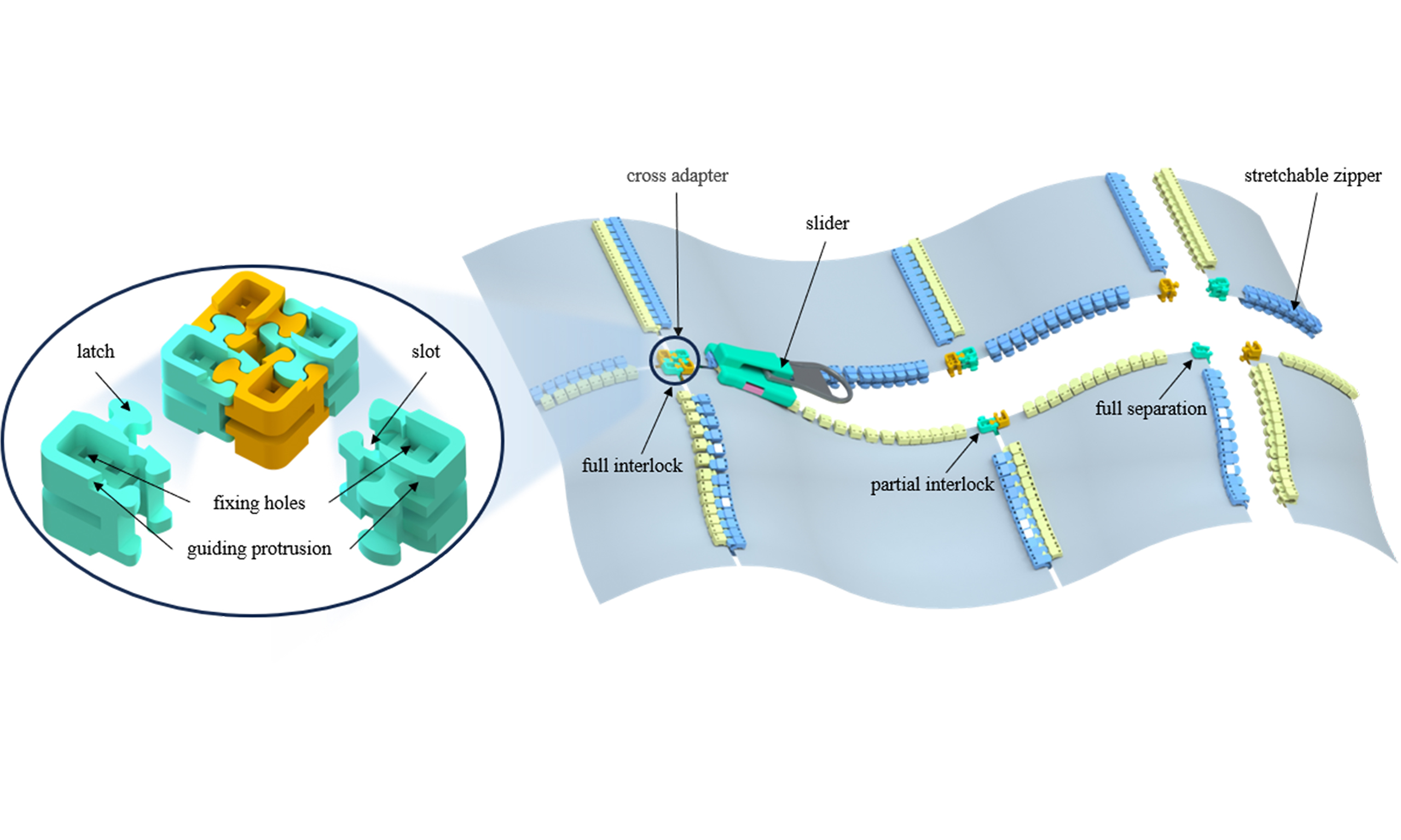
The crossed stretchable zipper, formed by orthogonally arranging stretchable zippers, exhibits distinct regimes in the overlapping region during operation - full separation, partial interlock, and full interlock - as shown in Figure 1A. To ensure normal zipper functionality, two key structural requirements are defined for this region: (1) the structure must provide interference resistance in both partial and full interlock regimes, with sufficient load-bearing capacity and low susceptibility to structural failure; (2) the structure must allow convenient, rapid, and stable transitions between regimes via the slider. Accordingly, a cross adapter based on a latch-slot mechanism and compatible with the crossed stretchable zipper is designed. It consists of four identical sub-parts [Figure 1B]. Its key functional elements include the latch and slot that intermesh to achieve interlocking, a guiding protrusion that directs and facilitates separation within the slider, and fixing holes for securing the sub-parts to the elastic band. During zipping, the sub-parts move toward each other, and interlocking occurs when one sub-part elastically deforms its slot to engage with the latch of an adjacent sub-part [Figure 1C]. Meanwhile, the design incorporates an alternating stacked suture-joint anti-separation structure to prevent the cross adapter from separating perpendicular to the interlocking surface after engagement, as shown in Figure 1D. This interlocking and anti-separation strategy provides superior interference resistance in both partial and full interlock regimes, enhancing the adaptability of the zipper to diverse application scenarios. To ensure normal zipping and unzipping of the crossed stretchable zipper, a novel slider is developed. It features symmetrically arranged movable blocks with springs on both lateral sides to assist tooth engagement[6], and it includes tracks on the top and bottom inner surfaces [Figure 1E]. During zipping, the tracks guide and constrain the cross adapter to prevent unintended rotational motion. During unzipping, the tracks interact with the guiding protrusions of the cross adapter through compression to achieve disengagement of the sub-parts. Additionally, a fixed inner sidewall is set above the movable blocks of the slider, with its lower edge higher than the teeth by Δh1 but lower than the cross adapter by Δh2, as shown in Figure 1F. This differentiated motion mechanism separates the movements of the various structural components, allowing the cross adapter to transition between regimes without interfering with the zipping or unzipping of the teeth and the top/bottom stops, as shown in Supplementary Figures 5 and 6.
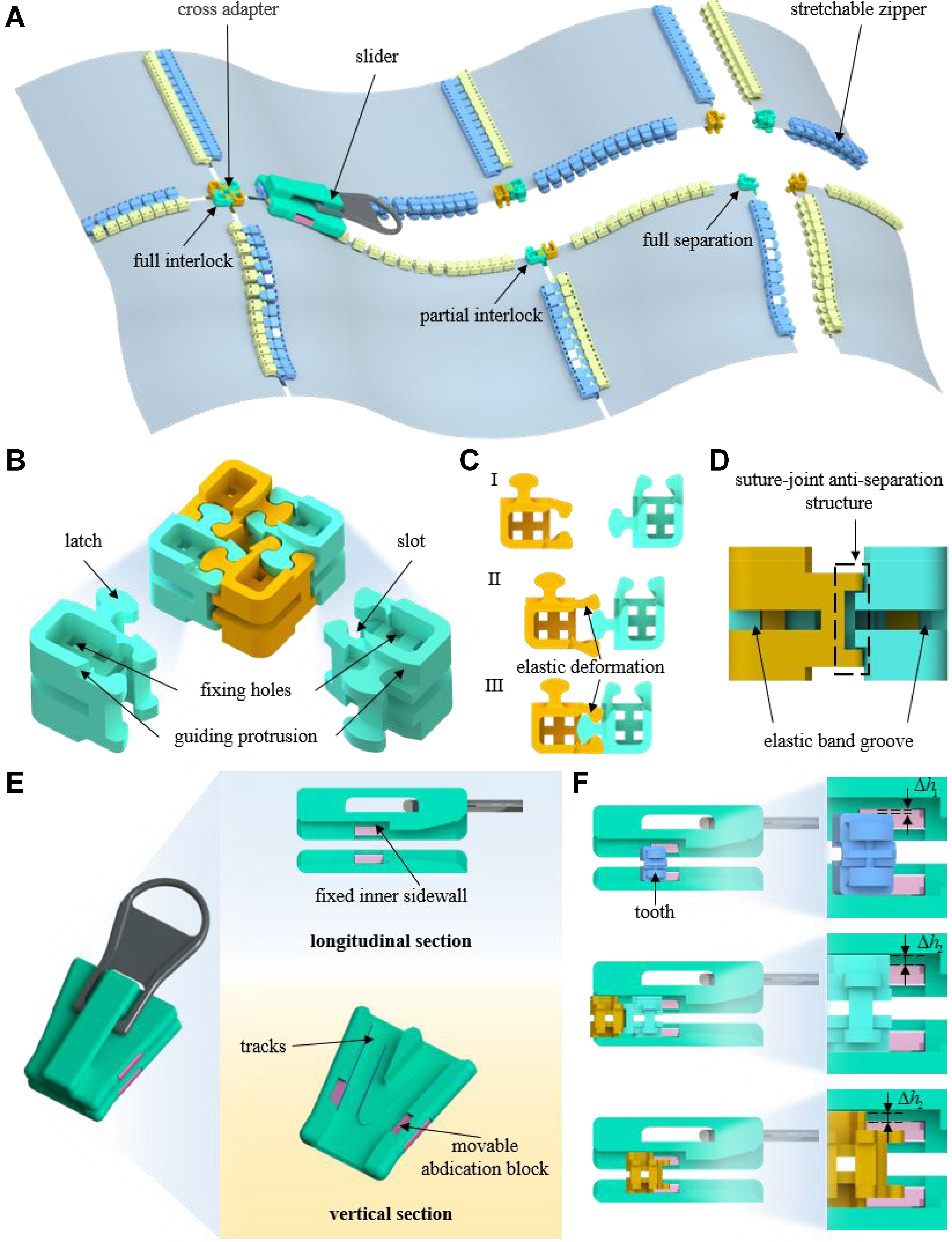
Figure 1. Structural designs of cross adapter and slider for the crossed stretchable zipper. (A) Schematic diagram of crossed stretchable zipper; (B) Specific structure of the cross adapter; (C) Interlock mechanism of the cross adapter; (D) Anti-separation mechanism of the cross adapter; (E) Specific structures of the novel slider; (F) Differentiated motion mechanism of the cross adapter.
Interlocking and mechanical properties of the cross adapter
The crossed stretchable zipper inevitably undergoes repeated zipping and unzipping. Therefore, ensuring that the cross adapter can reliably transition between regimes under varying conditions is critical. Taking the zipping of four separate elastic fabrics equipped with crossed stretchable zippers as an example, the interlocking of the sub-parts proceeds through two phases: unilateral interlocking and bilateral interlocking. During unilateral interlocking (the transition from full separation to partial interlock), the two sub-parts on the same side within the slider must be connected by sewing threads to provide sufficient traction for the subsequently interlocked sub-parts to move along the tracks. This phase consists of six regimes, as shown in Figure 2A.
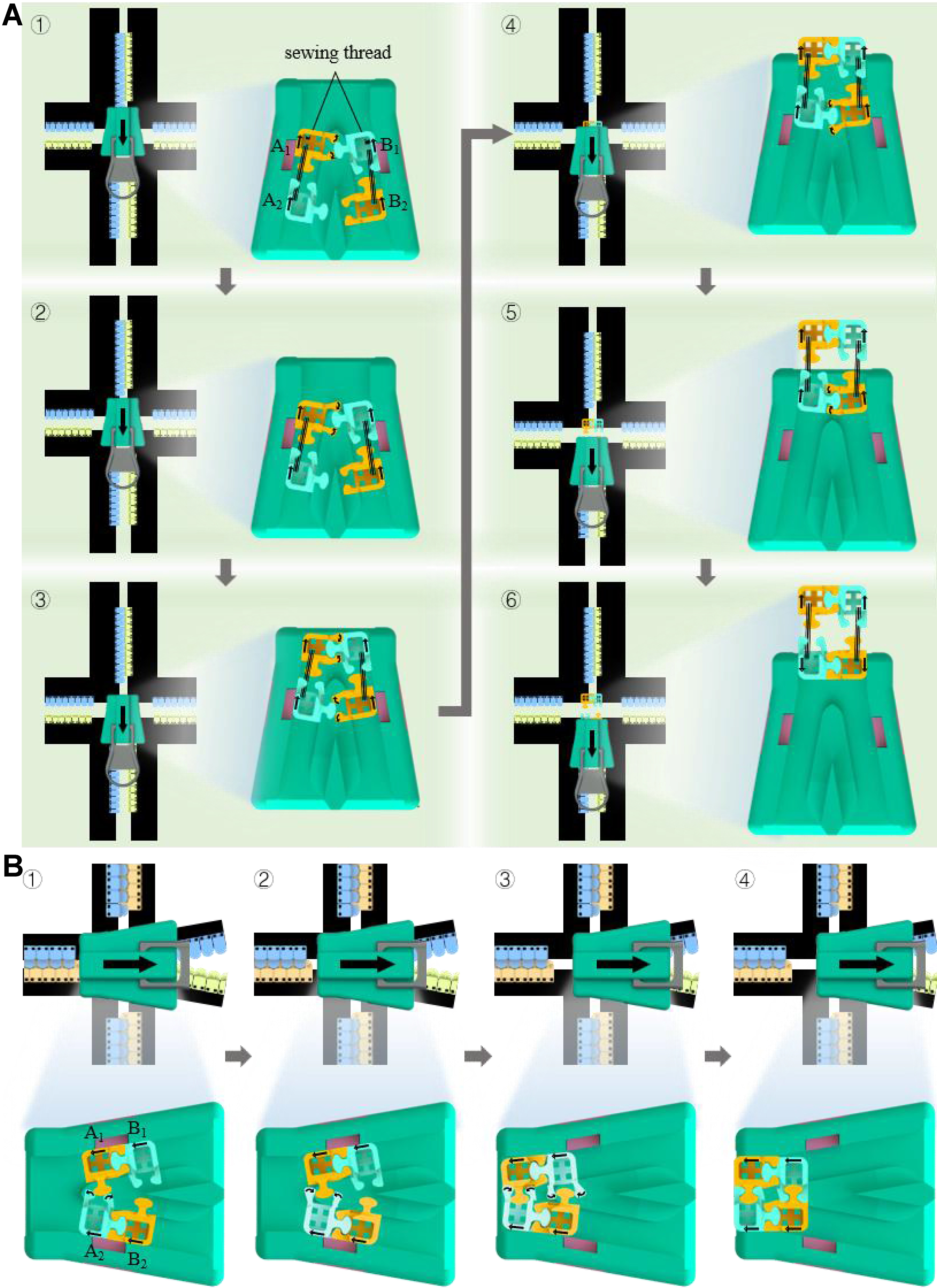
Figure 2. Phase transition processes of the cross adapter under different conditions. (A) The unilateral interlocking and (B) bilateral interlocking processes of the sub-parts of the cross adapter.
• Regime (1) As the slider moves, A1 and B1 are compressed. The two side walls of the slot in A1 undergo external rotation (i.e., rotate away from each other), while the latch of B1 is pressed against the side walls of A1.
• Regime (2) The sub-parts move along the track convergence direction. Under mutual compression between the latch and slot, the widest part of the latch in B1 contacts both side walls of the slot in A1, causing the slot walls of A1 to rotate internally (toward each other).
• Regime (3) The side walls of A1 continue to rotate internally, allowing the latch of B1 to gradually enter the slot of A1. Meanwhile, driven by the sewing-thread traction, A2 and B2 begin to compress. The slot walls of B2 rotate externally while maintaining contact with the latch of A2.
• Regime (4) A1 and B1 complete interlocking and exit the slider along the tracks. Under continued sewing-thread traction, the latch and slot of A2–B2 are further compressed. Once the widest part of the latch in A2 contacts the slot walls of B2, the slot walls of B2 begin internal rotation.
• Regime (5) Continued internal rotation of the slot in B2 allows the latch of A2 to enter the slot in B2.
• Regime (6) A2 and B2 complete interlocking and progressively exit the slider. The sewing thread is then removed.
In the above operations, the sub-parts achieve unilateral interlocking through zipping driven by the longitudinally moving slider. To realize bilateral interlocking (i.e., transition from partial interlock to full interlock), the sub-parts must be zipped by the transversely moving slider. This phase consists of four regimes, as shown in Figure 2B.
• Regime (1) Slider movement induces compression between A1 and A2. The side walls of the slot in A2 rotate externally, while the latch of A1 remains in contact with the slot walls of A2.
• Regime (2) Under mutual compression between the latch and slot, the widest part of the latch in A1 contacts the slot walls in A2, after which the slot walls in A2 begin to rotate internally.
• Regime (3) Continued internal rotation of the slot in A2 allows the latch of A1 to enter the slot of A2. Concurrently, B1 and B2 begin to compress, repeating the same interlocking steps as A1 and A2.
• Regime (4) As the slider continues moving, the sub-parts complete bilateral interlocking and exit the slider.
Both unilateral and bilateral interlocking require that the point at which sub-parts first contact inside the slider not be too close to the slider inlet; otherwise, the sub-parts may rotate around the movable blocks
The superior mechanical properties of the stretchable zipper and cross adapter are essential for ensuring the performance and practical value of the crossed stretchable zipper. While previous studies have comprehensively tested the mechanical properties of the stretchable zipper[6], it is necessary to systematically evaluate the key mechanical properties of the cross adapter under three typical scenarios: partial interlock, full interlock under symmetric stretching (both zipper tapes experience identical strain), and full interlock under asymmetric stretching (the zipper tapes experience different strains). Supplementary Text 3 details the expected practical application scenarios for these three cases. Experiments were conducted using discrete strain values, starting from 0% with increments of 5% up to 25%, which adequately capture the force trends while avoiding excessively dense data points.
Figure 3A-C illustrates the variation of the maximum zipping force across the three scenarios. Comparing Figure 3A with 3B and 3C indicates that, unlike the full interlock scenarios where two pairs of sub-parts engage simultaneously, the partial interlock scenario involves at most one pair of sub-parts. As a result, the maximum zipping force is much lower in the partial interlock scenario. Analysis of Figure 3B and C further shows that the maximum zipping force increases significantly as the strain of the tape perpendicular to the slider zipping direction rises. In contrast, changes in the strain ε2 of the tape parallel to the slider zipping direction - i.e., ε2 = 0% and 25% - have little effect on the max zipping force. This indicates that the max zipping force is considerably more sensitive to ε1 than to that ε2. Figure 3D-F displays the variation of breaking force in the three scenarios. Comparison of Figure 3D with 3E and 3F clearly shows that the breaking force in the partial interlock scenario is much lower than in the full interlock scenarios, as only half of the cross adapter bears the tensile load. Analysis of Figure 3E and F further reveals that the breaking force of the cross adapter is strongly influenced by the strain and strain difference of the two tapes along the stretching direction, while the strain ε2 of the tapes perpendicular to the stretching direction has a negligible effect. This also indicates that the sensitivity of the breaking force to ε1 is significantly higher than that to ε2. In addition, the results indicate that under asymmetric stretching of the two tapes along the stretching direction, the tape with lower strain can enhance the cross adapter’s anti-breaking performance. For example, compared with the case where both tapes have strain ε11, the scenario with one tape at 0% strain and the other at ε11 exhibits a higher breaking force. Moreover, the cross adapter typically fails through structural failure under the three scenarios, as shown in Supplementary Figure 11. Figure 3G-I shows the variation of anti-separation force across these scenarios. Consistently, the partial interlock scenario exhibits a much lower anti-separation force than the full interlock scenarios, as only one set of sub-parts resists pressure perpendicular to the interlocking surface. Under asymmetric stretching, the cross adapter experiences non-uniform load distribution. Comparison of Figure 3H and I indicates that this transforms the original simultaneous failure of the bilateral suture-joint into a sequential mechanism, where one side fails first, triggering failure on the opposite side [Supplementary Figure 12]. Consequently, the failure strength under asymmetric stretching is significantly reduced. Additionally, pressure perpendicular to the interlocking surface combined with rotation toward the higher-strain side further exacerbates failure. Furthermore, the data in Figure 3H, combined with the symmetric distribution of the suture-joint structure, indicate that longitudinal and transverse strains have equivalent effects on the anti-separation performance of the cross adapter. After 400 zipping/unzipping cycles under biaxial stretching, the cross adapter demonstrated excellent practical robustness [Supplementary Figure 13]. No observable wear, fatigue, or permanent deformation was found in any zipper components - including teeth, movable blocks, or tracks - ensuring normal differential motion and preventing jamming [Supplementary Figure 14]. Two key comfort metrics were also measured: the areal density of the crossed stretchable zipper is 0.126 g/cm2, and its bending stiffness is approximately 0.5 N·m2. Subsequently, flexible soft magnetic strips [with main functional materials including magnetic powder (SrO6Fe2O3) and chlorinated polyethylene (CPE)] are used to replace the teeth as the closing device, hereinafter referred to as the magnetically closed cross zipper. The test results of various key properties of the magnetically closed cross zipper are shown in the Supplementary Figures 15 and 16. Under the condition of 0% biaxial strain, the maximum zipping force of the magnetically closed cross zipper is significantly lower than that of the crossed stretchable zipper, while it also exhibits excellent robustness. However, its breaking force and anti-separation force are significantly lower - meaning insufficient anti-interference capability - which prevents it from well adapting to the situation where the zipper is stretched under external loads. Under the condition of a large biaxial stretching rate of the zipper
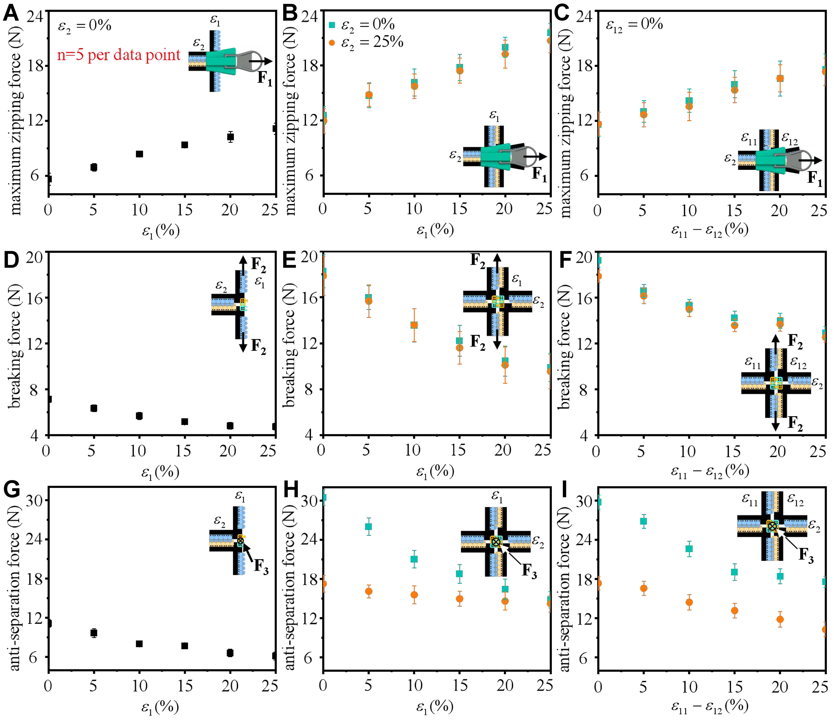
Figure 3. Mechanical properties of the cross adapter. (A-C) The maximum zipping force, (D-F) breaking force, and (G-I) anti-separation force in three typical scenarios: partial interlocking, fully interlocking under symmetric stretching, and fully interlocking under asymmetric stretching.
Application of crossed stretchable zipper in smart wearable systems
Smart wearable systems, composed of stretchable electronics and bodysuits, leverage their exceptional conformability to complex surfaces and high integration, and have rapidly developed in motion monitoring[7-12], personalized therapy[13-19], and human-machine interaction[20-22]. However, as critical components of wearable systems, electronics often require specific installation positions and angles, limiting convenient adjustment or replacement in daily use. This constraint hinders the personalized deployment of wearable systems across different scenarios. The introduction of the crossed stretchable zipper provides a practical, versatile, and modular solution for electronics integration, which is highly significant for the personalized and widespread development of smart wearable systems. For example, in hemiplegia rehabilitation following stroke, patients often experience limited upper limb mobility and reduced trunk control, severely impacting independence and quality of daily life[23,24]. To enable targeted monitoring and assisted rehabilitation for upper body impairments, the wearable system integrates upper limb motion sensors, trunk posture sensors[25], and lumbar electromyography (EMG) monitoring sensors[26], as shown in Figure 4A (right). The synergistic operation of these sensors provides accurate feedback on patients’ movement patterns, reducing compensatory motions (e.g., trunk flexion during reaching) and enhancing rehabilitation outcomes. In the event of sensor failure, patients can promptly and conveniently replace damaged electronics with pre-packaged modules. Notably, stroke incidence is higher among middle-aged and elderly populations, who often present with comorbidities; monitoring for these additional conditions is typically not included in hemiplegia rehabilitation wearable systems.
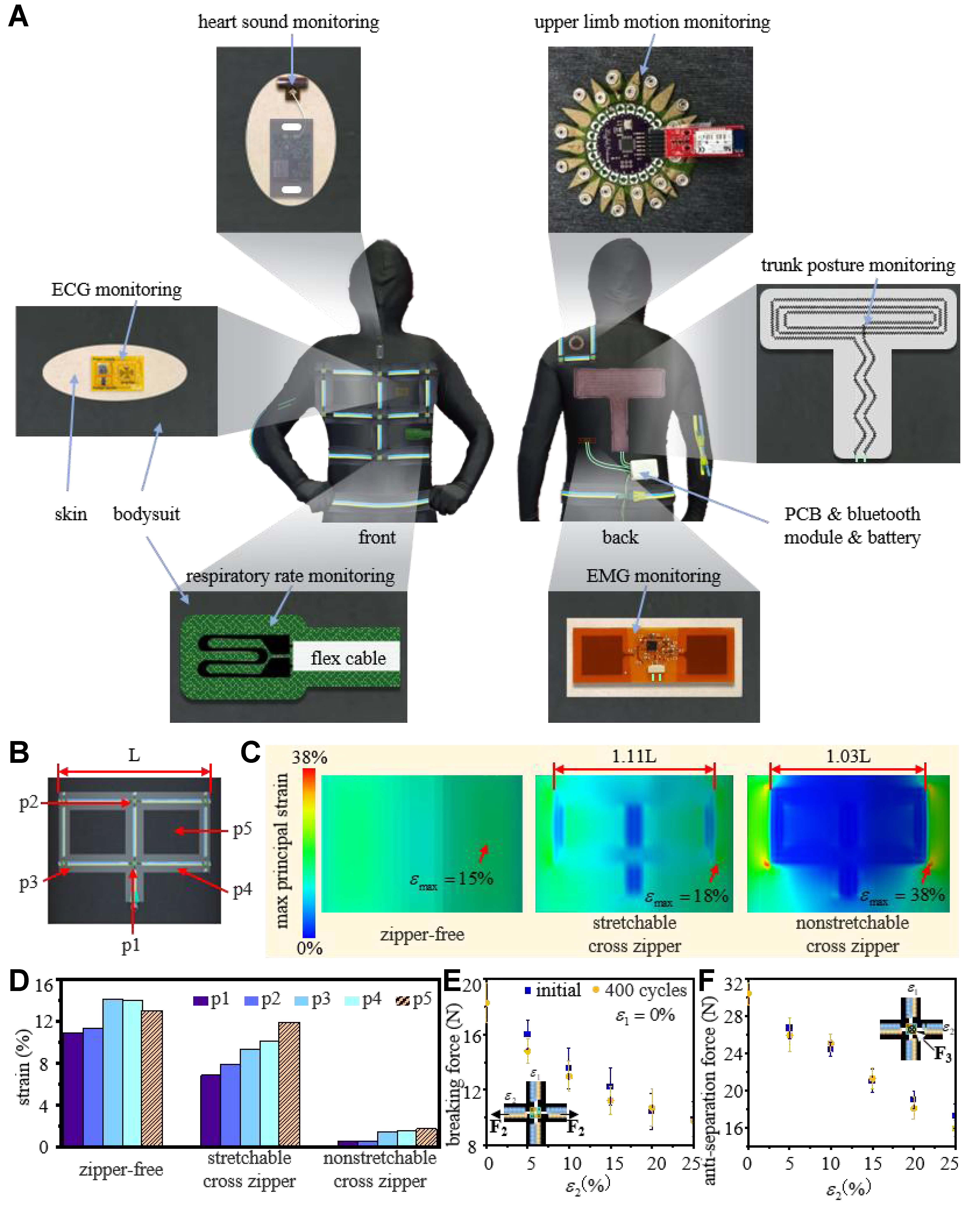
Figure 4. Application of crossed stretchable zipper in smart wearable systems. (A) Personalized implementation-based wearable system for hemiplegia rehabilitation; (B) A bodysuit equipped with cross zipper; (C) Strain distribution of bodysuits equipped with zipper-free, stretchable and crossed nonstretchable zippers during static respiration; (D) Strain diagram of the bodysuit in five key areas covered by the zipper; Changes in (E) breaking force and (F) anti-separation force under different strain conditions after the cross adapter undergoes loading-unloading cycles simulating static respiration. ECG: Electrocardiogram; EMG: electromyography; PCB: printed circuit board.
By enabling modular packaging of sensors, the crossed stretchable zipper allows patients to integrate devices on demand based on individual needs. Examples include respiratory rate sensors[27,28] for monitoring conditions such as asthma, heart sound sensors[29] for valve diseases, and ECG sensors[30,31] for heart rate and myocardial assessment, as shown in Figure 4A (left). This approach provides a robust foundation for personalized wearable system deployment. Additionally, the ability to replace damaged electronics with pre-packaged modules significantly reduces time and economic costs.
The diverse application scenarios highlight the practical value of the crossed stretchable zipper. However, with the aid of the cross adapter, conventional zippers can also be configured as crossed nonstretchable zippers, which could seemingly serve a modular role. Given the more mature technology of nonstretchable zippers, evaluating whether cross zippers require stretchability becomes essential. To address this, as shown in Figure 4B and C, and Supplementary Figure 17, the lengths of zipper-covered areas in bodysuits equipped with crossed stretchable and nonstretchable zippers of different material tapes were measured during static respiration. FEA was performed to assess the effect of these zippers on bodysuit strain during static respiration [Figure 4C and Supplementary Figure 18]. Results show that bodysuits with crossed stretchable zippers exhibit greater deformation in the zipper-covered areas, with maximum principal strain closer to that of zipper-free regions. This indicates that crossed stretchable zippers impose significantly lower strain constraints than nonstretchable zippers, enhancing conformability and comfort during breathing and movement while reducing localized sliding friction that may impair the skin barrier or trigger inflammatory responses. During static respiration [Figure 4D], considerable deformation is preserved in stretchable zipper-covered areas despite overall strain reduction. In contrast, nonstretchable zippers severely limit strain in both peripheral and internal areas, restricting the integration of deformation-based physiological monitoring devices. To further examine the impact of different bodysuit material parameters on maximum principal strain, a detailed FEA was conducted [Supplementary Figure 19]. The results show that for wearable systems equipped with crossed stretchable zippers of the same material, the bodysuit material has a negligible effect on the maximum principal strain. This aligns with expectations, as the elastic modulus of the cross adapters and zipper teeth (including nonstretchable tapes) is much higher than that of the bodysuits. During stretching, the primary factor limiting bodysuit deformation is therefore the zipper components, explaining the strain’s insensitivity to bodysuit material. This indicates that crossed stretchable zippers of the same material can be applied to conventional bodysuits of various materials without affecting deformation performance in the zipper-covered area. These findings confirm that the stretchability of cross zippers is essential for achieving excellent conformability and broad applicability of wearable systems and is a critical prerequisite for system modularization. Figure 4E and F shows changes in breaking force and anti-separation force of cross adapters under different strain conditions after 400 loading–unloading cycles simulating static respiration, demonstrating high repeatability. Signal stability tests of the flexible large-strain sensor over 800 cycles under different stretching conditions [Supplementary Figure 20] show that the use of the stretchable zipper does not adversely affect signal monitoring.
CONCLUSIONS
The crossed stretchable zipper, based on mechanical structural design, enables a 2D mesh configuration while maintaining the inherent stretching performance of the stretchable zipper, significantly enhancing flexibility and adaptability. It achieves zipping in overlapping areas through interlocking of the cross adapter’s sub-parts, suppresses structural failure via latch-slot and suture-joint mechanisms, and closes separated fabrics while retaining stretchability. The novel slider incorporates a differential motion mechanism, separating the movements of cross adapters and teeth. Application in hemiplegia rehabilitation wearables demonstrates that modularity based on the crossed stretchable zipper facilitates personalized deployment and ensures conformability, supporting the development of personalized and widely applicable wearable systems. Moreover, the crossed stretchable zipper represents a technological breakthrough for high-end equipment manufacturing, promoting the evolution of the zipper industry from simple functional components to multidimensional smart connectors.
DECLARATIONS
Acknowledgments
The authors are deeply grateful to Dr. Qinlan Li for essential contributions to the experimental workflow and data analysis, and express gratitude to Prof. Xiaoming Liu for providing the materials testing machine.
Authors’ contributions
Conceptualization: Wang, F.; Su, Y.
Methodology: Wang, F.; Su, Y.
Investigation: Wang, F.; Su, Y.
Visualization: Wang, F.; Feng, C.
Writing - original draft: Wang, F.
Writing - review and editing: Wang, F.; Feng, C.; Su, Y.; Wang, Z.
Supervision: Su, Y.; Wang, Z.
Funding acquisition: Su, Y.
Project administration: Su, Y.; Feng, C.
Availability of data and materials
All data are available in the main text or the Supplementary Materials. Additional data are available from the corresponding author upon request.
Financial support and sponsorship
This work was supported by the National Natural Science Foundation of China (Grant No. 12172359), the Key Research Program of Frontier Sciences of the Chinese Academy of Sciences (Grant No. ZDBS-LY-JSC014), and the CAS Interdisciplinary Innovation Team (Grant No. JCTD-2020-03).
Conflicts of interest
All authors declared that there are no conflicts of interest.
Ethical approval and consent to participate
This study involved only non-invasive data collection by placing the device on the skin and did not pose any health risks. According to Article 32 of the Measures for the Ethical Review of Life Science and Medical Research Involving Human Subjects (Trial), the study is exempt from formal ethical review. All participants provided informed consent prior to participation.
Consent for publication
Not applicable.
Copyright
© The Author(s) 2026.
Supplementary Materials
REFERENCES
1. Xie, C. X.; Yu, C. Q.; Wang, W.; Wang, C. L.; Yin, D. A novel zipper device versus sutures for wound closure after surgery: a systematic review and meta-analysis. Int. Wound. J. 2020, 17, 1725-37.
2. Ninan, N.; Thomas, S.; Grohens, Y. Wound healing in urology. Adv. Drug. Deliv. Rev. 2015, 82-3, 93-105.
3. Bastian, P. J.; Haferkamp, A.; Albers, P.; Müller, S. C. A new form of noninvasive wound closure with a surgical zipper. J. Urol. 2003, 169, 1785-6.
4. Jin, X.; Ding, W.; Baumert, M.; et al. Mechanical design, analysis, and dynamics simulation of a cable-driven wearable flexible exoskeleton system. Technologies 2024, 12, 238.
5. Ma, Y.; Zhou, Y.; Fang, S.; Zhang, Y.; Huang, Y.; Zhou, H. Designing with new zipper technologies: a playful modular apparel design application. Fash. Pract. 2025, 17, 345-55.
7. Kwon, K.; Lee, Y. J.; Chung, S.; et al. Full body-worn textile-integrated nanomaterials and soft electronics for real-time continuous motion recognition using cloud computing. ACS. Appl. Mater. Interfaces. 2025, 17, 7977-88.
8. Li, G.; Zhang, M.; Liu, S.; et al. Three-dimensional flexible electronics using solidified liquid metal with regulated plasticity. Nat. Electron. 2023, 6, 154-63.
9. Su, Q.; Zou, Q.; Li, Y.; et al. A stretchable and strain-unperturbed pressure sensor for motion interference-free tactile monitoring on skins. Sci. Adv. 2021, 7, eabi4563.
10. Tan, C.; Dong, Z.; Li, Y.; et al. A high performance wearable strain sensor with advanced thermal management for motion monitoring. Nat. Commun. 2020, 11, 3530.
11. Wibowo, A. F.; Han, J. W.; Kim, J. H.; et al. Highly stretchable and robust transparent conductive polymer composites for multifunctional healthcare monitoring. Sci. Technol. Adv. Mater. 2022, 23, 332-40.
12. Zou, Y.; Tan, P.; Shi, B.; et al. A bionic stretchable nanogenerator for underwater sensing and energy harvesting. Nat. Commun. 2019, 10, 2695.
13. Ahmed, A.; Jalil, M. A.; Hossain, M. M.; et al. A PEDOT:PSS and graphene-clad smart textile-based wearable electronic Joule heater with high thermal stability. J. Mater. Chem. C. 2020, 8, 16204-15.
14. Du, X.; Wankhede, S. P.; Prasad, S.; Shehri, A.; Morse, J.; Lakal, N. A review of inkjet printing technology for personalized-healthcare wearable devices. J. Mater. Chem. C. 2022, 10, 14091-115.
15. Gong, X.; Yang, J.; Zheng, Y.; et al. Polymer hydrogel-based multifunctional theranostics for managing diabetic wounds. Adv. Funct. Mater. 2024, 34, 2315564.
16. Hong, Y.; Wang, B.; Lin, W.; et al. Highly anisotropic and flexible piezoceramic kirigami for preventing joint disorders. Sci. Adv. 2021, 7, eabf0795.
17. Huang, W.; Ding, Q.; Wang, H.; et al. Design of stretchable and self-powered sensing device for portable and remote trace biomarkers detection. Nat. Commun. 2023, 14, 5221.
18. Shveda, R. A.; Rajappan, A.; Yap, T. F.; et al. A wearable textile-based pneumatic energy harvesting system for assistive robotics. Sci. Adv. 2022, 8, eabo2418.
19. Xu, H.; Zheng, W.; Zhang, Y.; et al. A fully integrated, standalone stretchable device platform with in-sensor adaptive machine learning for rehabilitation. Nat. Commun. 2023, 14, 7769.
20. Wu, R.; Ma, L.; Chen, Z.; et al. Stretchable spring-sheathed yarn sensor for 3D dynamic body reconstruction assisted by transfer learning. InfoMat 2024, 6, e12527.
21. Yin, L.; Kim, K. N.; Lv, J.; et al. A self-sustainable wearable multi-modular E-textile bioenergy microgrid system. Nat. Commun. 2021, 12, 1542.
22. Zhang, C.; Zhang, L.; Tian, Y.; An, Z.; Li, B.; Li, D. AI-enabled full-body dynamic avatar reconstruction using triboelectric smart clothing for metaverse applications. eScience 2025, 5, 100373.
23. Gular, K.; Sivasubramanian, V.; Reddy, R. S.; Tedla, J. S.; Dixit, S. The mediating effect of age, gender, and post-stroke duration on the association between trunk and upper limb recovery in subacute stroke population: a cross-sectional study with mediation analysis. Int. J. Environ. Res. Public. Health. 2022, 19, 15644.
24. Wee, S. K.; Hughes, A. M.; Warner, M. B.; Burridge, J. H. Longitudinal analysis of the recovery of trunk control and upper extremity following stroke: An individual growth curve approach. Top. Stroke. Rehabil. 2022, 29, 58-73.
25. Patiño A, Khoshnam M, Menon C. Wearable device to monitor back movements using an inductive textile sensor. Sensors 2020, 20, 905.
26. Ng, C. L.; Reaz, M. B. I.; Crespo, M. L.; et al. A flexible capacitive electromyography biomedical sensor for wearable healthcare applications. IEEE. Trans. Instrum. Meas. 2023, 72, 1-13.
27. Hsu, D.; Sung, Y.; Ni, S.; et al. Wearable pocket-sized fully noncontact biomedical eddy current sensor for simultaneous cardiac and lung monitoring. IEEE. Trans. Instrum. Meas. 2024, 73, 1-13.
28. Pegan, J. D.; Zhang, J.; Chu, M.; et al. Skin-mountable stretch sensor for wearable health monitoring. Nanoscale 2016, 8, 17295-303.
29. Demir, S. M.; Marzano, L.; Ros, P. M.; Fachechi, L.; Demarchi, D.; De Vittorio, M. Wearable multiple body signal monitoring system with single biocompatible AlN piezoelectric sensor. In 2023 IEEE International Symposium on Circuits and Systems (ISCAS), Monterey, USA. May 21-25, 2023. IEEE; 2023. p. 1-5.
30. Luo, Z.; Peng, B.; Zeng, J.; et al. Sub-thermionic, ultra-high-gain organic transistors and circuits. Nat. Commun. 2021, 12, 1928.
Cite This Article
How to Cite
Download Citation
Export Citation File:
Type of Import
Tips on Downloading Citation
Citation Manager File Format
Type of Import
Direct Import: When the Direct Import option is selected (the default state), a dialogue box will give you the option to Save or Open the downloaded citation data. Choosing Open will either launch your citation manager or give you a choice of applications with which to use the metadata. The Save option saves the file locally for later use.
Indirect Import: When the Indirect Import option is selected, the metadata is displayed and may be copied and pasted as needed.
About This Article
Copyright

Data & Comments
Data
0


Comments
Comments must be written in English. Spam, offensive content, impersonation, and private information will not be permitted. If any comment is reported and identified as inappropriate content by OAE staff, the comment will be removed without notice. If you have any queries or need any help, please contact us at [email protected].