


Stretchable zipper
 0
0 Abstract
The smart wearable system composed of stretchable electronics and bodysuits is a focus in healthcare and human-machine interaction. Despite advances in stretchable electronics, a stretchability mismatch persists between zippers and stretchable fabrics, which are key components of bodysuits, affecting the system’s function, comfort, and aesthetics. The key challenge lies in the contradiction between the requirement for closely arranged teeth in traditional zippers and the demand for stretchability in stretchable zippers. Here, we report a bio-inspired stretchable zipper, which achieves interlocking through interlaced spatulate teeth, suppresses separation perpendicular to interlocking surfaces via a suture joint, and prevents excessive inter-tooth distance by a hook-furrow structure. The novel slider provides teeth rotation space during interlocking through the reciprocation of movable blocks. The stretchable zipper can maintain interlocking and effortless zipping/unzipping over a wide range of strain and strain differences (0%-25%, respectively). In applications for hemiplegia rehabilitation wearable systems and wound closure, stretchable zippers show advantages in enhancing conformability, paving the way for smart wearable systems.
Keywords
INTRODUCTION
Smart wearable systems composed of stretchable electronics and stretchable bodysuits are capable of closely fitting the human body and providing functions such as physiological parameter monitoring for diagnosis, motion capture for human-machine interaction, and mechanical or physical actuation for rehabilitation. Millions of research papers on stretchable electronics in recent years have reported significant achievements in design, manufacturing, and applications. Stretchable fabrics, as the main component of stretchable bodysuits, have also been extensively investigated, with various materials such as spandex, modal, and neoprene. Surprisingly, however, the zipper - an indispensable component of stretchable bodysuits - is barely stretchable and has received little attention with regard to stretchability. The mechanical mismatch between stretchable fabrics and non-stretchable zippers may affect function, comfort, aesthetics, and more. According to the bucket theory of wearable systems, enabling the stretchability of zippers is of enormous significance.
Zippers, which are generally not stretchable, are composed of teeth, a slider, top and bottom stops, and two non-stretchable nylon tapes. As the slider moves along the tapes in the zipping direction, its internal structure presses the teeth laterally, inserting the tooth protrusions on one side into the grooves on the other side to interlock and bring the two tapes together. Whether the teeth are spoon-, spiral-, or arch-shaped, maintaining the compact arrangement of teeth along the length direction is the fundamental requirement for achieving zipper interlocking. Simply replacing non-stretchable nylon tapes with stretchable tapes inevitably increases the distance between teeth during stretching and consequently leads to their separation. The conflict between the need for compact tooth arrangement in traditional zippers and the demand for stretchability in stretchable zippers is the crucial challenge in structural design.
Here, we report a stretchable zipper based on bio-inspired structural designs. The teeth achieve interlocking via interlaced spatulate structures, restrain separation perpendicular to the interlocking surfaces through suture-joint structures, and prevent excessive inter-tooth distance with a hook-furrow structure. The novel slider provides sufficient rotation space for the teeth during interlocking via the periodic motion of movable blocks within the slider. The stretchable zipper maintains interlocking and enables effortless zipping/unzipping over a wide range of strain and strain differences (0%-25%, respectively), demonstrating significant advantages in adapting to stretch and enhancing conformability.
EXPERIMENTAL
FEA of stretchable zippers
The commercial software Abaqus is used for finite element analysis (FEA) to validate the effectiveness of stretchable zippers. The bodysuit and stretchable zippers are modeled as hyperelastic materials, adopting the Mooney-Rivlin hyperelastic model with the following parameters: for the bodysuit, C10 = 0.053691275, C01 = 0.013422819, D1 = 0.3; for the stretchable zippers, C10 = 0.080536913, C01 = 0.020134228, D1 = 0.2. The non-stretchable zippers with blended fabric tapes are modeled using an orthotropic model due to their limited deformation capacity and linear mechanical behavior. The Poisson’s ratios are uniformly set as ν13 = ν23 = 0.01 and the shear moduli are uniformly set as G13 = G23 = 0.05, with the remaining parameters as follows:
Fabrication process of the stretchable zipper
The fabrication processes of the teeth, top and bottom stops, slider, and movable blocks are as follows: (1) Establish 3D models of each component, slice, and add supports; (2) Use ultraviolet (UV) curable resin to perform 3D printing on each component through the stereolithography (SLA) process (SL-700); (3) Clean each printed component with isopropyl alcohol (IPA) for approximately 2-5 min until the model surface is no longer slippery; (4) Remove the supports and perform secondary curing to fully stabilize the chemical properties of the resin, achieving its maximum mechanical strength, hardness, and chemical resistance. The curing time is usually 5-15 min. The precision of each component obtained is ±0.1 mm, and the material cost of a single tooth is approximately 0.01 US dollars. Tape assembly (the remaining part of the zipper excluding the slider): An elastic tape - specifically, a common elastic band made of thermoplastic polyurethane (TPU), spandex, and latex thread - with a width of 30 mm and a thickness of 1 mm was selected. The sewing thread is a polyester thread with a specification of 40S/2. The teeth, top stops and bottom stops are fixed to the elastic tape through their fixing holes using the sewing thread. The teeth are closely arranged, and the top and bottom stops are respectively fixed at the upper and lower ends. Slider Assembly: A spring (alloy spring steel, wire diam. * outer diam. * length: 0.2 * 1.5 * 5 mm) is assembled onto the movable blocks. Then, the movable blocks are symmetrically installed on both sides of the slider. The outer surfaces of the slider and movable blocks are bonded using adhesive (Loctite 403).
Fabrication process of a wearable system platform and surgical zippers based on the stretchable
The bodysuit material consists of 87% polyester and 13% spandex, with a fabric weight of 190 g/m2. The stretchable zipper was sewn and secured to the bodysuit at the waist and joint areas using 40S/2 sewing thread.
Medical-grade hypoallergenic acrylate glue is evenly applied to the elastic tape of the stretchable zipper, which is then affixed to the skin. Initial curing was completed within approximately 10 s at body temperature, with maximum adhesive strength achieved after 4 days. During application, the stretchable zipper should extend at least 1 cm beyond both ends of the wound, and the teeth should be positioned about 0.5 cm from each side of the wound.
Experiment to measure anti-separation force of stretchable zippers
The stretchable zippers, with an unstretched length of 75 mm, are fixed at both ends using clamps of different sizes to achieve specified strains (0%, 5%, 10%, 15%, 20%, 25%) under equal strain conditions on both tapes. An indenter with a hemispherical tip (radius 1.5 mm) is used to press the surface of tooth 1 at a constant speed of 60 mm/min in a direction perpendicular to the zipper’s interlocking surface until structural failure occurs (indenter penetration of the interlocked surface). Each experiment is repeated five times under the same strain.
Experiment to measure maximum zipping force under same and different strains of two tapes
Two tapes with the same strains: The stretchable zippers, with an unstretched length of 200 mm, are fixed at both ends using tensile tester clamps. Varying strains (0%, 5%, 10%, 15%, 20%, 25%) are applied by adjusting the distance between the clamps. A small section of the zipper is initially closed. The tensile tester pulled at a constant speed of 1,250 ± 50 mm/min, and the maximum value displayed by the instrument is recorded as the maximum zipping force.
Two tapes with the different strains: A double-fixing method is used to precisely control the initial strain on each tape of the zippers (200 mm unstretched length). First, both ends of the two tapes are fixed, maintaining a constant initial strain of 0% for both tooth-1 and tooth-2 tapes. Then, curved clamps of different sizes are used to apply an additional adjustable strain specifically to the tooth-2 tape, achieving strain differences of 0%, 5%, 10%, 15%, 20%, and 25%. A small section of the zipper is closed, and the tensile tester pulls at a constant speed of 1,250 ± 50 mm/min. The maximum value displayed is recorded as the maximum zipping force. Each condition is tested five times.
Experiment to measure breaking force per unit length under same and different strains of two tapes
Two tapes with the same strains: Stretchable zippers with an unstretched length of 75 mm are fixed at both ends using tensile tester clamps. Different strains (0%, 5%, 10%, 15%, 20%, 25%) are applied by adjusting the distance between the clamps. The clamps grip the elastic tape along the width direction, with the clamp jaws positioned immediately adjacent to the teeth. The tester pulled at a constant speed of 300 ± 10 mm/min until either the teeth detach or the tape ruptures. The force value at failure, divided by the zipper length, gives the breaking force per unit length.
Two tapes with the different strains: The double-fixing method is used on zippers (75 mm unstretched length) with curved clamps to achieve strain differences of 0%, 5%, 10%, 15%, 20%, and 25%. The tooth-1 tape is maintained at 0% strain, while the tooth-2 tape strain is adjusted. Clamps with curved jaws grip the tape width, ensuring the jaws are positioned immediately adjacent to the teeth. Testing proceeded at 300 ± 10 mm/min until failure. The breaking force per unit length is calculated. Each condition is tested five times.
Experiment to measure slider lock holding force
A partially zipped stretchable zipper (100 mm unstretched length) is used. The separated ends of the tapes are clamped into the upper and lower fixtures (distance ~75 mm) and locked. The tester pulled at 300 ± 10 mm/min until the slider disengaged or the zipper failed. The displayed value is the slider locking force. Each condition is tested five times.
Experiment to measure remaining strength of zipper components
Single Tooth Gripping Strength: A 50 mm zipper is used, with teeth removed behind the first tooth on one tape to allow clamping (ensuring only one tooth is within the grip). The other end is fixed. Pull at 300 ± 10 mm/min until the test tooth detached.
Pin/Box (Bottom Stop 1 & 2) Transverse Gripping Strength, Top Stop Gripping Strength: Similar procedure to single tooth test, but the gripped component is the pin, box, or top stop.
Open-End Strength: A 50 mm zipper with a bottom stop is used. Clamps gripped the tape immediately adjacent to the bottom stop, aligned with the edges of the pin/box. Pull at 300 ± 10 mm/min until tape separation or failure.
Top Stop Strength: A 50 mm zipper with a top stop is used. The end away from the top stop is fixed. The slider pull-tab is gripped. Pull at 300 ± 10 mm/min until tape failure or slider disengagement.
Bottom Stop Strength: A 50 mm zipper with a bottom stop is used. The slider is positioned next to the bottom stop. The separated tape ends are gripped by upper and lower clamps (equal tape length, distance ~75 mm). Pull at 300 ± 10 mm/min until zipper failure.
RESULTS AND DISCUSSION
Bio-inspired structure designs for the stretchable zipper
The key challenges in achieving zipper stretchability are adapting the interlocking mechanism (y-axis) to stretching (x-axis), maintaining interlocking (y-axis) within the designed stretching limit (x-axis), and resisting separation perpendicular to the interlocking surface (z-axis). Attempts are made to seek inspiration from nature for the structural design of stretchable zipper. (1) Interlaced-spatulate teeth. Diatoms of the genus Aulacoseira are capable of interconnecting with the conspecific diatoms through the spatulate linking spines on valve faces [Figure 1A][1-4]. Meanwhile, the porous structure of the diatom frustule enables it to exhibit stretchability[5,6], similar to that of certain engineering foam materials. Inspired by this interlocking mechanism, interlaced-spatulate teeth are designed. The neck proportion of the improved teeth is greatly reduced, providing a larger contact area for interlocking between teeth and enhancing the stretch limit of the zipper; (2) Hook-furrow stretching limiter. Honeybees couple the hamuli (hooks) arranged on hindwings with the posterior recurved margin of the forewings to form a hook-furrow structure
Figure 1. A bio-inspired stretchable zipper. (A) Aulacoseira genus diatoms interlock through spatulate linking spines[4]. Reprinted with permission. Copyright 2024, Elsevier; (B) The honeybee connects the forewings and hindwings through the hook-furrow structure to ensure the synchronization of their flapping during flight[10]. Reprinted with permission. Copyright 2019, Elsevier; (C) Suture-joint significantly enhances the exoskeleton’s crush resistance by locking the beetle’s hardened forewings together[15]. Reprinted with permission. Copyright 2024, Springer Nature. (D) A bio-inspired stretchable zipper.
Mechanical analysis for the stretchable zipper
It is crucial to ensure the proper functioning of the zipping and unzipping processes when the two tapes are under different strains. The bio-inspired zipper illustrated in Figure 2A and B indicates that the teeth and their interlocked structures are capable of adapting to tape stretching, while the remaining work is to design a novel slider that can be compatible with tape stretching. As shown at the top of Figure 2C, tracks are arranged on the top and bottom surfaces of the slider, and movable blocks equipped with springs are symmetrically disposed on both lateral sides. The movable blocks are designed to exceed the inner sidewall of the slider to ensure that the teeth remain interlocked under minor disturbances as shown in the bottom of Figure 2C. During the zipping process, the teeth sequentially undergo three regimes: pre-interlock, interlocking, and interlocked, as shown in the left of Figure 2D. The first pair of teeth propels the movable blocks during zipping until their front surfaces become coplanar with the inner sidewalls of the slider, facilitating subsequent teeth interlocking. The initial contact conditions between the teeth vary depending on different tape strains, leading to discrepancies in interlocking processes. The analysis of the sources of discrepancies revealed that, as shown in Supplementary Texts 1-4 and Supplementary Figures 2 and 3, the interlocking modes can be classified into two distinct categories demarcated by the strain values ε1 = ε2 = 15.0%: bilateral equivalent interlocking (symmetrical interlocking processes on both sides’ teeth) and bilateral non-equivalent interlocking (asymmetrical interlocking processes on both sides’ teeth). Taking a typical bilateral non-equivalent interlocking characterized by 15.0% = ε1 < ε2 as an example, the interlocking processes within the slider can be divided into seven sequential steps, as outlined below [Figure 2E].
Figure 2. Key structure designs of stretchable zipper and bilateral non-equivalent interlocking process. (A) Stretchable zipper under different conditions and (B) the specific structure of its teeth; (C) The specific structures of the novel slider; (D) The novel slider zipping two tapes with different strains; (E) A typical bilateral non-equivalent interlocking process; Under the condition of 15.0% = ε1 ≤ ε2, (F) the initial contact behavior of teeth within the slider during the zipping process.
Step I: With the translation of the slider, A2 performs internal rotation (rotate toward the opposing teeth); B3 and A3 undergo external rotation (rotate away from the opposing teeth). Movable blocks M1 and M2 provide additional space for the rotation of the teeth. The boundary between these blocks and the inner sidewalls of the slider serves as the rotation axis for the teeth. During the step, M1 and M2 are gradually compressed by A3 and B3, respectively.
Step II: A2 continues internal rotation while A3 and B3 sustain external rotation. This motion continues until the compression between the arc surfaces of A2 and B3 is fully removed and A2 completes interlocking with B2. In this step, M1 and M2 are further compressed by A3 and B3, respectively.
Step III: B3 undergoes internal rotation propelled by M2 and initiates interlocking with A2. A3 continues external rotation under the compression of B3 and further compresses M1. Simultaneously, M2 recovers from compression until its front surface is coplanar with the inner sidewall of the slider.
Step IV: B3 continues internal rotation while A3 sustains external rotation. Motion continues until A3 comes into contact with B4.
Step V: B3 performs internal rotation; A3 and B4 undergo external rotation. M1 and M2 are compressed by A3 and B4.
Step VI: B3 maintains internal rotation, while A3 and B4 undergo external rotation. Concurrently, M1 and M2 are compressed by A3 and B4, respectively. Motion persists until B3 completes interlocking, and the compression between the arc surfaces of A3 and B3 is fully eliminated.
Step VII: A3 undergoes internal rotation propelled by M1 while B4 continues external rotation under the compression of A3. This kinematic progression continues until B4 comes into contact with A4. During the step, M1 recovers from compression until its front surface is coplanar with the inner sidewall of the slider. Subsequently, A4 and B4 repeat the above steps to initiate interlocking. Furthermore, when the strain values satisfy 15.0% < ε1 < ε2 ≤ 25.0%, the teeth exhibit a bilateral equivalent interlocking mode, as demonstrated in Supplementary Figure 4. Conversely, under conditions where ε1 < 15.0% < ε2 ≤ 25.0%, the teeth manifest a degenerate form of the bilateral non-equivalent interlocking mode, as shown in Supplementary Figure 5. The unzipping processes is the reverse of the zipping processes. Therefore, there is no need to go into details here.
A critical factor in achieving proper interlocking is ensuring that the teeth can rotate on the movable blocks under the compression from adjacent teeth. Taking the external rotation of A3 as an example, the internal rotation moment generated by various forces acting on A3 is inherently limited. To ensure that A3 can initiate external rotation, the force exerted by B3 on the rotation axis (O1) of A3 must generate an external rotation moment [Figure 2F] that satisfies the inequality:
where N is the normal force exerted by B3 on A3, L = 5.6 mm represents the distance between the center of the arc surface of the tooth and its posterior surface, α = arccos(1/2 - Δε) is the angle between the direction of the normal force and the symmetry plane of the slider, θ = π/18 is the angle between the track and the symmetry plane of the slider, d = 1.3 mm represents the distance from the centroid of the posterior surface of the tooth to the rotation axis O1, μ = 0.5 is the friction coefficient between teeth, and R = 2.4 mm is the radius of the arc of the tooth. Upon simplification and parameter substitution, the inequality is derived as:
The permissible range for Δε is [0.0%, 25.0%]. Practically, since the lower limit of strain for stretchable zippers must inherently be 0%, the strain ranges for both side tapes fall within [0.0%, 25.0%]. Under this condition, the external rotation moment exerted by B3 on A3 intensifies with increasing zipping force until A3 is compelled to rotate. Once rotation commences, the contact point of the force exerted by B3 on A3 moves along the arc surfaces of A3 toward arc endpoint, resulting in a moment that retains the property of inducing external rotation in A3. Analysis of B3 leads to a similar conclusion: as zipping force increases, the external rotation moment exerted by A2 on B3 intensifies until it exceeds the internal rotation moment generated by various forces acting on B3, ultimately causing B3 to continue to rotate. To ensure that the stretchable zipper does not require excessive zipping force, the slider structure is optimized, as shown in Supplementary Text 5 and Supplementary Figure 6.
Anti-separation perpendicular to the interlocking surface is a crucial factor in ensuring the normal functionality of zippers. As illustrated in the right of Figure 1D, the anti-separation mechanism of interlocked teeth is to disperse the force exerted on the locality of teeth to the adjacent area through a suture-joint structure. Based on differences in force dispersion, two structures are identified: the tooth-to-tooth anti-separation structure (TTASS, Figure 2B) and the tooth-to-elastic band-and-tooth anti-separation structure (TETASS, Supplementary Figure 7). TTASS disperses forces to adjacent teeth, while TETASS distributes forces to both adjacent teeth and the opposing elastic band. Comparative analysis under equal tape strain [Supplementary Figure 8] shows that TTASS provides superior anti-separation performance within limited space. Therefore, TTASS is adopted in the stretchable zipper.
To demonstrate the zipper’s performance and practical value, various properties of the stretchable zipper were systematically tested, with particular focus on the effects of strain differences. Figure 3A illustrates the variations in maximum zipping force under conditions of two tapes with the same strains, with experimental results demonstrating that the force meets general application standards. Furthermore, precise control of zipper strain difference is achieved through a dual fixation methodology: the tape on the tooth 1 side is maintained at a constant initial strain of 0% by fixing both ends of the two tapes, while curved fixtures of varying sizes are additionally employed to implement adjustable strain on the tooth 2 side tape. Figure 3B demonstrates the variation in maximum zipping force of two tapes with strain difference. A comparative analysis between Figure 3A and B reveals that under the condition of constant strain on the higher-strain side tape, the presence or absence of strain difference exerts negligible influence on the maximum zipping force of the stretchable zipper, which is manifested as having almost no impact on the zipping experience of the stretchable zipper. The capacity of a highly practical stretchable zipper to resist damage from external forces in the width direction cannot be ignored. The experiments are conducted under identical strain and strain differences control strategies. Comparative analysis under equal and unequal tape strains [Figure 3C and D] shows that, when the higher-strain tape is held at constant strain, the presence of a strain difference does not reduce the zipper’s breaking force per unit length. This can be explained by the increased contact area within the interlocking region under these conditions, which enhances the strength of the interlock structure. Moreover, compared to standard industrial specifications (equivalent breaking force per unit length ≈ 4 N), this stretchable zipper demonstrates superior mechanical performance. Further analysis of failure modes indicates that zipper failure is consistently caused by material damage under any strain and strain difference conditions. This shows that the stretchable zipper structure is reliable, and the employment of higher-strength materials can enhance the breaking force per unit length. Practically, stretchable zippers are frequently subjected to complex external forces. Having slider lock holding force is an indispensable element to ensure a satisfactory application experience. The stepped design between the movable blocks and the inner sidewalls guarantees that the teeth are not separated by slight disturbances exerted on the unzipped part, as shown in Figure 3E. Furthermore, to demonstrate that each component of the stretchable zipper possesses sufficient strength, destructive tests are carried out respectively on individual teeth, top stop, and bottom stops 1 and 2, as shown in Supplementary Figures 9 and 10. By comparing the results with the breaking force of the zipper [Figure 3F], it can be found that both the individual and interlocked components exhibit excellent mechanical properties, ensuring the normal use of the zipper in complex external forces.
Figure 3. Mechanical properties of stretchable zipper. Maximum zipping force (A) under conditions of two tapes with the same strain or (B) different strains; Breaking force per unit length (C) under conditions of two tapes with the same strain or (D) different strains; (E) Slider lock holding force; (F) Strength of each component of the zipper.
Applications in smart wearable systems and medical devices
Smart wearable systems composed of stretchable electronics and stretchable bodysuits enable real-time, non-invasive monitoring and analysis of human physiological signals or environmental parameters, exhibiting such advantages as high adaptability and integration. As a commonly used platform for constructing wearable systems, stretchable bodysuits are typically secured with zippers on the chest or back, or have oversized necklines to enable convenient donning/doffing. However, this restricts the placement range of various monitoring and therapeutic components and the accuracy of signal collection. Examples include posture monitoring sensors[17] placed on the chest and back, and motion control sensors[18-20] arranged at the neck. The introduction of stretchable zippers enables their placement in areas beyond the chest and back, such as the waist, which undergoes significant deformation but has lower sensor placement requirements. For example, in hemiplegia rehabilitation following stroke - a condition caused by cerebrovascular damage that impairs motor control on one side of the body - this flexibility can improve patient comfort and the effectiveness of wearable systems, ultimately enhancing independence and quality of daily life. Therefore, whole body rehabilitation after the onset is crucial. The symptoms of hemiplegia are complex and diverse, primarily manifested as limited mobility of the upper and lower limbs, decreased trunk control ability, foot varus, and more. In the rehabilitation process, it is essential to monitor the movement trajectory of the affected limb, trunk mobility, joint flexion capacity, and plantar pressure distribution. Additionally, compensatory movements, such as trunk flexion during reaching and ambulation, may negatively affect motor improvement during rehabilitation. To enable targeted monitoring and assisted rehabilitation of the affected areas, a smart wearable system equipped with stretchable zippers is proposed, integrating sensors for upper limb motion monitoring[21], trunk posture monitoring[17,18], gait monitoring[21-23], joint angle monitoring[18,24-27], and plantar pressure balance monitoring[28,29], as illustrated in the right of Figure 4A. The wearable system, through the synergistic collaboration of its integrated sensors, enables accurate feedback on patients’ movement patterns, assists the reduction of compensatory motions, and improves the rehabilitation effect. Furthermore, hemiplegia may induce edema at the joints, resulting in restricted joint mobility and persistent pain. The arrangement of stretchable zippers at affected areas, such as knees and elbows, enables convenient pressure adjustment to alleviate edema without imposing excessive constriction on joints, and avoids the need to doff clothing or detach sensors, as shown on the left side of Figure 4A.
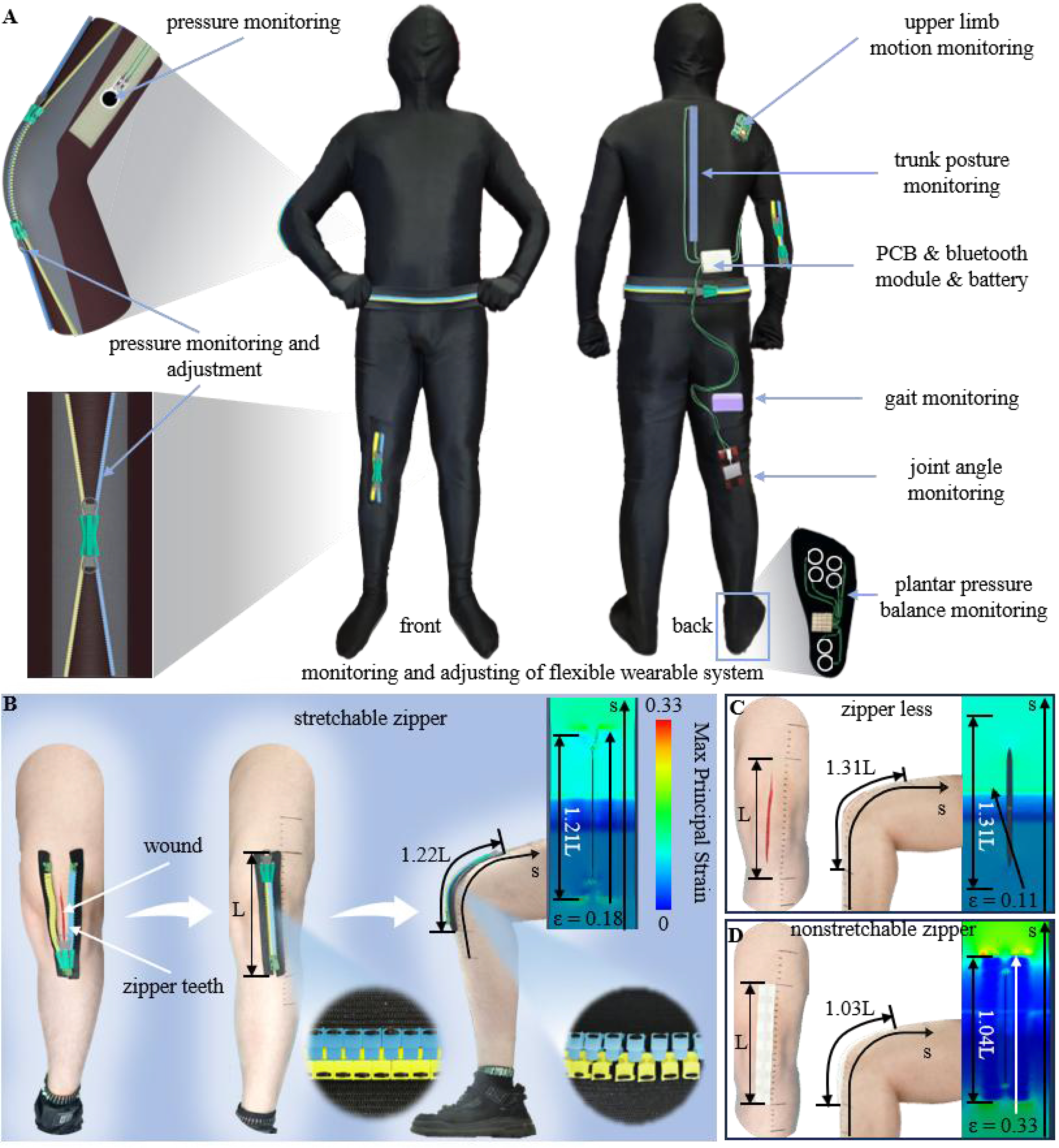
Figure 4. Applications in smart wearable systems and medical devices. (A) The hemiplegia rehabilitation wearable system; (B-D) Application in wound closure. (B) Stretchable zipper enables effective wound closure and provides adequate comfort during joint flexion; (C) An untreated wound exhibits low peripheral strain but poor healing due to exposure to air; (D) Non-stretchable zipper may induce a significant sensation of restriction during joint flexion.
Surgical zippers achieve uniform wound closure through epidermal traction, promoting healing[30,31] and reducing scarring[30,32], while concurrently demonstrating advantages including non-invasive characteristics[30], reduced infection[31], and lower cost[30,32]. However, the poor stretchability of the conventional surgical zippers results in an obvious sense of restriction when applied at joints (e.g., elbow and knee), potentially compromising the motion range of the joint. Using a stretchable zipper as a substitute can address the limitations of non-stretchable surgical zippers and expand their application scope. Taking a knee joint wound as an example, stretchable and non-stretchable zippers are used to treat the wounds, and both physical measurements and FEA are employed to compare the two strategies. Untreated wounds of the same length are set at the same position as a control group. FEA results indicated that during 90° knee flexion, the maximum principal strain around the wound treated with the stretchable zipper is close to that of the control group, but significantly lower than that of the non-stretchable zipper group [Figure 4B-D]. This difference is reflected in the fact that the stretchable zipper causes less pain during joint motion. Under identical conditions, comparing the overall strain of zippers during 90° knee flexion shows that the stretchable zipper exhibits a strain εstretchable = 0.2. This value is closer to the strain of control group εcontrol = 0.3 and is significantly higher than the overall strain of the non-stretchable surgical zipper εnonstretchable = 0.03. This is in satisfactory correspondence with the results from the FEA and indicates that the wound treated with the stretchable zipper imposes less constraint on knee flexion. Attention should also be paid to: the wound closure property of zippers, the zipping and unzipping force, and the property to avoid structure failure during joint flexion when using the stretchable zipper for wound closure. These correspond to the breaking force per unit length, maximum zipping force, and anti-separation force of the stretchable zipper, respectively. These mechanical properties have been systematically tested, as shown in Figure 3, and have been thoroughly compared with the corresponding properties of traditional zippers under the standard QB/T 2172-2014. A comparative analysis can be conducted here to further demonstrate the superiority of the stretchable zipper’s mechanical properties for wound closure. In addition, compared with non-stretchable surgical zippers, which have limited adaptability to curved wounds with large turning angles (≥ 20°), the stretchable zipper shows relatively satisfactory adaptability, as shown in Supplementary Figure 11.
CONCLUSIONS
The stretchable zipper, based on bio-inspired structural designs, effectively alleviates the stretchability mismatch between zippers and stretchable fabrics, which are key components of bodysuits. The teeth achieve interlocking via interlaced spatulate structures, restrain separation perpendicular to interlocking surfaces through suture-joint structures, and prevent excessive inter-tooth distance via a hook-furrow structure. The novel slider provides teeth rotation space during interlocking through the reciprocation of movable blocks. These designs address the contradiction between the need for closely arranged teeth in traditional zippers and the demand for stretchability, enabling the zipper to maintain interlocking and effortless zipping/unzipping over a wide range of strains and strain differences. Applications in hemiplegia rehabilitation wearable systems and wound closure demonstrate significant advantages in adapting to stretch and enhancing conformability. As the final critical component in smart wearable systems, the stretchable zipper minimizes the impact of stretchability mismatch on system function while maintaining comfort and aesthetics, paving the way for advanced smart wearable designs. The current design has limitations, such as a maximum achievable strain of 25%, which may be insufficient for applications requiring larger strains. Future work will focus on optimizing the slider and tooth structures to enhance stretchability, reduce size, and improve adaptability and zipping performance.
DECLARATIONS
Acknowledgments
The authors thank Prof. Xiaoming Liu for providing the materials testing machine.
Authors’ contributions
Conceptualization: Wang, F.; Su, Y.; Wang, Z.
Methodology: Wang, F.; Su, Y.
Investigation: Wang, F.; Su, Y.
Visualization: Wang, F.
Writing - original draft: Wang, F.
Writing - review and editing: Wang, F.; Li, Q.; Su, Y.; Wang, Z.
Supervision: Su, Y.; Wang, Z.
Funding acquisition: Su, Y.
Project administration: Su, Y.; Wang, Z.
Availability of data and materials
All data are available in the main text or the Supplementary Materials. Additional data are available from the corresponding author upon request.
Financial support and sponsorship
This work was supported by the Key Research Program of Frontier Sciences of the Chinese Academy of Sciences (Grant Number: ZDBS-LY-JSC014); CAS Interdisciplinary Innovation Team (Grant Number: JCTD-2020-03); National Natural Science Foundation of China (Grant Number: 12172359).
Conflicts of interest
All authors declared that there are no conflicts of interest.
Ethical approval and consent to participate
This study only conducted non-invasive data collection through simply placing the device on the skin, and does not involve invasive procedures or human health risks. According to Article 32 of the “Measures for the Ethical Review of Life Science and Medical Research Involving Human Subjects (Trial)”, this study meets the conditions for exemption from review. All participants participated in the experiment with informed consent.
Consent for publication
Not applicable.
Copyright
© The Author(s) 2025.
Supplementary Materials
REFERENCES
1. Bicudo, D. C.; Tremarin, P. I.; Almeida, P. D.; et al. Ecology and distribution of Aulacoseira species (Bacillariophyta) in tropical reservoirs from Brazil. Diatom. Res. 2016, 31, 199-215.
2. Casa, V.; López Bedogni, G.; Van de Vijver, B. A new Aulacoseira species (Bacillariophyta) from Tierra del Fuego (Argentina) and comparison with the type material of Melosira laevis var. fuegiana Frenguelli. Diatom. Res. 2017, 32, 409-16.
3. Tremarin, P. I.; Loverde-Oliveira, S. M.; Ludwig, T. V.; Torgan, L. C. Ultrastructure and distribution of Aulacoseira gessneri. Diatom. Res. 2011, 26, 189-97.
4. Ageli, M. K.; Hamilton, P. B.; Bramburger, A. J.; et al. Morphological variation in extinct Aulacoseira (Bacillariophyta) species from Lake Towuti, with a description of novel species. J. Great. Lakes. Res. 2024, 50, 102230.
5. Hamm, C. E.; Merkel, R.; Springer, O.; et al. Architecture and material properties of diatom shells provide effective mechanical protection. Nature 2003, 421, 841-3.
6. Soleimani, M.; van Breemen, L. C. A.; Maddala, S. P.; et al.
7. Toofani, A.; Eraghi, S. H.; Khorsandi, M.; et al. Biomechanical strategies underlying the durability of a wing-to-wing coupling mechanism. Acta. Biomater. 2020, 110, 188-95.
8. Ma, Y.; Ning, J. G.; Ren, H. L.; Zhang, P. F.; Zhao, H. Y. The function of resilin in honeybee wings. J. Exp. Biol. 2015, 218, 2136-42.
9. Eraghi, S. H.; Toofani, A.; Khaheshi, A.; et al. Wing coupling in bees and wasps: from the underlying science to bioinspired engineering. Adv. Sci. 2021, 8, e2004383.
10. Ma, Y.; Ren, H.; Rajabi, H.; Zhao, H.; Ning, J.; Gorb, S. Structure, properties and functions of the forewing-hindwing coupling of honeybees. J. Insect. Physiol. 2019, 118, 103936.
11. Wickramasinghe, S.; Peng, C.; Ladani, R.; Tran, P. Analysing fracture properties of bio-inspired 3D printed suture structures. Thin. Walled. Struct. 2022, 176, 109317.
12. Li, J.; Sui, C.; Sang, Y.; et al. A flexible, reusable and adjustable high-performance energy absorption system inspired by interlocking suture structures. Int. J. Solids. Struct. 2024, 296, 112839.
13. Wickramasinghe, S.; Al-Ketan, O.; Peng, C.; Tee, Y. L.; Kajtaz, M.; Tran, P. Influence of design parameters on the flexural properties of a bio-inspired suture structure. Virtual. Phys. Prototyp. 2023, 18, e2204845.
14. Chen, P. Y. Diabolical ironclad beetles inspire tougher joints for engineering applications. Nature 2020, 586, 502-4.
15. Rivera, J.; Hosseini, M. S.; Restrepo, D.; et al. Toughening mechanisms of the elytra of the diabolical ironclad beetle. Nature 2020, 586, 543-8.
16. Suh, I. W.; Kim, J.; Chanchamnan, S.; et al. Diabolical ironclad beetle elytra-inspired flexible WE43 magnesium endovascular stent structures and their biomechanical potential. J. Magnes. Alloys. 2025, 13, 709-18.
17. Lin, R.; Kim, H. J.; Achavananthadith, S.; et al. Wireless battery-free body sensor networks using near-field-enabled clothing. Nat. Commun. 2020, 11, 444.
18. Li, C.; Liu, D.; Xu, C.; et al. Sensing of joint and spinal bending or stretching via a retractable and wearable badge reel. Nat. Commun. 2021, 12, 2950.
19. Hong, Y.; Wang, B.; Lin, W.; et al. Highly anisotropic and flexible piezoceramic kirigami for preventing joint disorders. Sci. Adv. 2021, 7, eabf0795.
20. Wang, X.; Xiong, L.; Dong, W.; Guo, Z.; Huang, Y.; Yao, D. Flexible strain sensor based on conductive hydrogel/KC@PDMS for neck motion control wheelchair using EMD-LSTM algorithm. IEEE. Sensors. J. 2024, 24, 4079-90.
21. Liu, S.; Zhang, J.; Zhang, Y.; Zhu, R. A wearable motion capture device able to detect dynamic motion of human limbs. Nat. Commun. 2020, 11, 5615.
22. Kim, K. K.; Ha, I.; Kim, M.; et al. A deep-learned skin sensor decoding the epicentral human motions. Nat. Commun. 2020, 11, 2149.
23. Olivares, A.; Olivares, G.; Mula, F.; Górriz, J.; Ramírez, J. Wagyromag: wireless sensor network for monitoring and processing human body movement in healthcare applications. J. Syst. Archit. 2011, 57, 905-15.
24. Hannigan, B. C.; Cuthbert, T. J.; Ahmadizadeh, C.; Menon, C. Distributed sensing along fibers for smart clothing. Sci. Adv. 2024, 10, eadj9708.
25. Lee, G. H.; Kang, H.; Chung, J. W.; et al. Stretchable PPG sensor with light polarization for physical activity-permissible monitoring. Sci. Adv. 2022, 8, eabm3622.
26. Bu, Y.; Shen, T.; Yang, W.; et al. Ultrasensitive strain sensor based on superhydrophobic microcracked conductive Ti3C2Tx MXene/paper for human-motion monitoring and E-skin. Sci. Bull. 2021, 66, 1849-57.
27. Hu, B.; Xu, D.; Shao, Y.; et al. Ultrathin crystalline silicon-based omnidirectional strain gauges for implantable/wearable characterization of soft tissue biomechanics. Sci. Adv. 2024, 10, eadp8804.
28. Lu, P.; Wang, L.; Zhu, P.; et al. Iontronic pressure sensor with high sensitivity and linear response over a wide pressure range based on soft micropillared electrodes. Sci. Bull. 2021, 66, 1091-100.
29. Su, Q.; Zou, Q.; Li, Y.; et al. A stretchable and strain-unperturbed pressure sensor for motion interference-free tactile monitoring on skins. Sci. Adv. 2021, 7, eabi4563.
30. Bastian, P. J.; Haferkamp, A.; Albers, P.; Müller, S. C. A new form of noninvasive wound closure with a surgical zipper. J. Urol. 2003, 169, 1785-6.
31. Xie, C. X.; Yu, C. Q.; Wang, W.; Wang, C. L.; Yin, D. A novel zipper device versus sutures for wound closure after surgery: a systematic review and meta-analysis. Int. Wound. J. 2020, 17, 1725-37.
Cite This Article
How to Cite
Download Citation
Export Citation File:
Type of Import
Tips on Downloading Citation
Citation Manager File Format
Type of Import
Direct Import: When the Direct Import option is selected (the default state), a dialogue box will give you the option to Save or Open the downloaded citation data. Choosing Open will either launch your citation manager or give you a choice of applications with which to use the metadata. The Save option saves the file locally for later use.
Indirect Import: When the Indirect Import option is selected, the metadata is displayed and may be copied and pasted as needed.
About This Article
Copyright

Data & Comments
Data
0


Comments
Comments must be written in English. Spam, offensive content, impersonation, and private information will not be permitted. If any comment is reported and identified as inappropriate content by OAE staff, the comment will be removed without notice. If you have any queries or need any help, please contact us at [email protected].