


Spiral wheel with a reconfigurable shape and variable grip for all-terrain robots
 0
0 Abstract
Wheeled robotic platforms are widely favored for their high mobility, cost-effectiveness, and long operational endurance. However, their traversal performance substantially deteriorates on uneven or obstructed terrain due to the intrinsic limitations of rigid wheels, which lack adaptability to varying surface topologies. To overcome these constraints, we present a reconfigurable, nonpneumatic spiral wheel featuring tunable radial stiffness. The wheel switches between two functional configurations: a contracted, high-stiffness mode for high-speed locomotion on flat surfaces; and an expanded, low-stiffness mode that increases compliance and traction for obstacle negotiation. The design is implemented using a monolithic, 3D-printed chiral structure actuated via a rope-driven mechanism. The system is then subjected to a series of indoor and outdoor locomotion tests upon integration with a wheel-legged robotic platform. The experimental results confirm that the proposed wheel maintains dynamic stability and speed efficiency on planar surfaces while substantially enhancing terrain adaptability and obstacle-crossing performance in complex environments.
Keywords
INTRODUCTION
The locomotion capabilities of mobile robotic platforms are often constrained by terrain conditions. Therefore, overcoming terrain obstacles has become a prominent research topic for robots[1,2]. Traditional mobile robots generally may be categorized as wheeled[3-8], tracked[9-13], and legged[14-19] robots. Among them, wheeled mobile robots are the most widely applied platform due to their distinct advantages, including their simple mechanical structure, well-developed motion control theory, and high energy efficiency[20-22]. The superior locomotion performance of wheeled robots mainly stems from the use of rigid wheels. The pure rolling motion of these conventional wheels greatly reduces resistance during movement, thereby improving the overall mobility of the robot. However, when navigating complex unstructured terrain such as stairs and rugged slopes, rigid wheels are susceptible to jamming, resulting in dead points during motion. Therefore, numerous studies have been conducted to address this issue. For example, flexible and nonpneumatic wheels exhibit reduced radial stiffness, effectively improving the terrain adaptability of robots[23-26]. When these wheels come into contact with an obstacle, they deform accordingly and conform to the geometric profile of the obstacle[27-30]. However, driving resistance is increased owing to the inherently low radial stiffness of nonpneumatic flexible wheels and their large contact area with the ground. This results in a high energy consumption and reduced maximum travel speed during operation. In addition to nonpneumatic flexible wheels, the use of irregularly shaped wheels has been explored. These wheels are noncircular and can substantially enhance the obstaclenegotiation capability of robots[31-34]; however, they also introduce severe vibration and oscillation during locomotion. Consequently, reconfigurable wheels have been proposed to balance the tradeoff between obstaclecrossing performance and motion efficiency[35-39]. The structure of these wheels can be altered under actuation, thereby adjusting characteristics such as the macroscopic wheel diameter[40-42] and radial stiffness[43]. These wheels can conform to the geometric features of obstacles and satisfy diverse obstaclecrossing performance, travel speed, and energy consumption requirements[44-46]. Reconfigurable wheels are typically composed of multiple rigid components, and when in the largediameter state, most reconfigurable wheels exhibit a discontinuous crosssection. These factors induce vibration and oscillation during robot locomotion, making smooth and stable travel difficult to achieve. Meanwhile, their complex mechanical structure increases both the difficulty of control and maintenance cost.
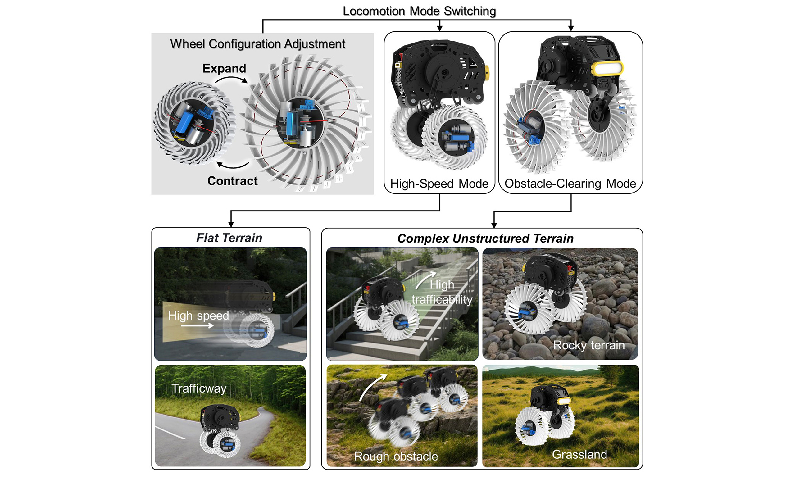
In this study, a spiral wheel with a reconfigurable shape and tunable stiffness is developed to address the limitations of conventional wheels. This wheel is designed for integration into robotic platforms to ensure reliable performance across diverse terrain [Figure 1] and offers several key advantages. First, the wheel stiffness is adjustable, enabling real-time adaptation to varying terrain conditions. Moreover, unlike conventional reconfigurable wheels that depend on multiple mechanical components, the spiral wheel can be directly fabricated via 3D printing. This approach eliminates the negative effects caused by discontinuities in the cross-sectional profile of the wheel. In addition, the use of soft materials provides effective shock absorption, substantially reducing vibration and ensuring stable locomotion over uneven terrain. Furthermore, the design features a simplified structure, consisting of a single flexible spiral body, two external motors for deformation control, and associated control components. This simplicity reduces the risk of mechanical failure and maintenance requirements, thereby lowering long-term operational costs. This study presents a unified wheel architecture that integrates the flexible nature of the wheel with the adaptive geometry of reconfigurable wheels. The design overcomes the limitations of conventional rigid-deformable or flexible wheels (i.e., excessive vibration, mechanical complexity, and high energy consumption) by using a monolithic chiral structure actuated via a rope-driven mechanism. The experimental results demonstrate that this integrated design enables a single platform to switch seamlessly between a high-stiffness, contracted configuration for stable high-speed locomotion and a low-stiffness, expanded configuration for obstacle traversal. This study outlines a promising framework for enhancing the mobility of general mobile robotic platforms.
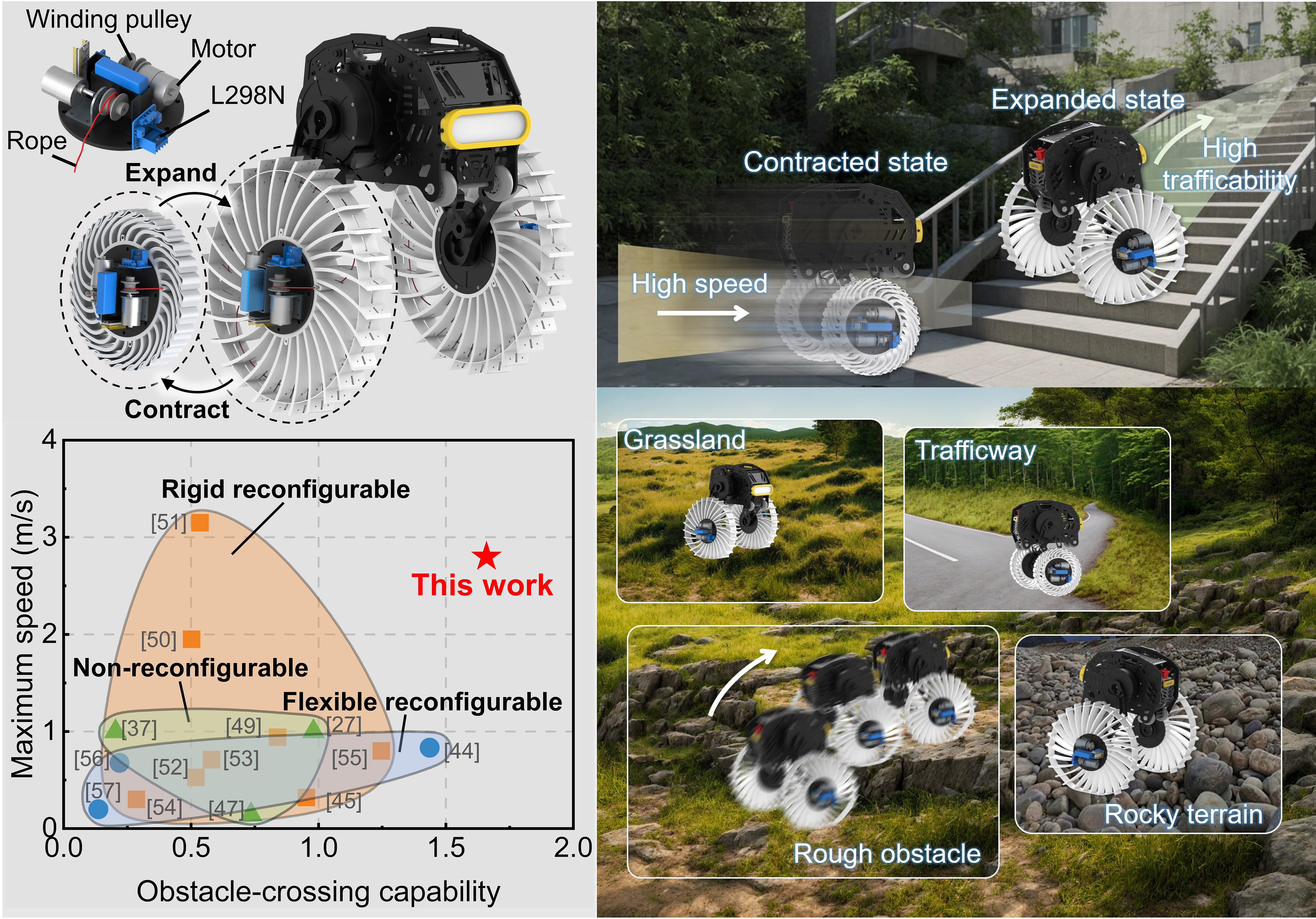
Figure 1. Design concept and locomotion performance of the proposed robot. The stiffness and locomotion-mode modulation of the spiral wheel via a rope-driven mechanism is illustrated. In the absence of rope tension, the wheels remain in their expanded, low-stiffness configuration for navigating obstacles. When the rope is tensioned, the motor contracts the wheel into a high-stiffness mode for efficient, high-speed movement. This reconfigurable design enhances the adaptability of wheeled platforms across diverse terrains, such as stairs and outdoor environments. The Ashby plot compares the proposed wheel’s performance with existing designs, demonstrating both a high obstacle-crossing capability and high-speed locomotion.
METHODS
Simulation of the contraction and compression of the spiral wheels
To simulate the contraction of the spiral wheels, a two-dimensional planar model was selected for computational efficiency. This was justified by the low thickness of the wheel relative to its radius and the minimal thickness change during deformation. The model was meshed with plane strain elements, and all six degrees of freedom of the central hole were fully constrained. To prevent local stress concentrations, the driving force of the rope was applied as a uniform pressure on the predefined regions of each spoke [Supplementary Figure 1A]. For radial compression, a rigid plane was added with a predefined contact between this plane and the wheel. The central hole remained fully constrained [Supplementary Figure 1B]. In the contracted configuration, radial compression was modeled in two steps: the first step simulated the contraction, and the second modeled the subsequent compression. Ground contact was simulated similarly to radial compression, but meshed using 3D solid elements. Here, the rigid plane was fully constrained in all six degrees of freedom. A reference point was coupled to the central hole, where a concentrated force of
Radial compression test of the spiral wheel
Radial compression tests were conducted using a universal testing machine to evaluate the radial stiffness of the spiral wheel in both expanded and contracted configurations. A custom fixture was fabricated to secure the central hole of the wheel during testing. For each configuration, the spiral wheel was mounted on the machine and subjected to compression. A video extensometer was employed to measure the compression displacement, and the applied load was recorded using the force sensor, which has a range of 0-20 kN. Loading was applied at a constant speed of 5 mm/min. The complete experimental procedures are documented in Supplementary Movies 1 and 2.
Posture characterization during robot stair-climbing
Sequential images were extracted from the test video and analyzed using ImageJ software to determine the hub height of the wheel and the lateral offset of the robot’s body during the stair-climbing test. By setting the stair height as the reference scale, the pixel distances corresponding to the wheel’s hub height and the body’s lateral offset were measured. This approach enables the accurate extraction of real-time variations in both posture parameters throughout the climbing process.
Measurement of robot acceleration during motion
An MPU6050 attitude sensor was used to measure the Z-direction acceleration of the robot equipped with the spiral wheel in both contracted and expanded configurations. The acceleration range was configured to ± 2 g. During testing, the sensor was mounted on top of the robot [Supplementary Figure 2]. Acceleration data were transmitted via Bluetooth through an ESP32 microcontroller, enabling the real-time monitoring of Z-direction acceleration variations. During testing, the sampling frequency was set to 10 Hz. The duration for the Z-axis acceleration tests when traveling in the forward direction was 10 s. The tests for forward and reverse travel presented in the Supplementary Materials lasted 6 s. In addition, all results reported in this study were obtained using unfiltered raw data to faithfully reflect the inherent vibration characteristics of the wheel structure during locomotion.
Data processing and simulation methods
All experimental and simulation data in this study were processed and plotted using Origin 2024. The commercial finite element analysis software Abaqus 6.14 was employed for finite element simulations, including structural deformation parameter optimization and radial stiffness analysis. In addition, the key evaluations in this work, including radial stiffness measurements, Z-axis acceleration testing, and fatigue testing, were repeated three times to ensure the reliability and authenticity of the data.
RESULTS AND ANALYSIS
Design of the flexible spiral wheel
The wheel-legged robot Diablo (Direct Drive Tech, China) was selected as the baseline mobile platform for implementing and evaluating the spiral wheel [Figure 1][47]. The spiral wheels mounted on the robot operate in two distinct configurations: an expanded configuration optimized for obstacle-crossing at low speed and a contracted configuration tailored for high-speed locomotion. Transitions between these configurations are actuated by external forces that modulate the relative density and stiffness of the wheel. In the expanded configuration, the wheel has low radial stiffness and a larger contact area, improving compliance and obstacle-crossing ability. By contrast, radial stiffness increases in the contracted configuration, reducing rolling resistance and enhancing traction and stability at high speeds on flat surfaces. The reconfiguration of the wheel is driven by a rope-based actuation system composed of a direct current (DC) motor, battery, winding pulleys, symmetric drive ropes, and a control module [Figure 1]. The two drive ropes are symmetrically arranged around the central hub of the wheel. When the motor rotates forward, the pulleys wind the ropes, inducing contraction of the wheel and transitioning it into the high-stiffness, contracted mode. When the motor rotates in reverse, the stored elastic potential energy in the flexible structure enables the wheel to passively return to its expanded, low-stiffness state.
Based on experimental results, the proposed spiral wheel was systematically compared with existing wheels, including rigid reconfigurable wheels[44,48-54], flexible reconfigurable wheels[43,55,56], and conventional nonreconfigurable wheels[27,37,46]. The evaluation focused on two key performance metrics: the maximum locomotion speed and obstacle-crossing capability. A definition of the obstacle-crossing capability is provided in Supplementary Text 1, and a higher value of the obstacle-crossing capability indicates the ability to surmount taller obstacles with reduced drive torque. The comparative outcomes are illustrated in the Ashby plot [Figure 1] and detailed in Supplementary Table 1. These results show that rigid wheels typically enable higher speeds on flat surfaces, whereas flexible wheels demonstrate superior obstacle negotiation. The newly proposed spiral wheel achieves a functional balance by dynamically adjusting its radial stiffness in response to terrain conditions. This adaptability allows the system to retain high-speed efficiency on smooth terrain while enhancing its obstacle-crossing performance on unstructured surfaces.
Structural parameter design
The flexible spiral wheel features a chiral geometry and consists of multiple spokes, each extending slightly beyond the outer ring to form teeth. These teeth enhance ground grip, thereby improving the ability of the robot to overcome obstacles. The three most critical structural parameters are the number of spokes, spoke thickness, and outer-ring thickness. These parameters were optimized through finite element simulations that evaluated the external force required for contraction and the degree of unevenness in the outer rim after contraction. The definition of rim unevenness is provided in Supplementary Text 2.
To determine the optimal number of spokes, simulations were conducted with the outer-ring and spoke thicknesses fixed at 2 and 6 mm, respectively, while varying the number of spokes from 20 to 32. The results presented in Figure 2A show that the external force required for contraction gradually decreases as the number of spokes increases. Local minima in rim unevenness were observed at 22 and 28 spokes. After a comprehensive evaluation, a 28-spoke configuration was selected as it yields a reduced contraction force and low postcontraction unevenness. Subsequently, a 28-spoke configuration and outer-ring thickness of 2 mm were used while performing further simulations to optimize the spoke thickness, which was varied from 4.5 to 8.5 mm. The results shown in Figure 2B indicate that the required contraction force increases with increasing spoke thickness. Considering unevenness, a nonmonotonic trend was observed as it initially decreased and then increased. The minimum rim unevenness occurred at a spoke thickness of approximately 6.5 mm, and this was selected as the optimal value. Finally, simulations were conducted to determine the optimal outer-ring thickness of the spiral wheel using a spoke thickness of 6.5 mm. The outer-ring thickness varied from 1 to 3 mm. The simulation results [Supplementary Figure 3A] indicate that the external force required for wheel contraction increases as the outer-ring thickness decreases. The unevenness exhibited a nonmonotonic trend, with local maxima and minima observed throughout the range. A relatively low unevenness was achieved at outer-ring thicknesses of 1 and 2 mm. However, the radial stiffness of the spiral wheel was insufficient at an outer-ring thickness of 1 mm, and this structure is more susceptible to wear and fracture. Therefore, an optimal outer-ring thickness of 2 mm was determined.
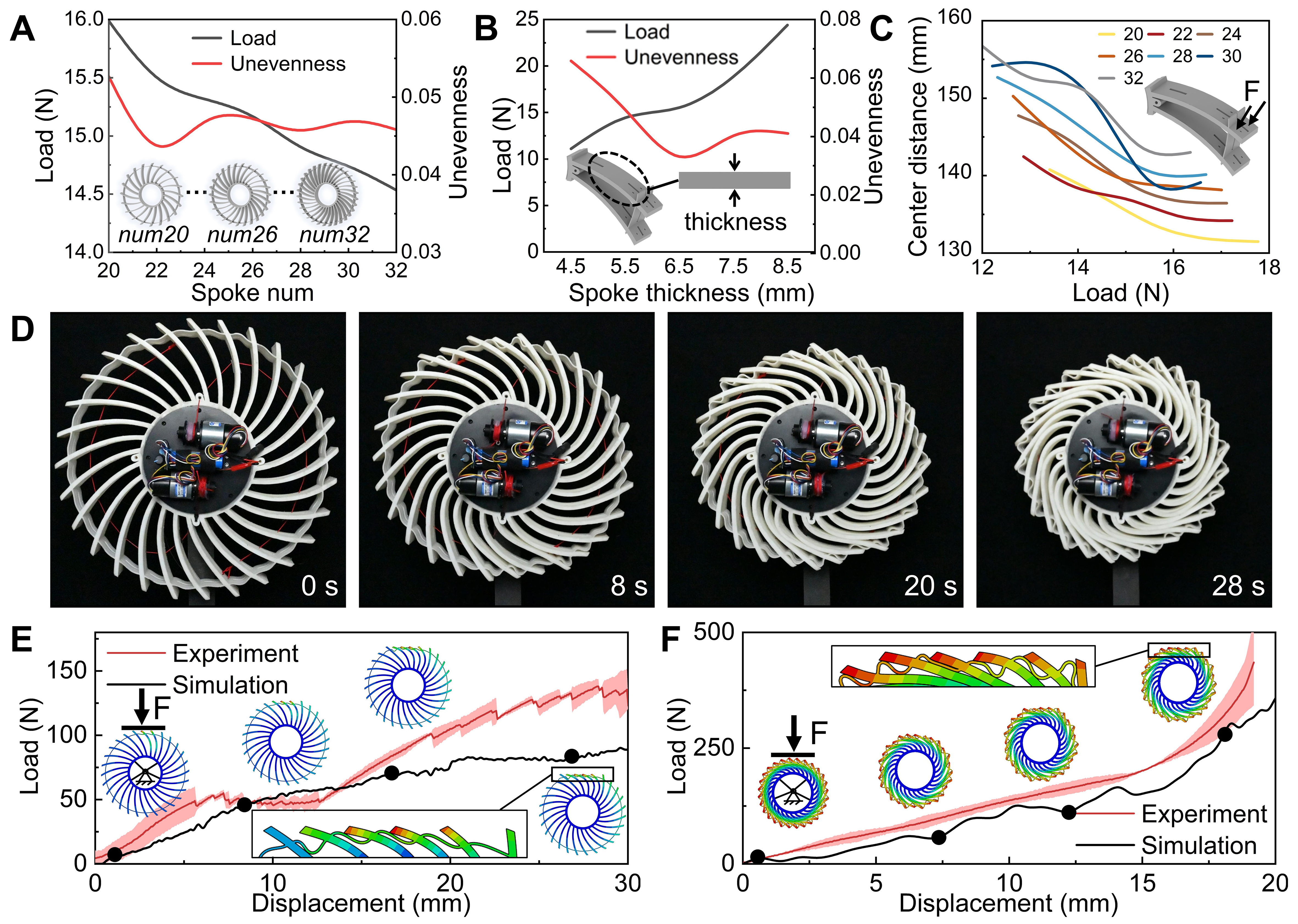
Figure 2. Structural design and mechanical testing of the spiral wheel. (A) Influence of the number of spokes on the contraction force and postcontraction outer-ring unevenness; (B) Influence of spoke thickness on the contraction force and outer-ring unevenness; (C) Contraction degree vs. applied force for wheels with different numbers of spokes, quantified by the average distance between the farthest and nearest points on the outer ring; (D) Contraction test under actuation by the external drive mechanism (photographed by the authors); (E) Comparison of experimental and simulated radial compression results for the expanded configuration; (F) Comparison of the experimental and simulated radial compression results for the contracted configuration.
Additionally, throughout the evaluation of the three structural parameters, the relationship between the contraction degree of the spiral wheel and the applied external force was analyzed. The contraction degree is defined as the average distance between the outer-ring point that is farthest from the center and the point nearest to the center after deformation. A smaller average distance indicates a greater degree of contraction, whereas a larger distance corresponds to a more expanded state. The relationship between the contraction degree and applied external force with a varied number of spokes is illustrated in Figure 2C. The corresponding results for varied spoke and outer-ring thicknesses are provided in Supplementary Figure 3B and C, respectively. In all three cases, the average distance from the center decreased as the applied force increased, indicating progressive contraction. A distinct inflection point was observed in each scenario, beyond which further increases in force resulted in minimal changes in the contraction degree. This inflection point occurs during the full contraction of the wheel, and the corresponding force represents the minimum actuation force required for complete contraction, which can serve as a key criterion for selecting the motor in the driving mechanism.
Shape reconfiguration of the spiral wheel
Following the determination of the optimal structural parameters, both simulations and contraction experiments were conducted on the spiral wheel. The results of the contraction simulation are presented in Supplementary Figure 4A. Under the applied external force, the spokes uniformly rotate in the same direction, effectively eliminating the gaps between them. This deformation results in the wheel exhibiting a reduced macroscopic diameter and increased relative density. In the simulation, the initial diameter of the spiral wheel was 43 cm, which finally contracted to approximately 27 cm, representing a reduction of approximately 37%. In the experiments, two motors, each with a maximum output torque of 1.8 N·m, were employed to drive the wheel. Conventional nylon ropes were adopted to meet the requirements of short-term experiments. However, it should be noted that this material may be replaced with higher-strength or more wear-resistant alternatives, such as coated steel wire or high-performance aramid fiber, for long-term service applications in complex and extreme environments. The complete contraction process is illustrated in Figure 2D, and a corresponding experimental video is provided in Supplementary Movie 3. The contraction was completed in 28 s, and the resulting wheel exhibited a uniform circular outer rim and increased radial stiffness, closely aligning with the simulation results. Throughout the experiment, the rotational speed of the four contraction motors was recorded, as shown in Supplementary Figure 5A. By the end of the contraction, all motor speeds stabilized at approximately 0.06 rpm. The obtained data are critical for designing the control strategy used in the contraction process. A speed-feedback-based control system was implemented, wherein the motors were commanded to stop when their feedback speed dropped below 0.06 r/min. This approach effectively prevents motor overload and potential damage.
Stiffness regulation of the spiral wheel
To compare the radial stiffness of the spiral wheel in its expanded and contracted configurations, load–displacement curves were obtained by using a universal testing machine. The compression process for the expanded configuration is shown in Supplementary Movie 1, with a total compression distance of 3 cm. The load–displacement curves obtained from the experiments and simulations are presented in Figure 2E. The results reveal a nonlinear variation in tangent stiffness (dF/du, defined as the derivative of the load F with respect to the displacement u) throughout the compression process. This behavior is attributed to the progressive increase in contact area. Initially, the compression head engages only the top of a single spoke. As it moves downward, more spokes come into contact, thereby increasing the resistance toward further compression. However, it should be noted that some discrepancies exist between the simulation and experiment due to minor manufacturing defects.
Compression tests were also conducted on the spiral wheel in its contracted configuration. The load–displacement curves from both the simulation and experiments are presented in Figure 2F. Compared to the expanded configuration, a marked increase in tangent stiffness can be observed in the contracted configuration. Under practical operating conditions, a single robot leg supports a load of 120 N. When this load was applied to the spiral wheel in the expanded configuration, the resulting radial compression displacement was 27 mm. By contrast, the compression displacement was reduced to 8 mm under the same load in the contracted configuration. This indicates that the radial stiffness of the spiral wheel increased by nearly 3.3 times after contraction. The higher radial stiffness in the contracted configuration boosts traction and load support at high speeds, while the lower stiffness and larger contact area in the expanded configuration improve terrain contact and obstacle-crossing.
Assembly of the spiral wheel on the robot
Following the integration of the spiral wheel onto the robot, a simulation analysis of the ground-contact pressure distribution was conducted. In the expanded configuration, five distinct contact points labeled a1 through a5 were identified, and the corresponding pressure values at each point are illustrated in Figure 3A. In the contracted configuration, only three contact points (a1-a3) were observed [Figure 3B]. The results indicate that ground pressure was primarily concentrated near the central hub of the wheel in the expanded configuration. By contrast, a more uniform pressure distribution was achieved in the contracted configuration. Owing to the presence of structured wheel teeth along the outer rim, contact with the ground is intermittent, leading to a periodic pressure contour. Each contact area forms a strip aligned with the width of the wheel. The grounding performance was further quantified using three key parameters: the grounding coefficient K, average grounding pressure P, and pressure skewness β. The grounding coefficient and average pressure were calculated using the methods described in Supplementary Text 3. The grounding pressure skewness was determined using[57]:
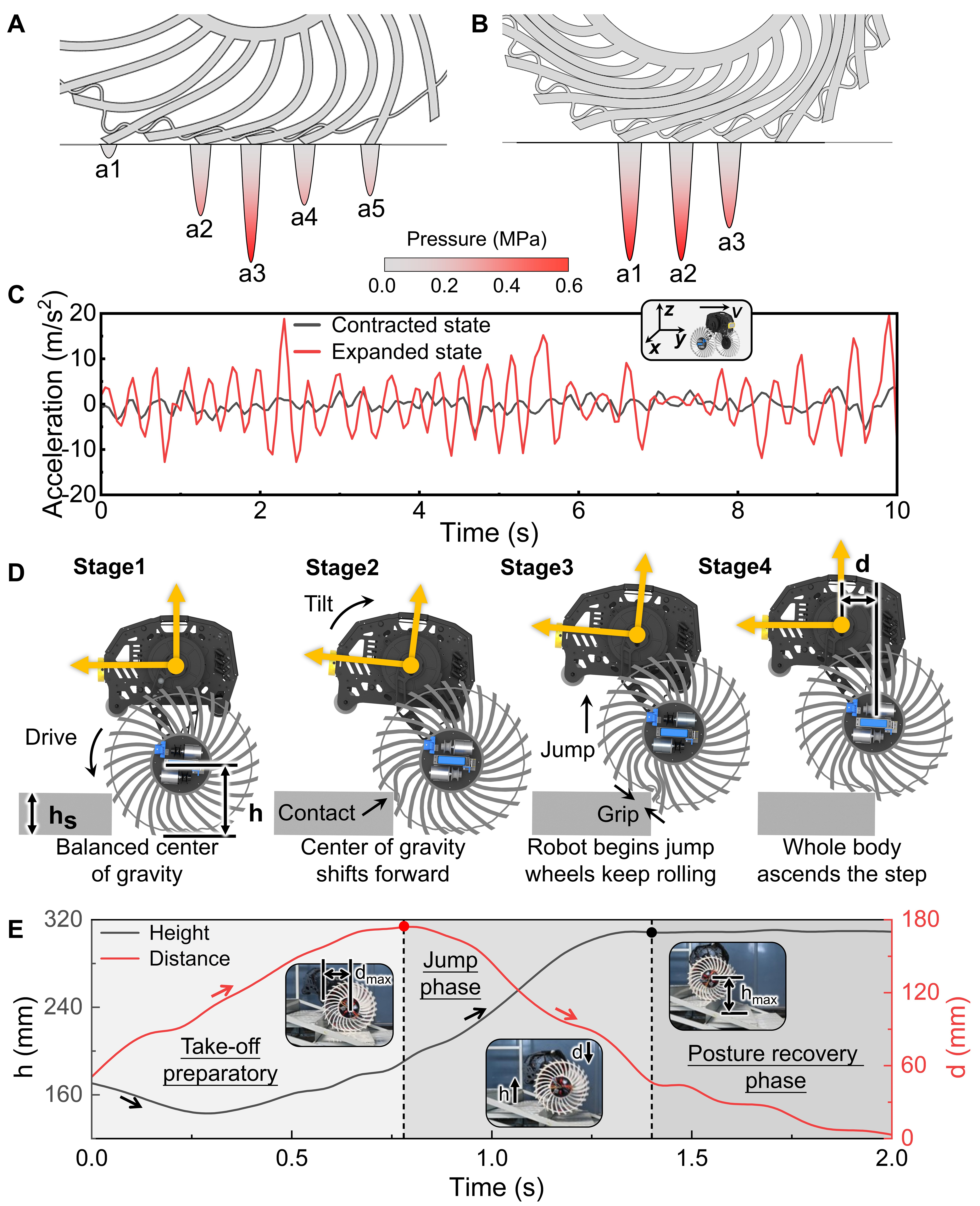
Figure 3. Ground-pressure analysis and locomotion performance of the robot with spiral wheels. (A) Ground-contact points and pressure distribution in the expanded configuration; (B) Ground-contact points and pressure distribution in the contracted configuration; (C) Z-axis acceleration comparison during high-speed travel in both configurations; (D) Stair-climbing strategy and sequence of robot movement; (E) Temporal variation of the wheel hub height and lateral body offset during stair climbing (photographed by the authors).
where Nnode denotes the number of contact nodes and Pi represents the contact pressure at node i.
The ground-contact parameters obtained from the simulation are presented in Supplementary Figure 6C, and the corresponding values are listed in Supplementary Table 2. The results show that the ground length-to-width ratio of the spiral wheel was noticeably higher in the expanded configuration, approximately 1.7 times that of the contracted configuration. While the contact width remained nearly constant in both configurations and corresponded to the design width of the wheel, the expanded configuration exhibited a greater contact length due to the increased wheel compliance. This extended contact length resulted in a higher length-to-width ratio and increased ground-contact area, thereby enhancing frictional interaction with the ground. Such an improvement contributes to better traction and supports the ability of the robot to perform tasks requiring enhanced mobility, such as obstacle negotiation.
The spiral wheel was controlled via Bluetooth after integration with the robot. Each wheel contained a control subsystem with an ESP32 microcontroller to receive control commands and drive the rotation of the motor. The control framework is illustrated in Supplementary Figure 5B. The effectiveness of this control mechanism is demonstrated in Supplementary Movie 4, which shows the transition from the expanded to the contracted configuration, and the transition process is shown in Supplementary Movie 5. During this transition, the center of gravity of the robot shifts accordingly; however, these changes do not compromise the ability of the robot to maintain its stationary balance. This capability is essential for real-world applications, as it allows the robot to autonomously switch between different spiral-wheel configurations without affecting its stability or overall operational performance.
To validate the suitability of the contracted configuration of the spiral wheel for high-speed travel, the Z-axis acceleration of the robot was measured during full-speed operation. During these tests, the robot moved along the Y-axis, and the corresponding Z-axis acceleration data is presented in Figure 3C. The results clearly show that the Z-axis acceleration in the contracted configuration (standard deviation = 1.35 m/s2) is remarkably lower than that in the expanded configuration (standard deviation = 6.20 m/s2) during full-speed motion. Moreover, the peak acceleration in the contracted configuration was approximately one-fifth of that in the expanded configuration, which exhibited higher peak acceleration signal values overall, indicating intense vertical oscillations and ride disturbances. This reflects unstable driving conditions when the spiral wheel is expanded at high speeds. By contrast, the contracted configuration yielded a noticeably smoother ride with reduced oscillations, demonstrating improved dynamic stability. To ensure consistency, comparative tests of the Z-axis acceleration were also conducted in both the forward and reverse directions. The detailed results of these tests are provided in Supplementary Figure 11, which show that the Z-axis acceleration becomes increasingly oscillatory with extended acceleration durations under both configurations of the wheel. In the contracted configuration, minimal variation was observed between forward and reverse motion. By contrast, the expanded configuration demonstrated a pronounced dependence on the moving direction of the wheel, with reverse rotation yielding noticeably lower Z-axis acceleration. These observations suggest that reverse rotation may be effectively employed as a forward locomotion strategy on locally flat terrain between obstacles.
Indoor obstacle-crossing test
An indoor obstacle-crossing test was conducted using a staircase with a height of 12 cm, which was selected to evaluate the ability of the robot to surmount a typical urban obstacle [Supplementary Figure 12]. When loaded, the spiral wheels provide a ground clearance of 16 cm at the center, and the total weight of the robot including the spiral wheels and control modules was 25 kg. The stair-climbing strategy of the robot is illustrated in Figure 3D. Due to gravitational resistance, the robot cannot climb stairs using only torque-driven rolling, and a multistage locomotion strategy is required. In State 1, the robot approaches the obstacle and detects the stair edge. In State 2, it advances a short distance while pitching its body forward, thereby shifting its center of mass toward the stair and reducing the resisting gravitational torque. This adjustment allows the spiral wheels to establish compact contact with the stair edge. In State 3, the robot initiates a jumping motion. With a maximum vertical leap height of only ~7 cm, the jump alone is insufficient to clear the stair. As a result, a continuous forward rotational torque is applied to the spiral wheels during the jump. As the robot begins to ascend, the combination of angular momentum and increased contact between the wheel edges and the stair facilitates its climbing motion. Once the center of the wheel crosses a critical height threshold relative to the edge of the stair, the robot enters State 4, successfully surmounting the obstacle. The complete stair-climbing procedure is demonstrated in Supplementary Movie 6. The movement of the robot closely follows the sequence illustrated in Figure 3D, validating the effectiveness of the proposed motion strategy and the contribution of the reconfigurable wheel.
Screenshots were captured every 0.1 s from the stair-climbing video to extract the variation in wheel-hub height and the lateral offset of the robot body. The temporal relationship between the hub height and lateral offset is illustrated in Figure 3E, and it was segmented into three distinct phases. The first phase corresponds to the jump-preparation stage, during which the lateral offset steadily increases. This shift advances the center of gravity to reduce the gravitational resistive torque during ascent. Concurrently, the body movement applies a downward force on the wheels through the linkage mechanism, causing the wheel-hub height to reach a local minimum. Following this state, increased contact between the spiral wheels and staircase enables the robot to begin rolling onto the step. Consequently, the wheel-hub height begins to increase. However, due to the limited drive torque of the hub motor, the robot is unable to ascend the stairs through rolling alone. Once the lateral offset reaches its maximum, the energy accumulation stage is complete, and the robot transitions into the second stage. During this phase, the hub height continues to increase while the lateral offset of the body decreases, returning towards its initial position. In the third stage, the robot successfully leaps onto the step. The wheel-hub height stabilizes at its maximum value, and the lateral offset gradually reduces to zero, indicating the recovery of the robot’s posture.
Outdoor mobility test
The experimental route used to evaluate the outdoor mobility of the robot is illustrated by the satellite-map trajectory in Figure 4. This route includes transitions across flat ground, grassland, a stone path, and concludes at a park with a wooden staircase. Detailed results for each terrain are provided in Supplementary Movies 7-10. During the test, the robot initially operated in the contracted configuration to traverse the flat ground, and switched to the expanded configuration before entering the unstructured terrains. The results demonstrate that the expanded wheel configuration enabled stable and effective locomotion across diverse terrains. Furthermore, the maximum travel speeds of the robot under different scenarios were measured. The robot achieved maximum speeds of 2.8 m/s on flat ground, 1.85 m/s on grassland, 1.7 m/s on the stone path, and 2.5 m/s when traversing the stairs. These speed-test results also indirectly verify the ability of the robot to navigate various terrains in different driving scenarios.
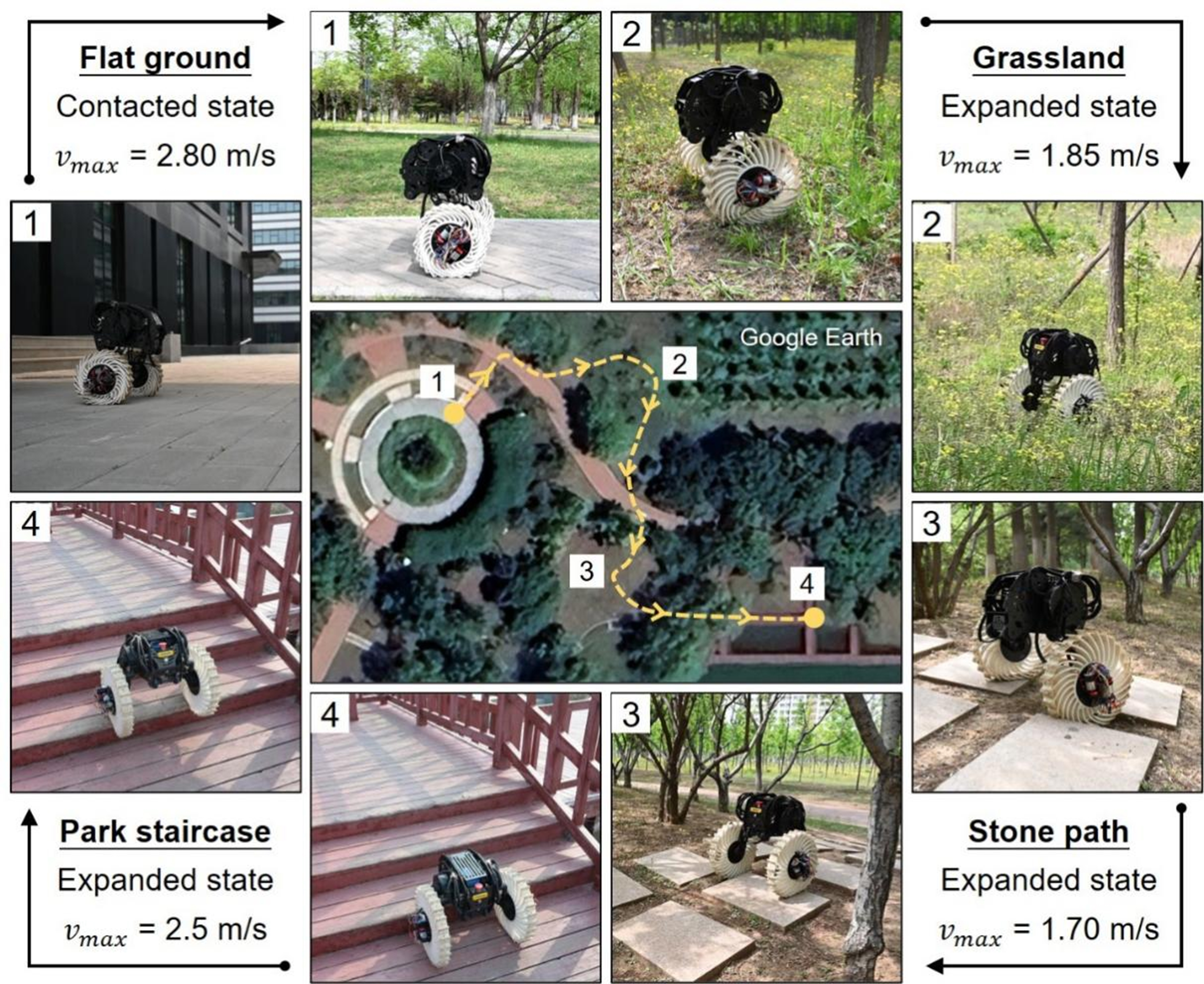
Figure 4. Outdoor locomotion test of the robot. 1. Traversing flat terrain with the spiral wheels in the contracted state. 2. Navigating grass in the expanded state. 3. Driving over a cobblestone path in the expanded state. 4. Climbing a wooden staircase in the expanded state [The map route shown in this figure was obtained using Google Earth Pro (version 7.3.3.7721, released May 28, 2020). All other elements are photographs taken during the experiments, which were captured by the authors].
CONCLUSIONS
An integrated, 3D-printed, reconfigurable spiral wheel with tunable radial stiffness was developed in this study to address the inherent mobility tradeoff between high-speed efficiency on flat ground and adaptive obstacle negotiation on complex terrains. The experimental and simulation results demonstrated that the proposed chiral structure achieved a nearly 3.3-fold increase in radial stiffness through a rope-driven contraction mechanism. In structured environments such as flat indoor surfaces, the wheel operates in its fully contracted configuration, providing increased radial stiffness and dynamic stability for high-speed travel. By contrast, when traversing unstructured or complex terrains, the wheel transitions into its expanded configuration, reducing stiffness and increasing ground compliance.
In future studies, we will integrate real-time terrain perception and adaptive control into the existing architecture by following a technical strategy considering three data streams: Inertial Measurement Unit data for monitoring the motion state and postural stability of the robot, proprioceptive feedback for capturing its structural interaction conditions, and terrain-classification methods to enable the real-time recognition of complex environments. Building upon these inputs, an adaptive morphology reconfiguration control strategy will be developed to adjust the contraction and expansion configurations of the spiral wheel in real time, thereby enabling fully autonomous shape adaptation matched to terrain characteristics.
DECLARATIONS
Acknowledgments
We would like to thank Direct Drive Tech for the technical assistance of robot hardware and control.
Authors’ contributions
Conceptualization: Duan, S.; Zhao, Z.
Methodology: He, P.; Duan, S.; Lei, H.
Investigation: He, P.; Wang, H.; Wang, P.
Funding acquisition: Wang, P.; Zhao, Z.
Project administration: Lei, H.
Writing - original draft: He, P.; Zhao, Z.
Writing - review and editing: Duan, S.; Zhao, Z.
Availability of data and materials
The original contributions presented in this study are included in the Supplementary Materials. Further inquiries can be directed to the corresponding authors.
AI and AI-assisted tools statement
During the preparation of this work, the artificial intelligence tool Gemini (Gemini 3 Flash, released 17 December 2025) was employed only for generating partial background materials in Figure 1 and graphical abstract. It exerted no influence on the research design, data acquisition, data analysis, result interpretation, or core scientific content. All authors reviewed and edited all AI-generated content and accept full responsibility for the published material.
Financial support and sponsorship
This work was supported by the National Natural Science Foundation of China (Grant Nos. 12372162 and 12302078).
Conflicts of interest
All authors declared that there are no conflicts of interest.
Ethical approval and consent to participate
Not applicable.
Consent for publication
Not applicable.
Copyright
© The Author(s) 2026.
Supplementary Materials
REFERENCES
1. Rubio, F.; Valero, F.; Llopis-Albert, C. A review of mobile robots: concepts, methods, theoretical framework, and applications. Int. J. Adv. Robot. Syst. 2019, 16, 1729881419839596.
2. Ijspeert, A. J. Biorobotics: using robots to emulate and investigate agile locomotion. Science 2014, 346, 196-203.
3. Miao, Q.; Wei, G. A comprehensive review of path-planning algorithms for planetary rover exploration. Remote. Sens. 2025, 17, 1924.
4. Makino, R.; Maeda, T. Design of a hopping leg mechanism for planetary exploration based on a genetic algorithm and a dynamic granular terrain model. Adv. Robot. 2025, 39, 1381-93.
5. Tuppathi, N.; Nizampet, M. G. Design, analysis and fabrication of rocker bogie mechanism. Int. J. Res. Anal. Rev. 2024, 11, 408-40. https://www.ijrar.org/papers/IJRARTH00245.pdf. (accessed 2026-05-09).
6. Rodríguez-Martínez, D.; Uno, K.; Sawa, K.; et al. Enabling faster locomotion of planetary rovers with a mechanically-hybrid suspension. IEEE. Robot. Autom. Lett. 2024, 9, 619-26.
7. Yang, H.; Yang, L.; Ding, L.; et al. Torque coordinated control of six-wheeled planetary rovers based on wheel–terrain interaction. IEEE. Trans. Aerosp. Electron. Syst. 2025, 61, 7754-66.
8. Casir Ricano, J. R.; Yuasa, S.; Hino, R.; Koshi, T.; Oyama, T.; Nagaoka, K. Resilient mobility of a four-wheeled planetary rover with active suspension. Acta. Astronaut. 2025, 229, 418-29.
9. Michaud, F.; Letourneau, D.; Arsenault, M.; et al. AZIMUT, a leg-track-wheel robot. In Proceedings 2003 IEEE/RSJ International Conference on Intelligent Robots and Systems (IROS 2003) (Cat. No.03CH37453), Las Vegas, USA. Oct 27-31, 2023. IEEE; 2003. pp. 2553-8.
10. Wang, J.; Liu, C.; Wei, W.; Yan, Q. Design and optimization of a reconfigurable wheel-tracked mobile robot. In Mechatronics and Automation Technology: Proceedings of the 2nd International Conference (ICMAT 2023), Wuhan, China. Oct 28-29, 2023. SAGE Publications; 2024. pp. 155-65.
11. Michaud, F.; Létourneau, D.; Arsenault, M.; et al. Multi-modal locomotion robotic platform using leg-track-wheel articulations. Auton. Robot. 2005, 18, 137-56.
12. Xuan, C.; Lu, J.; Tian, Z.; et al. Novel design of reconfigurable tracked robot with geometry-changing tracks. In 2024 IEEE/RSJ International Conference on Intelligent Robots and Systems (IROS), Abu Dhabi, United Arab Emirates. Oct 14-18, 2024. IEEE; 2024. pp. 10953-60.
13. Zhou, F.; Xu, H.; Zou, T.; Zhang, X. A wheel-track-leg hybrid locomotion mechanism based on transformable rims. In 2017 IEEE International Conference on Advanced Intelligent Mechatronics (AIM), Munich, Germany. Jul 03-07, 2017. IEEE; 2017. pp. 315-20.
14. Zhang, J.; Liu, J.; Zong, H.; et al. Bridging the gap to bionic motion: challenges in legged robot limb unit design, modeling, and control. Cyborg. Bionic. Syst. 2025, 6, 0365.
15. He, J.; Zhang, C.; Jenelten, F.; Grandia, R.; Bächer, M.; Hutter, M. Attention-based map encoding for learning generalized legged locomotion. Sci. Robot. 2025, 10, eadv3604.
16. Lee, J.; Hwangbo, J.; Wellhausen, L.; Koltun, V.; Hutter, M. Learning quadrupedal locomotion over challenging terrain. Sci. Robot. 2020, 5, eabc5986.
17. Cui, L.; Wang, S.; Zhang, J.; et al. Learning-based balance control of wheel-legged robots. IEEE. Robot. Autom. Lett. 2021, 6, 7667-74.
18. Li, Z.; Peng, X. B.; Abbeel, P.; Levine, S.; Berseth, G.; Sreenath, K. Reinforcement learning for versatile, dynamic, and robust bipedal locomotion control. Int. J. Robot. Res. 2025, 44, 840-88.
19. Nahrendra, I. M. A.; Yu, B.; Myung, H. DreamWaQ: learning robust quadrupedal locomotion with implicit terrain imagination via deep reinforcement learning. In 2023 IEEE International Conference on Robotics and Automation (ICRA), London, UK. May 29 - Jun 02, 2023. IEEE; 2023. pp. 5078-84.
20. Siegwart, R.; Nourbakhsh, I. R.; Scaramuzza, D. Introduction to autonomous mobile robots. MIT Press; 2011. https://ieeexplore.ieee.org/book/6267528. (accessed 2026-05-09).
21. Gao, X.; Li, J.; Fan, L.; et al. Review of wheeled mobile robots’ navigation problems and application prospects in agriculture. IEEE. Access. 2018, 6, 49248-68.
22. Tagliavini, L.; Colucci, G.; Botta, A.; Cavallone, P.; Baglieri, L.; Quaglia, G. Wheeled mobile robots: state of the art overview and kinematic comparison among three omnidirectional locomotion strategies. J. Intell. Robot. Syst. 2022, 106, 57.
23. Zou, M.; Zhu, J.; Wang, K.; et al. Design and mechanical behavior evaluation of flexible metal wheel for crewed lunar rover. Acta. Astronaut. 2020, 176, 69-76.
24. Wang, S.; Zou, M.; Dang, Z.; Chen, B.; Zhou, T.; Su, B. Modelling of flexible metal wheels for planetary rover on deformable terrain. Thin. Walled. Struct. 2019, 141, 97-110.
25. Sharma, G.; Tiwary, S.; Kumar, A.; Suresha Kumar, H.; Keshava Murthy, K. Systematic design and development of a flexible wheel for low mass lunar rover. J. Terramech. 2018, 76, 39-52.
26. Hong, C.; Wu, Y.; Wang, C.; et al. Wireless flow-powered miniature robot capable of traversing tubular structures. Sci. Robot. 2024, 9, eadi5155.
27. Kim, G.; Chung, H.; Cho, B. MOBINN: stair-climbing mobile robot with novel flexible wheels. IEEE. Trans. Ind. Electron. 2024, 71, 9182-91.
28. Favaedi, Y.; Pechev, A.; Scharringhausen, M.; Richter, L. Prediction of tractive response for flexible wheels with application to planetary rovers. J. Terramech. 2011, 48, 199-213.
29. Chung, G.; Quang, H. L.; Kim, J. H.; Yoo, J.; Seol, S. K.; Park, Y. Bioinspired, rapidly responsive magnetically tunable stiffness metamaterials. Adv. Mater. 2025, 37, e2505880.
30. Zhou, S.; Li, Y.; Wang, Q.; Lyu, Z. Integrated actuation and sensing: toward intelligent soft robots. Cyborg. Bionic. Syst. 2024, 5, 0105.
31. Wei, Y.; Lee, K. CLAW: cycloidal legs-augmented wheels for stair and obstacle climbing in mobile robots. IEEE/ASME. Trans. Mechatron. 2025, 30, 1536-46.
32. Hongo, K.; Kito, T.; Kamikawa, Y.; Kinoshita, M.; Kawanami, Y. Development of a compact robust passive transformable omni-ball for enhanced step-climbing and vibration reduction. In 2024 IEEE/RSJ International Conference on Intelligent Robots and Systems (IROS), Abu Dhabi, United Arab Emirates. Oct 14-18, 2024. IEEE; 2024. pp. 4098-105.
33. Zarrouk, D.; Yehezkel, L. Rising STAR: a highly reconfigurable sprawl tuned robot. IEEE. Robot. Autom. Lett. 2018, 3, 1888-95.
34. Zhang, H.; Zhu, Y.; Yang, J.; Yang, C.; Zhao, J. A bioinspired paddle-wheeled leg amphibious robot with environment-adaptive autonomously. IEEE/ASME. Trans. Mechatron. 2025, 30, 15-26.
35. Mertyüz, İ.; Tanyıldızı, A. K.; Taşar, B.; Tatar, A. B.; Yakut, O. FUHAR: a transformable wheel-legged hybrid mobile robot. Robot. Auton. Syst. 2020, 133, 103627.
36. Mardani, A.; Ebrahimi, S.; Alipour, K. 6AP wheel: a new transformable robotic wheel for traction force improvement and halting avoidance of a UGV on soft terrains. Mech. Based. Des. Struct. Mach. 2022, 50, 3370-85.
37. Sun, J.; Lerner, E.; Tighe, B.; Middlemist, C.; Zhao, J. Embedded shape morphing for morphologically adaptive robots. Nat. Commun. 2023, 14, 6023.
38. Liu, J.; Pang, Z.; Li, Z.; et al. An origami-wheeled robot with variable width and enhanced sand walking versatility. Thin. Walled. Struct. 2025, 206, 112645.
39. Zhang, S.; Yao, J.; Wang, Y.; Liu, Z.; Xu, Y.; Zhao, Y. Design and motion analysis of reconfigurable wheel-legged mobile robot. Def. Technol. 2022, 18, 1023-40.
40. Cao, R.; Gu, J.; Yu, C.; Rosendo, A. OmniWheg: an omnidirectional wheel-leg transformable robot. In 2022 IEEE/RSJ International Conference on Intelligent Robots and Systems (IROS), Kyoto, Japan. Oct 23-27, 2022. IEEE; 2022. pp. 5626-31.
41. Lee, D. Y.; Kim, J. K.; Sohn, C. Y.; Heo, J. M.; Cho, K. J. High-load capacity origami transformable wheel. Sci. Robot. 2021, 6, eabe0201.
42. Yoo, K. Y.; Kim, S.; Park, I.; Yoon, H.; Kim, H. S.; Seo, T. Disturbance torque observer-based variable impedance control for compliant stair-descending of transformable wheel mechanism. Mech. Mach. Theory. 2024, 194, 105590.
43. Lee, J. Y.; Han, S.; Kim, M.; et al. Variable-stiffness-morphing wheel inspired by the surface tension of a liquid droplet. Sci. Robot. 2024, 9, eadl2067.
44. Zheng, C.; Sane, S.; Lee, K.; Kalyanram, V.; Lee, K. α-WaLTR: adaptive wheel-and-leg transformable robot for versatile multiterrain locomotion. IEEE. Trans. Robot. 2023, 39, 941-58.
45. Park, I.; Yoon, H.; Kim, S.; Kim, H. S.; Seo, T. Review on transformable wheel: mechanism classification and analysis according to mechanical complexity. Int. J. Precis. Eng. Manuf. 2025, 26, 737-55.
46. Godden, T.; Mulvey, B. W.; Redgrave, E.; Nanayakkara, T. PaTS-wheel: a passively-transformable single-part wheel for mobile robot navigation on unstructured terrain. IEEE. Robot. Autom. Lett. 2024, 9, 5512-9.
47. Guo, T.; Liu, J.; Liang, H.; et al. Design and dynamic analysis of jumping wheel-legged robot in complex terrain environment. Front. Neurorobot. 2022, 16, 1066714.
48. Bai, L.; Guan, J.; Chen, X.; Hou, J.; Duan, W. An optional passive/active transformable wheel-legged mobility concept for search and rescue robots. Robot. Auton. Syst. 2018, 107, 145-55.
49. Sun, T.; Xiang, X.; Su, W.; Wu, H.; Song, Y. A transformable wheel-legged mobile robot: design, analysis and experiment. Robot. Auton. Syst. 2017, 98, 30-41.
50. She, Y.; Hurd, C. J.; Su, H. J. A transformable wheel robot with a passive leg. In 2015 IEEE/RSJ International Conference on Intelligent Robots and Systems (IROS), Hamburg, Germany. Sep 28 - Oct 02, 2015. IEEE; 2015. pp. 4165-70.
51. Xu, Q.; Xu, H.; Xiong, K.; Zhou, Q.; Guo, W. Design and analysis of a Bi-directional transformable wheel robot trimode. In 2021 IEEE/RSJ International Conference on Intelligent Robots and Systems (IROS), Prague, Czech Republic. Sep 27 - Oct 01, 2021. IEEE; 2021. pp. 8396-403.
52. Chou, J. J.; Yang, L. S. Innovative design of a claw-wheel transformable robot. In 2013 IEEE International Conference on Robotics and Automation, Karlsruhe, Germany. May 06-10, 2013. IEEE; 2013. pp. 1337-42.
53. Lee, Y.; Ryu, S.; Won, J. H.; Kim, S.; Kim, H. S.; Seo, T. Modular two-degree-of-freedom transformable wheels capable of overcoming obstacle. IEEE. Robot. Autom. Lett. 2022, 7, 914-20.
54. Kim, Y.; Jung, G.; Kim, H.; Cho, K.; Chu, C. Wheel transformer: a wheel-leg hybrid robot with passive transformable wheels. IEEE. Trans. Robot. 2014, 30, 1487-98.
55. Lai, Y.; Zang, C.; Luo, G.; et al. An agile multimodal microrobot with architected passively morphing wheels. Sci. Adv. 2024, 10, eadp1176.
56. Lee, D. Y.; Kim, S. R.; Kim, J. S.; Park, J. J.; Cho, K. J. Origami wheel transformer: a variable-diameter wheel drive robot using an origami structure. Soft. Robot. 2017, 4, 163-80.
Cite This Article
How to Cite
Download Citation
Export Citation File:
Type of Import
Tips on Downloading Citation
Citation Manager File Format
Type of Import
Direct Import: When the Direct Import option is selected (the default state), a dialogue box will give you the option to Save or Open the downloaded citation data. Choosing Open will either launch your citation manager or give you a choice of applications with which to use the metadata. The Save option saves the file locally for later use.
Indirect Import: When the Indirect Import option is selected, the metadata is displayed and may be copied and pasted as needed.
About This Article
Copyright

Data & Comments
Data
0


Comments
Comments must be written in English. Spam, offensive content, impersonation, and private information will not be permitted. If any comment is reported and identified as inappropriate content by OAE staff, the comment will be removed without notice. If you have any queries or need any help, please contact us at [email protected].