

fig1
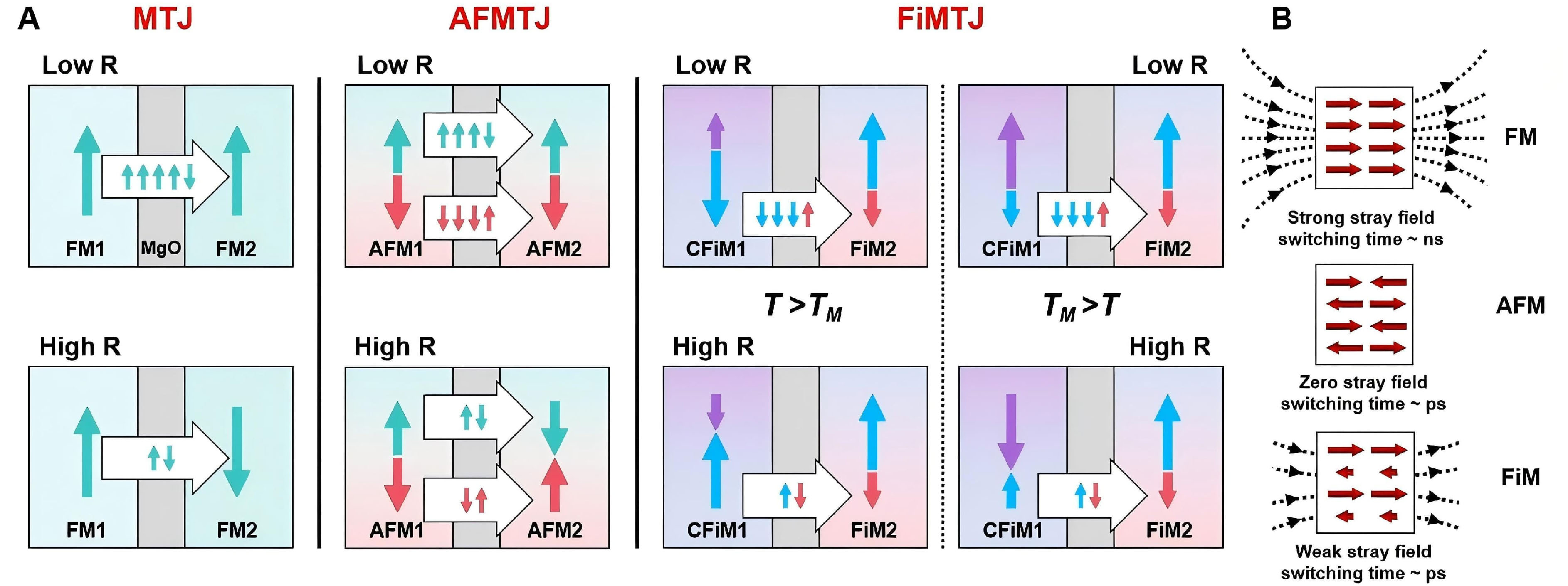
Figure 1. Schematics of different types of tunnel junctions. (A) Schematics of a conventional MTJ where two ferromagnetic (FM) electrodes are separated by a tunnel barrier. Conduction (indicated by block arrows) between the left and right FM electrodes for parallel and antiparallel magnetization (indicated by different colored arrows). Schematics of an antiferromagnetic tunnel junction (AFMTJ) with two AFM electrodes. Schematics of our ferrimagnetic tunnel junction (FiMTJ) with a compensated ferrimagnetic electrode (CFiM1) and another ferrimagnetic electrode (FiM2). Tunneling behavior at temperatures below and above TM is illustrated; (B) Schematic comparison of magnetic configuration, stray fields, and spin dynamics of FM, AFM, and FiM. MTJ: Magnetic tunnel junction.