

fig8
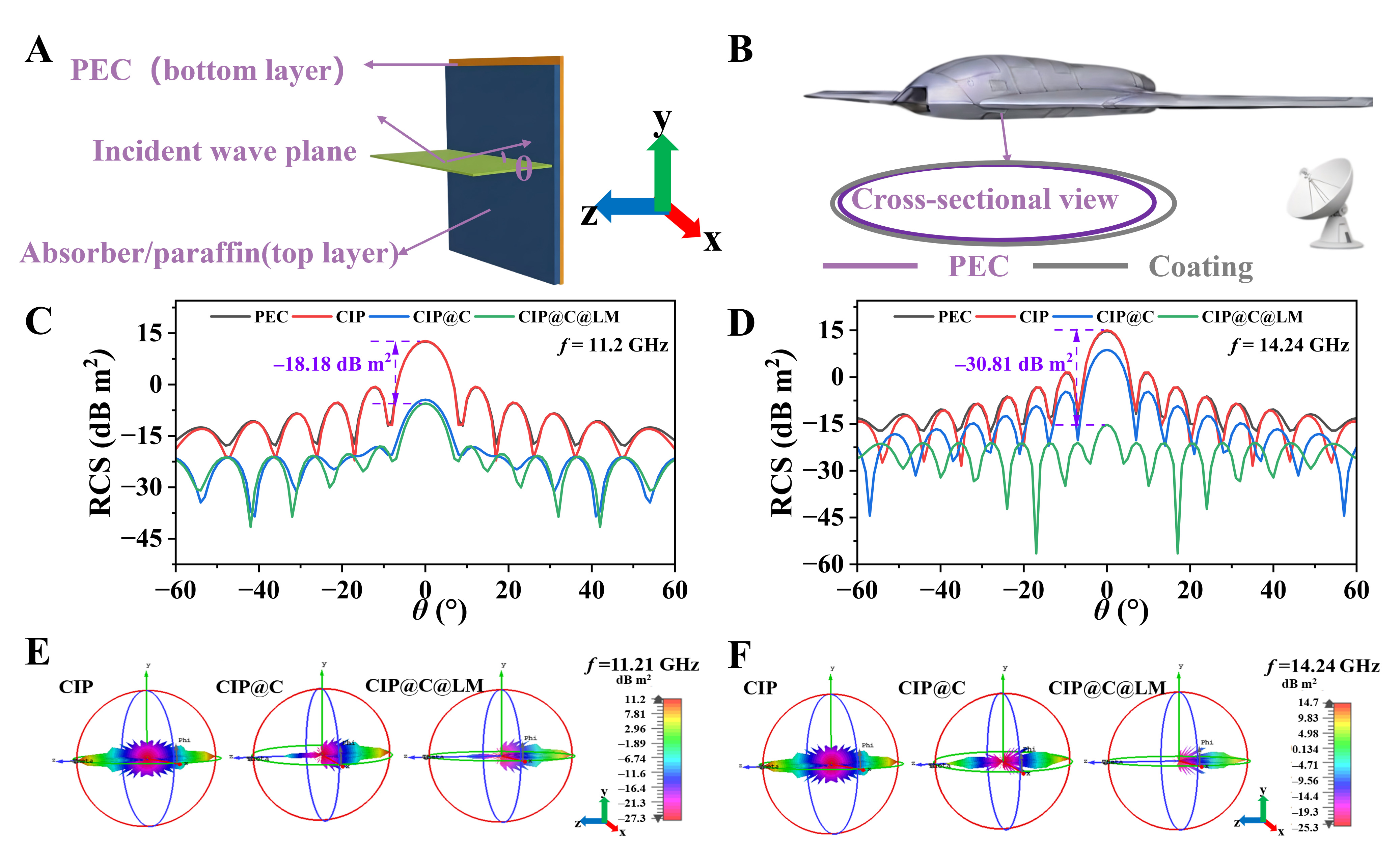
Figure 8. Radar cross-section (RCS) simulation of the composite absorbers. (A) Theta polarization model, (B) Drone model with ultra-wideband EMW absorption performance; (C and D) RCS simulation curves of PEC in the test range of -60.0° < θ ≤ 60.0° at 11.21 GHz and 14.24 GHz, (E and F) CST far-field simulation results of CIP, CIP@C and CIP@C@LM. CIP: Carbonyl iron powder; LM: liquid metal; EMW: electromagnetic wave; PEC: perfect electric conductor; RCS: radar cross-section; CST: computer simulation technology.