

fig10
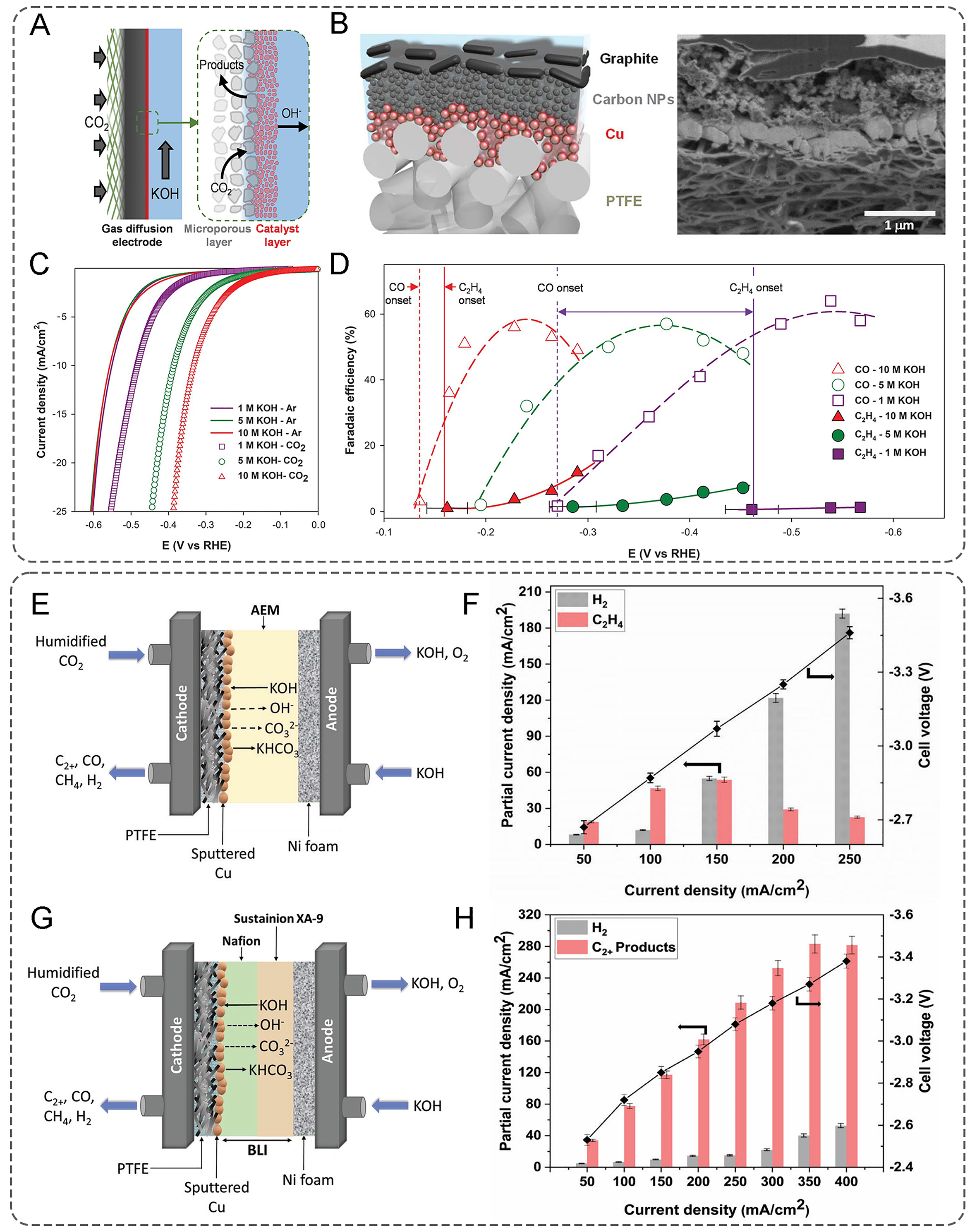
Figure 10. (A) Schematic of the cathode portion of a gas diffusion electrode for CO2; (B) Schematic illustration and Cross-sectional SEM image of the graphite/carbon NPs/Cu/PTFE electrode, (C) LSV scan in various KOH electrolytes; (D) C2H4 and CO FEs with increasing KOH concentrations. (A-D) Reproduced with permission[10]. Copyright 2018, AAAS; eCO2RR using Sustainion X37-50 Grade RT AEM and 1 M KOH as anolyte: (E) schematic diagram of the MEA system; (F) partial current density of C2H4 and H2 and cell voltage at different current density; (G) schematic diagram of the MEA system using BLI-25:25 on Cu catalyst in reverse bias mode; (H) partial current density toward C2+ and H2 at different current density; using 100 mL of 1 M KOH as anolyte. (E-H) Reproduced with permission[172]. Licensed under CC BY 4.0. LSV: Linear sweep voltammetry; FEs: Faradaic efficiencies; eCO2RR: Electrocatalytic CO2 reduction reaction; AEM: Anion exchange membrane; MEA: Membrane electrode assembly; BLI: Bilayer ionomer. PTFE: polytetrafluoroethylene.