




Synergistic Strengthening and toughening in L-DED CoCrNi medium-entropy alloys: roles of dislocations and core-shell heterostructures
 0
0 Abstract
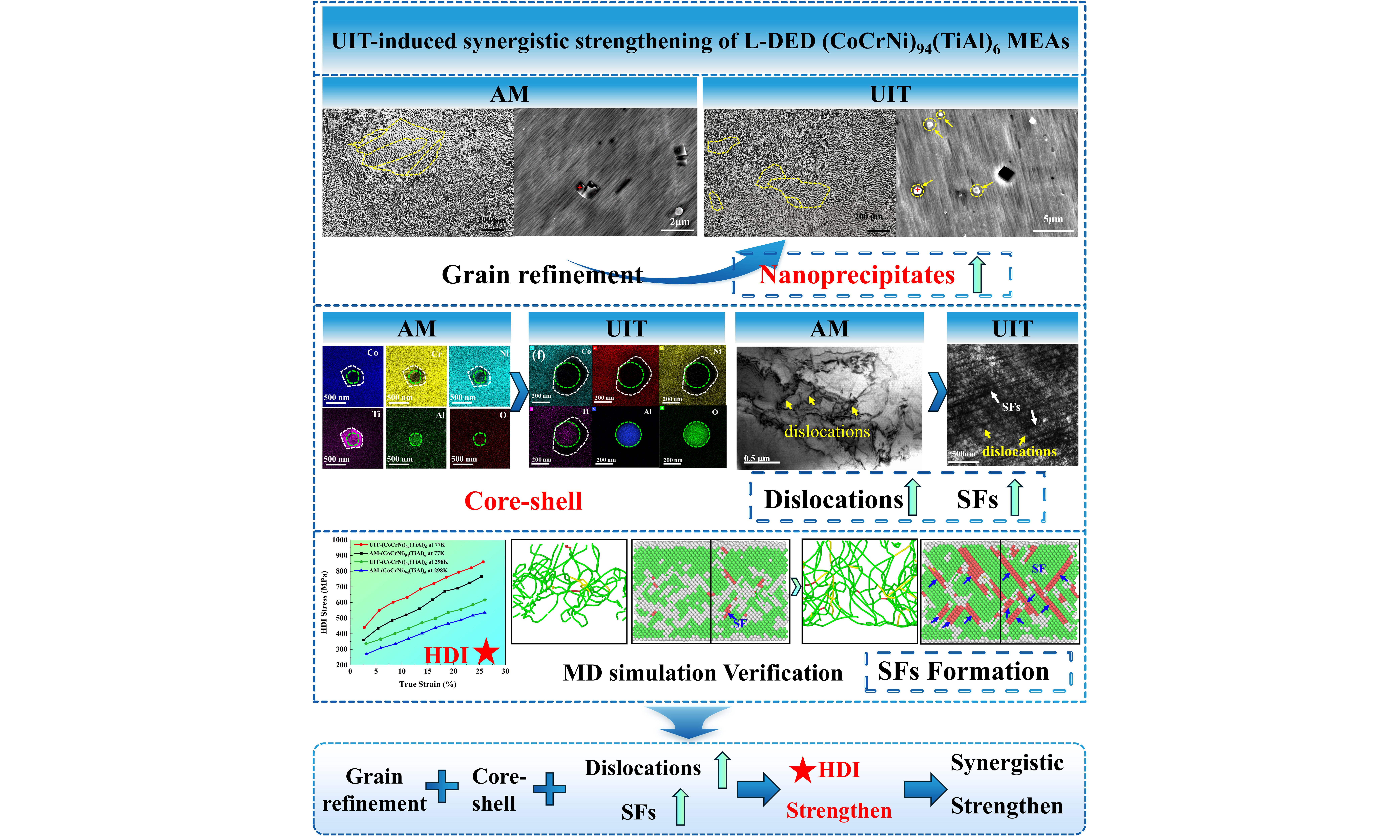
To overcome the strength bottleneck of CoCrNi medium-entropy alloys (MEAs), this work systematically investigates the influence of Ti and Al addition strategies and ultrasonic impact treatment (UIT) on CoCrNi MEAs. Results indicate that the addition of TiAl master alloy promotes uniform dispersion of Ti-Al-O composite precipitates with a core-shell heterostructure, achieving synergistic enhancement of strength and plasticity. The alloy exhibits a yield strength (YS) of 589.1 MPa, an ultimate tensile strength of 973.5 MPa, and elongation of 34.4%. Further application of UIT refines the grain structure, induces high-density dislocations and stacking faults, and optimizes precipitate morphology. As a result, YS is enhanced to 692.7 MPa at 298 K and 997.7 MPa at 77 K, improvements of 17.6% and 40.6% compared to the as-deposited alloy. However, this strengthening is accompanied by a reduction in elongation, reflecting a typical strength-ductility trade-off. Despite the reduced ductility, UIT-treated alloy exhibits excellent strength at 77 K, highlighting its potential for cryogenic engineering applications where high strength is prioritized. Molecular dynamics simulations reveal the dynamic evolution of dislocation nucleation and stacking faults under impact loading. Quantitative analysis based on load-unload-reload testing indicates that heterogeneous deformation-induced strengthening provides a dominant contribution to the overall flow stress. The microstructural origin of this strengthening effect stems from the long-range stress fields and short-range obstruction effects arising from high-density dislocations, nanoprecipitates, and stacking faults introduced by UIT. These features continuously impede dislocation motion, thereby significantly enhancing deformation resistance.
Keywords
INTRODUCTION
CoCrNi medium-entropy alloys (MEAs) with a face-centered cubic structure have attracted considerable attention due to their excellent ductility, fracture resistance, and remarkable mechanical stability at cryogenic temperatures[1,2]. These outstanding properties make them promising candidates for applications in extreme environments such as aerospace and cryogenic engineering[3,4]. Nevertheless, their relatively low yield strength (YS) limits their load-bearing capacity, which has become a critical bottleneck for further applications[5-7].
Alloying is an effective approach for strengthening CoCrNi MEAs[8-10]. Liu et al.[11] employed Ti and C microalloying to refine grain size and simultaneously enhance strength and plasticity of CoCrNi MEAs. Chang et al.[12] achieved about a 33% increase in YS via solid solution strengthening and grain boundary (GB) refinement by adding 3 at.% W to CoCrNi MEAs, while maintaining good ductility. Additionally, Ti and Al addition is effective for precipitation strengthening[13], as their strong negative mixing enthalpy with Ni and Co promotes nanoscale precipitation to impede dislocation motion. Zhao et al.[14] demonstrated that co-adding Ti and Al induces nanoscale L12 precipitates with heterogeneous distribution and shifts deformation mechanisms from mechanical twinning to stacking fault-dominated deformation, thereby achieving superior comprehensive mechanical properties. In this study, all alloy compositions are expressed in atomic percent (at.%). The Ti-only and Al-only alloys each contain 3 at.% of the respective solute element and serve as single-element reference compositions. In contrast, the three Ti-Al co-added alloys contain a fixed total Ti+Al content of 6 at.%, enabling a direct comparison among different Ti-Al co-addition strategies. Despite these advances, the practical implementation of Ti and Al alloying still faces significant challenges. Al tends to segregate on powder surfaces during mixing due to its lower density, resulting in an inhomogeneous distribution of components[15], and is prone to burn-off during additive manufacturing (AM), disrupting the Ti/Al ratio and affecting precipitate formation and stability, ultimately causing performance fluctuations[16,17]. Consequently, the influence of different Ti and Al addition strategies on microstructure and mechanical properties has not been systematically clarified. In particular, systematic comparisons of Ti-only, Al-only, mixed elemental Ti+Al, partial TiAl master alloy, and full TiAl master alloy addition strategies under identical L-DED processing conditions remain limited. In the present experimental design, the Ti-only and Al-only alloys serve as 3 at.% single-element reference compositions, whereas the three Ti-Al co-added alloys contain a constant total Ti+Al content of 6 at.% and are used to compare different Ti-Al addition routes. This design provides reference points for evaluating the effects of individual Ti and Al additions while enabling a controlled comparison among the different Ti-Al co-addition strategies.
Multi-energy field regulation technology provides a novel approach to overcoming the aforementioned bottlenecks and improving material properties[18]. For instance, laser cladding has been widely employed to fabricate wear-resistant composite coatings on titanium alloys, with recent studies demonstrating that multi-scale reinforcement architectures can significantly enhance surface hardness and tribological performance[19]. As an efficient surface modification process, ultrasonic impact treatment (UIT) achieves multi-scale microstructure refinement, dislocation proliferation and residual stress optimization, thereby improving comprehensive mechanical properties[20,21]. Xu et al.[22] demonstrated that UIT induces severe surface plastic deformation in Hastelloy X, leading to a significant increase in dislocation density and dislocation pile-ups, while fractured columnar grains provide nucleation sites for recrystallization. Wang et al.[23] further revealed that UIT induces extensive substructure formation in deeper regions, serving as recrystallization nucleation sites during subsequent thermal cycling or heat treatment, promoting grain refinement and transformation of columnar to equiaxed grains. However, previous studies on UIT mainly reported grain refinement, residual stress modification, or hardness improvement. The interaction between UIT and TiAl-alloyed CoCrNi MEAs with core-shell nanoprecipitates - particularly regarding precipitate refinement, dislocation accumulation, stacking fault formation, and heterogeneous deformation-induced strengthening - remains unexplored. Moreover, the atomic-scale mechanisms of UIT-induced dislocation and stacking fault evolution have not been revealed.
Combining alloying with UIT fully exploits the precipitation strengthening potential of Ti and Al while compensating for microstructural defects caused by powder mixing inhomogeneity and element burn-off, creating synergistic effects from precipitation strengthening, grain refinement strengthening and dislocation strengthening. It is worth noting that our previous work focused solely on the as-deposited (CoCrNi)94(TiAl)6 MEA and its strengthening mechanisms. The present study substantially extends that investigation in four critical aspects: systematic comparison of five different Ti/Al addition strategies to identify the optimal approach; application of UIT post-treatment as a second-stage optimization; comprehensive evaluation of mechanical performance at cryogenic temperature (77 K); and molecular dynamics (MD) simulations to reveal the atomic-scale mechanisms of UIT-induced dislocation and stacking fault evolution.
Therefore, this work aims to develop a synergistic strengthening strategy for CoCrNi MEAs by combining controlled Ti/Al addition with UIT. The study first systematically investigates the effects of different Ti and Al addition methods on microstructure and mechanical properties by using Ti-only and Al-only alloys as single-element reference compositions and comparing three Ti-Al co-added alloys with a constant total Ti+Al content of 6 at.%. Subsequently, the optimized alloy is subjected to UIT to further tailor its microstructure. By integrating experimental characterization with MD simulations, this work elucidates the underlying mechanisms of dislocation evolution, stacking fault formation, and heterogeneous deformation-induced strengthening, providing insights into the design of high-performance MEAs with enhanced strength-ductility synergy.
EXPERIMENTAL
To systematically evaluate the effects of individual Ti and Al additions and different Ti-Al co-addition strategies, five alloy compositions were designed: (1) Ti-only: (CoCrNi)97Ti3; (2) Al-only: (CoCrNi)97Al3; (3) mixed elemental Ti+Al: (CoCrNi)94Ti3Al3; (4) partial TiAl master alloy: (CoCrNi)94(TiAl)3Ti1.5Al1.5; and (5) full TiAl master alloy: (CoCrNi)94(TiAl)6. The Ti-only and Al-only alloys each contain 3 at.% of a single solute element and were used as reference compositions, whereas the latter three Ti-Al co-added alloys contain a constant total Ti+Al content of 6 at.% to enable comparison of different co-addition routes. For the elemental-powder addition groups, the CoCrNi, Ti, and Al powders were supplied by AVIMetal Powder Metallurgy Technology Co., Ltd. The Ti and Al powders had a purity of 99.9%. After being mixed, the particle size range is from 33 to 133 μm. The powder is mechanically mixed for 8 hours using all-directional planetary ball mill equipment (QM-QX2L) to ensure uniformity. For the laser-directed energy deposition (L-DED) process, initial powder employed was CoCrNi MEAs with an equiatomic ratio of 1:1:1 (at.%) and TiAl master alloy powders with a Ti:Al ratio of 1:1 (at.%). The measured oxygen content in the mixed powders was 254 ppm. The particle size distribution ranged from 33 to 133 μm, and the L-DED was performed under an argon atmosphere. The detailed powder morphology, elemental distribution, X-ray diffraction (XRD) characterization, and the actual chemical composition of the as-deposited (CoCrNi)94(TiAl)6 alloy have been systematically reported in our previous work[24], which employed the same feedstock powders and identical L-DED processing parameters. The deposited alloy composition was confirmed to be close to the nominal composition, with only minor oxygen pickup during the L-DED process. Specimens were fabricated using a commercial L-DED system with a 4,000 W coaxial powder-feeding fiber laser. The processing parameters were consistent for both as-deposited and UIT-treated samples: laser power of 1,200 W, spot diameter of 2 mm, scanning speed of 600 mm/min, hatch spacing of 0.8 mm, and layer overlap ratio of 50%. The scanning direction of adjacent layers was rotated by 90° using a raster scanning strategy [Figure 1A]. Post-treatment was carried out using a UIT-300 device, comprising an impact tool and a power supply [Figure 1B]. The impact frequency was set to 17 kHz with an amplitude of 20 μm, using a reciprocating impact path aligned with laser scanning path for 120 s, four-head impact, and impact head travel speed of 5 mm/s. An S-shaped reciprocal impact path was applied on the coating surface. Notably, the UIT treatment was applied to the entire gauge section of the subsequent dog-bone tensile samples, ensuring uniform surface modification across the entire tensile testing region.
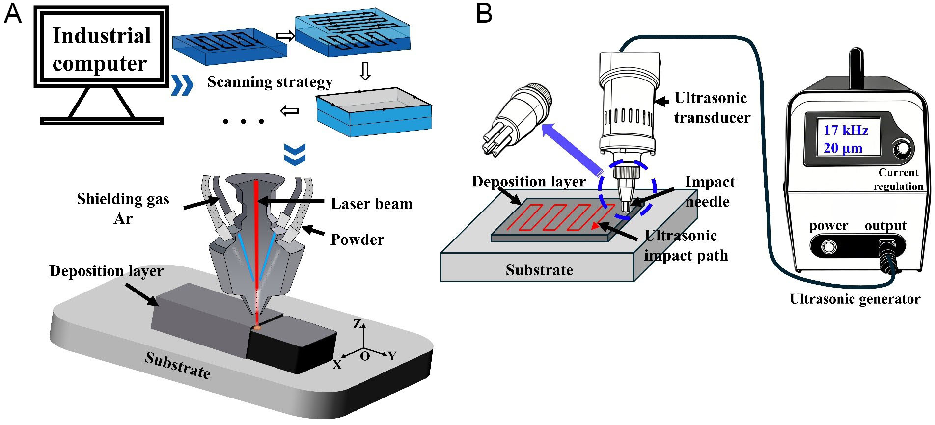
Figure 1. Schematic diagram. (A) laser directional energy deposition; (B) UIT. UIT: Ultrasonic impact treatment.
Mechanical properties were tested using a SUNS UTM4304GD universal testing machine at 298 K and 77 K. Low-temperature tensile tests employed a contact-type cryogenic extensometer for strain measurement. Load-unload-reload (LUR) tests were conducted at both 298 K and 77 K, with specimen dimensions identical to those used for uniaxial tensile tests. A load-unload cycle was performed for every 1% strain increment, with loading controlled by strain at 0.4 mm/min and unloading controlled by force at 100 N/min until a terminal force of 50 N was reached. Microstructure and grain morphology were observed using a ZEISS Gemini SEM 300 scanning electron microscope (SEM). Electron backscatter diffraction (EBSD) analysis was performed at an accelerating voltage of 20 kV, a sample tilt angle of 70°, a working distance of approximately 15 mm, and a step size of 0.2 μm. Grain size distributions were calculated using the equivalent circle diameter method. Transmission electron microscope (TEM) specimens were mechanically thinned to 50 μm, punched into 3 mm discs, and then ion beam thinned. Phase structure and chemical composition were characterized using an FEI Talos F200X TEM.
In MD simulations[25,26], a polycrystalline model was constructed using Voronoi tessellation method implemented in Atomsk[27-30]. Periodic boundary conditions were imposed in all three dimensions to mimic an infinite crystalline matrix, with grain sizes ranging from 10 to 20 nm. (CoCrNi)94(TiAl)6 MEAs utilized an embedded atom method potential[31-33] that accurately describes energy, defect behavior, plastic deformation mechanisms, and chemical characteristics. The visualization and identification of atomic arrangements were performed using Ovito software[34-36], while atomic-scale simulations and calculations were carried out using LAMMPS software[37-39]. Prior to simulation, an energy minimization procedure was conducted on the initial configuration to eliminate non-physical configurations.
RESULTS AND DISCUSSIONS
Adding Ti and Al effectively enhances the performance of CoCrNi-based MEAs. The microstructure of CoCrNi-based MEAs after alloying element addition is shown in Figure 2. Figure 2A and B displays XOY and XOZ planes of AM (CoCrNi)97Ti3 MEAs. The XOY plane exhibits a typical columnar structure with lamellar substructures, distinct GBs and no significant defects. On the XOZ surface, columnar grain morphology varies with viewing angle, but overall structural integrity remains good. Figure 2C and D shows XOY and XOZ planes in AM (CoCrNi)97Al3 MEAs. Numerous cracks distributed along GBs appear in XOY structure, and columnar grains appear fragmented. In contrast, both crack quantity and size are slightly reduced, while columnar grain content remains comparable to that of (CoCrNi)97Ti3 in the XOZ surface. Figure 2E-H illustrates XOY and XOZ planes of (CoCrNi)94Ti3Al3 MEAs and (CoCrNi)94(TiAl)3Ti1.5Al1.5 MEAs. Both alloys exhibit a larger columnar crystal area, with finer and denser lamellar structures compared to (CoCrNi)97Ti3, and no cracks or defects.
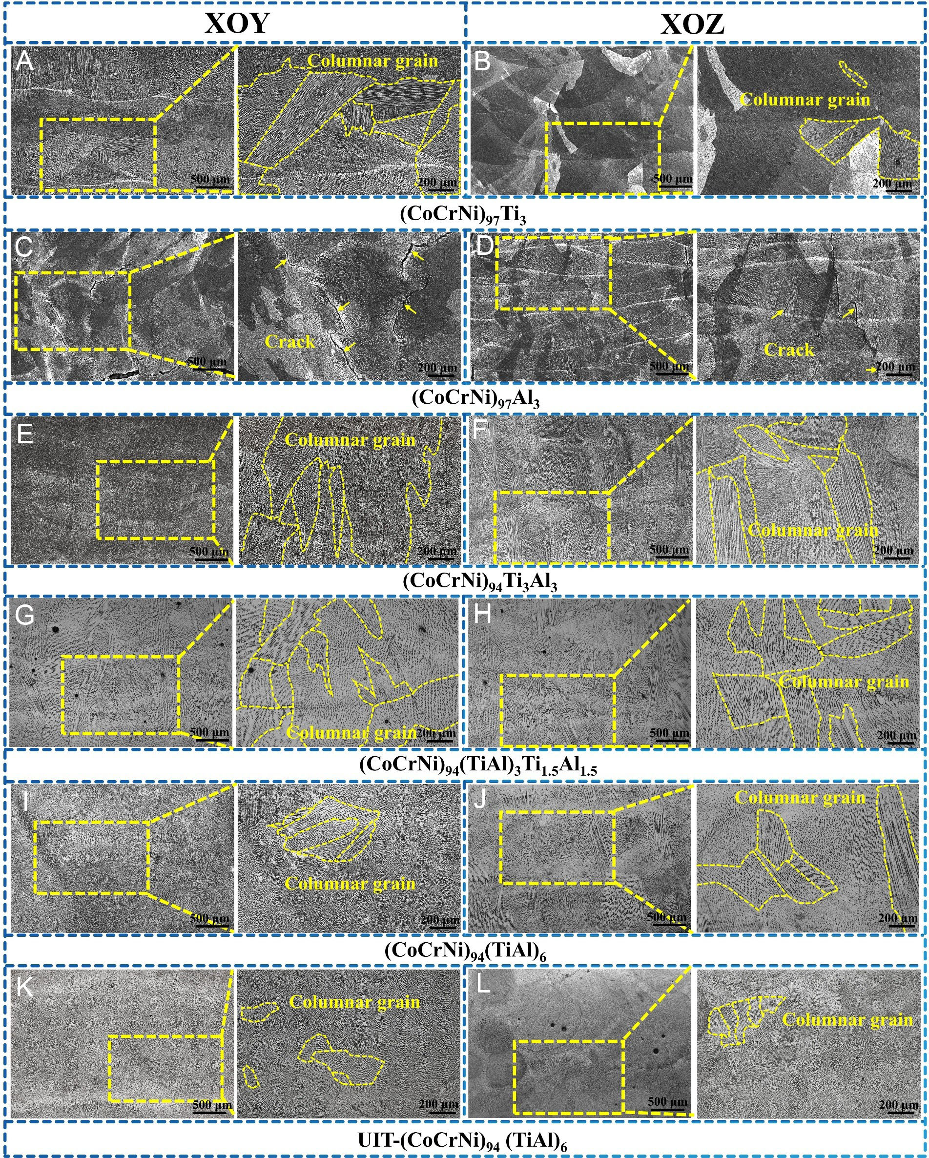
Figure 2. Microstructure of CoCrNi-based MEAs in XOY and XOZ plane. (A and B) (CoCrNi)97Ti3; (C and D) (CoCrNi)97Al3; (E and F) (CoCrNi)94Ti3Al3. (G and H) (CoCrNi)94(TiAl)3Ti1.5Al1.5; (I and J) (CoCrNi)94(TiAl)6. (K and L) UIT-(CoCrNi)94(TiAl)6. MEA: Medium-entropy alloy; UIT: ultrasonic impact treatment.
Figure 2I and J presents XOY and XOZ structures in AM (CoCrNi)94(TiAl)6 MEAs, which show differences. Only a small portion of the XOY surface contains columnar crystals, with a significant decrease in grain size and volume fraction, and no defects. The columnar crystal content on the XOZ structure slightly increases compared to the XOY surface. However, both overall size and quantity remain significantly reduced compared to (CoCrNi)94Ti3Al3 MEAs and (CoCrNi)94(TiAl)3Ti1.5Al1.5 MEAs. Figure 2K and L shows microstructures of UIT-(CoCrNi)94(TiAl)6 MEAs on XOY and XOZ surfaces. Compared with (CoCrNi)94(TiAl)6 MEAs, UIT-(CoCrNi)94(TiAl)6 MEAs exhibit a markedly reduced columnar crystal volume fraction, with only a small fraction remaining in localized areas. The columnar grains are fragmented into finer substructures, and overall grain morphology becomes more uniformly refined.
Based on metallographic analysis, SEM-energy dispersive spectroscopy (EDS) was then used for higher-magnification morphological and elemental mapping [Figure 3]. Figure 3A presents SEM and EDS results for (CoCrNi)97Ti3 MEAs. The (CoCrNi)97Ti3 MEAs exhibit a uniform cellular corrugated microstructure with well-aligned layered structures and clearly defined GBs, and no cracks or voids. EDS mapping indicates uniform distribution of all four elements throughout the matrix, with no localized elemental segregation or independent phase precipitation, confirming Ti incorporation via solid solution. Figure 3B presents results for (CoCrNi)97Al3 MEAs. Unlike the Ti-only alloy, (CoCrNi)97Al3 MEAs exhibit reticular cracks along GBs, propagating through multiple grains, accompanied by microcracks and loose voids. EDS mapping [Supplementary Figure 1] reveals Al-rich regions along GBs, suggesting a tendency of Al accumulation that reduces GB bonding strength and induces cracking.

Figure 3. SEM and EDS mapping analysis results of CoCrNi-based MEAs. (A) (CoCrNi)97Ti3; (B) (CoCrNi)97Al3; (C) (CoCrNi)94Ti3Al3; (D) (CoCrNi)94(TiAl)3 Ti1.5Al1.5; (E) (CoCrNi)94(TiAl)6; (F) UIT-(CoCrNi)94(TiAl)6. SEM: Scanning electron microscope; EDS: energy dispersive spectroscopy; MEA: medium-entropy alloy; UIT: ultrasonic impact treatment.
When Ti and Al are synergistically added, the microstructure is significantly optimized, as shown in Figure 3C. (CoCrNi)94Ti3Al3 MEAs are uniformly dense with no cracks or voids. High-magnification observation reveals a finer lamellar matrix structure compared to (CoCrNi)97Ti3 MEAs, with uniformly distributed granular nano-precipitates. EDS confirms that Ti and Al are enriched in precipitation phase regions, indicating the formation of Ti-Al-rich precipitates. Ti and Al synergistically refine the lamellar structure and promote the uniform nucleation of nano-precipitates. Figure 3D provides microstructure along with corresponding EDS results for (CoCrNi)94(TiAl)3Ti1.5Al1.5 MEAs. The alloy exhibits a highly uniform microstructure with no cracks or defects. High-magnification observation reveals a dense lamellar structure with no obvious nano-precipitates. EDS mapping shows uniform distribution of Ti and Al throughout matrix without local segregation, indicating that Ti and Al primarily exist in solid solutions.
Upon adding TiAl alloy, SEM and EDS results for (CoCrNi)94(TiAl)6 MEAs are shown in Figure 3E, revealing more pronounced microstructural optimization: low-magnification observations demonstrate further enhanced microstructural uniformity with no defects; high-magnification observation reveals a finer and more uniformly oriented lamellar structure, with the precipitation phase refined to the submicron scale and more uniformly distributed than in (CoCrNi)97Ti3 MEAs. EDS indicates enrichment of Ti and Al in precipitation phase regions, further confirming the presence of Ti-Al-rich precipitates. TiAl addition refines lamellar structure and promotes uniform precipitation of nanoscale precipitates. Figure 3F shows results for UIT-(CoCrNi)94(TiAl)6 MEAs, revealing further optimized microstructure. Low magnification exhibits exceptional uniformity with no defects; high magnification reveals denser, more uniformly dispersed nano-precipitates, and a finer lamellar structure than the AM (CoCrNi)94(TiAl)6 MEAs.
Figure 4 shows tensile data of AM CoCrNi-based MEAs at 298 and 77 K, demonstrating that the addition of Ti and Al significantly enhances the YS and ultimate tensile strength (UTS). Before discussing the mechanical properties, it is important to clarify the spatial extent of the UIT effect. The UIT treatment was applied to the entire gauge section of the tensile samples. For CrCoNi-based MEAs processed under similar conditions, the UIT-affected depth is approximately 600 μm[40]. Given a gauge cross-section of 1 mm × 1 mm, this affected layer constitutes about 60% of the total thickness on each treated surface. Therefore, the measured tensile properties reflect the integrated response of the gradient structure rather than being dominated solely by a thin surface layer, as further supported by the EBSD and heterogeneous deformation-induced (HDI) strengthening analyses below.
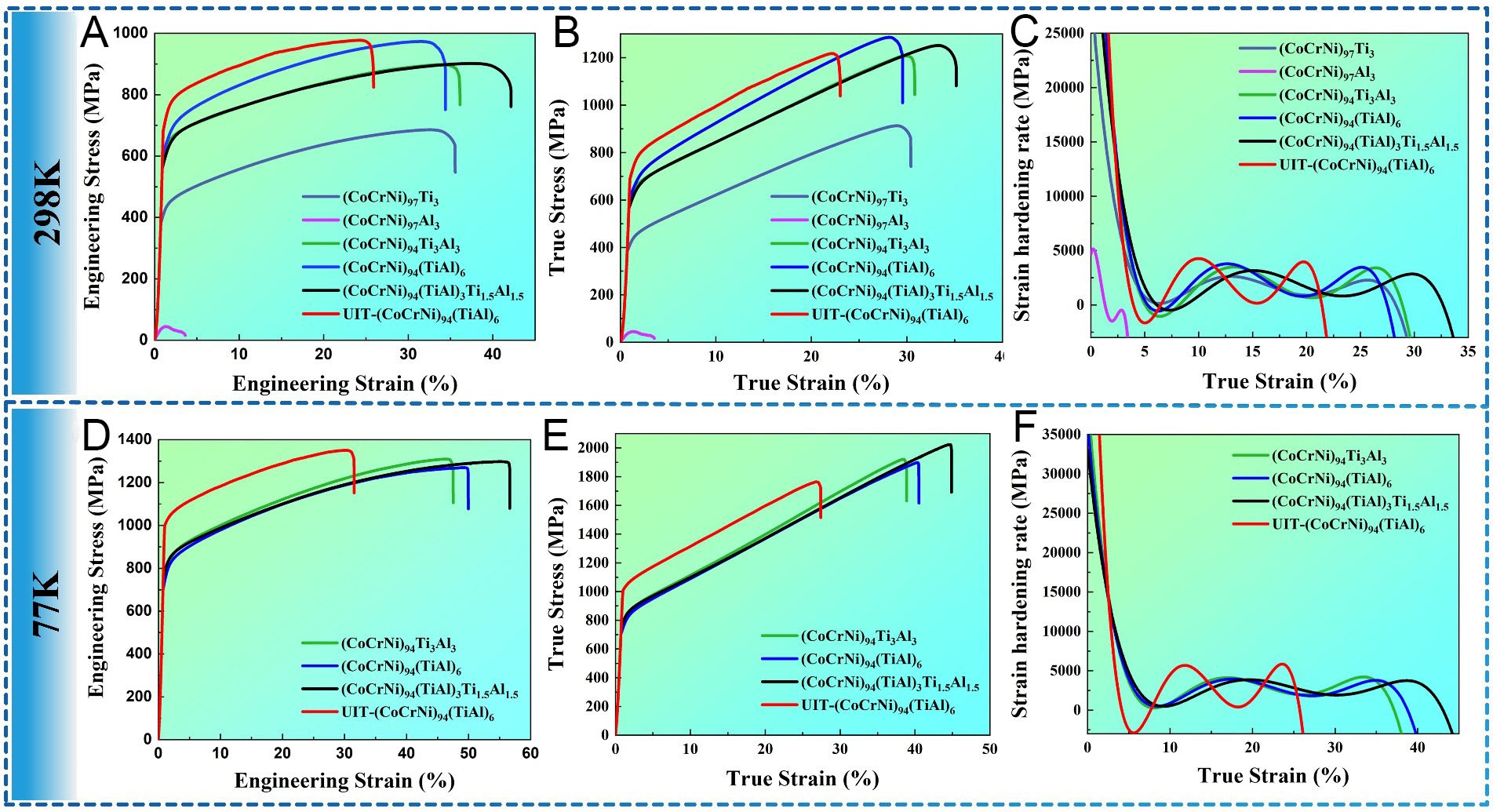
Figure 4. Mechanical properties of CoCrNi-based MEAs at 298K and 77K. (A and D) Engineering stress-engineering strain curves; (B and E) True stress-true strain curves. (C and F) Variation in strain hardening rates. MEA: Medium-entropy alloy.
For reference, CoCrNi MEAs fabricated via the identical L-DED processing route in our previous work exhibit YS of 390.6 MPa and UTS of 692.8 MPa at 298 K, YS of 626.1 MPa and UTS of 988.6 MPa at 77 K[24]. Compared with these benchmark values, the Ti-Al co-added alloys show a substantial improvement in strength, highlighting the effectiveness of the Ti-Al co-addition strategies. The (CoCrNi)97Al3 MEAs exhibit the poorest strength and ductility at 298 K, with engineering stress-strain curve rapidly declining in initial stage and fracturing at 44.7 MPa. The (CoCrNi)97Ti3 MEAs at 298 K exhibit an ultimate tensile strength (UTS) of 685.9 MPa, YS of 379.7 MPa, and an elongation at fracture of 35.5%. The co-addition of Ti and Al resulted in a substantial increase in UTS and YS. At 298 K, (CoCrNi)94Ti3Al3 MEAs exhibit a UTS of 898.5 MPa, YS of 601.5 MPa, and elongation of 36.1%. For (CoCrNi)94(TiAl)3Ti1.5Al1.5 MEAs, UTS, YS and elongation at break are 901.7 MPa, 558.4 MPa and 42.1%. The strength difference between the two is small, but plasticity of the latter is better. The (CoCrNi)94(TiAl)6 MEAs achieve a UTS of 973.5 MPa, a YS of 589.1 MPa, and an elongation of 34.4%. Tensile testing of UIT-(CoCrNi)94(TiAl)6 MEAs revealed a combination of high strength and ductility: a UTS of 977.6 MPa, a YS of 692.7 MPa, and an elongation of 25.9%. The UTS of UIT specimens is only 0.42% higher than that of AM (CoCrNi)94(TiAl)6 MEAs, but YS increases by 17.6%. However, UIT reduces the elongation of AM (CoCrNi)94(TiAl)6 MEAs by 24.7%, indicating that UIT-treated (CoCrNi)94(TiAl)6 MEAs exhibit improved room-temperature properties but reduce ductility. A comparative summary of mechanical properties against representative CoCrNi-based MEAs from the literature is presented in Supplementary Figure 2. It is well known that CoCrNi-based MEAs exhibit excellent performance at low temperatures, which is corroborated by the present tensile results. At low temperature, a UTS of 1,309.6 MPa and a YS of 705.9 MPa is obtained for (CoCrNi)94Ti3Al3 MEAs, along with an elongation of 47.5%. (CoCrNi)94(TiAl)3Ti1.5Al1.5 MEAs exhibit a UTS of 1,297.9 MPa, a YS of 742.8 MPa and an elongation of 56.6%. The strength difference between the two is small, but plasticity of the latter is better. The mechanical properties of (CoCrNi)94(TiAl)6 MEAs, UTS of 1,269.4 MPa, YS of 709.5 MPa and elongation of 49.9% , indicate a favorable strength-ductility synergy. With a UTS of 1350.1 MPa, a YS of 997.7 MPa, and an elongation of 31.5%, UIT-(CoCrNi)94(TiAl)6 MEAs demonstrate excellent tensile properties. The strength of UIT-(CoCrNi)94(TiAl)6 MEAs is 6.4% and 40.6% higher than that of AM (CoCrNi)94(TiAl)6 MEAs.
It is worth noting that the UIT-induced strengthening comes at the expense of ductility. At 298 K, the elongation decreases from 34.4% to 25.9%; at 77 K, it decreases from 49.9% to 31.5%. This strength-ductility trade-off is a common phenomenon in metallic materials processed by severe plastic deformation techniques. The increased dislocation density, refined grain structure, and high-density stacking faults introduced by UIT effectively impede dislocation motion, thereby elevating the yield strength. However, these same microstructural features also reduce the dislocation mean free path and limit the capacity for further strain hardening, resulting in reduced elongation.
Figure 4C and F display strain hardening curves of AM CoCrNi-based MEAs. The strain hardening rate can be broadly categorized into three stages: elastoplastic transition, hardening stage, and failure stage. During the first stage, strain hardening rate drops sharply across all samples as deformation transitions from elastic to plastic. In the second stage, the strain hardening rate curve exhibits distinct transient characteristics. Secondary strain hardening imparted a high hardening capability to the alloy. In the third stage, when the true stress value exceeded UTS, strain hardening rate decreased again until fracture.
To further investigate microstructural differences between (CoCrNi)94(TiAl)6 MEAs on XOY and XOZ planes under UIT, EBSD analysis was performed, with results shown in Figures 5 and 6. Figure 5A-J depict the inverse polar figures (IPF), polar figures (PF), recrystallization distribution patterns, recrystallization distribution statistics, GB distribution patterns, and grain statistics for (CoCrNi)94(TiAl)6 MEAs and UIT-(CoCrNi)94(TiAl)6 MEAs on XOY plane. A comparative analysis of (CoCrNi)94(TiAl)6 MEAs and UIT-(CoCrNi)94(TiAl)6 MEAs samples reveals the following: The IPF results reveal relatively random color distribution across grains, with no distinct orientation observed. The PF in the figure indicates that texture strengths of (CoCrNi)94(TiAl)6 MEAs and UIT-(CoCrNi)94(TiAl)6 MEAs are 11.56 and 5.99, respectively. These results clearly demonstrate that the texture of UIT-(CoCrNi)94(TiAl)6 MEAs is lower than that of (CoCrNi)94(TiAl)6 MEAs.

Figure 5. EBSD analysis for AM (CoCrNi)94(TiAl)6 and UIT-(CoCrNi)94(TiAl)6 in XOY plane. (A and F) IPF; (B and G) PF; (C and H) Recrystallization microstructure distribution; (D and I) Grain boundary distribution, grain size distribution; (E and J) KAM, local misorientataion statistics. EBSD: Electron backscatter diffraction; AM: additive manufacturing; UIT: ultrasonic impact treatment; IPF: inverse polar figures PF: polar figures; KAM: Kernel Average Misorientation.

Figure 6. EBSD analysis for (CoCrNi)94(TiAl)6 and UIT-(CoCrNi)94(TiAl)6 in XOZ plane. (A and F) IPF; (B and G) PF; (C and H) Recrystallization microstructure distribution; (D and I) Grain boundary distribution, grain size distribution; (E and J) KAM, local misorientataion statistics. AM: Additive manufacturing; UIT: ultrasonic impact treatment; EBSD: electron backscatter diffraction; XOZ: IPF: inverse polar figures PF: polar figures; KAM: Kernel Average Misorientation.
Figure 5C and H show distribution of recrystallization, recovery, and deformation microstructures in XOY plane of (CoCrNi)94(TiAl)6 MEAs and UIT-(CoCrNi)94(TiAl)6 MEAs. EBSD phase maps [Supplementary Figure 3] further confirm that both the as-deposited and UIT-treated matrices consist almost entirely of a single FCC phase, with no macroscopic secondary phases detected at the EBSD resolution limit. In (CoCrNi)94(TiAl)6 MEAs sample, recrystallized, recovered, and deformed regions were observed, occupying 4.4%, 39.7%, and 55.9% of volume, respectively. In UIT-(CoCrNi)94(TiAl)6 MEAs sample, fractions of recrystallized, recovered, and deformed regions were 1.5%, 6.2%, and 92.3%, respectively. (CoCrNi)94(TiAl)6 MEAs consisted primarily of recovered and deformed regions, whereas UIT-(CoCrNi)94(TiAl)6 MEAs are predominantly characterized by deformed regions. This dramatic increase in deformed fraction and decrease in recrystallized fraction indicate that UIT-induced severe plastic deformation introduces a high density of dislocations and deformation substructures that persist in the final microstructure. The grain refinement observed after UIT is primarily achieved through deformation-induced fragmentation of the original columnar grains via dislocation slip, dislocation cell formation, and subgrain development, rather than through complete dynamic recrystallization. The refined grains retain significant internal strain, as evidenced by the elevated Kernel Average Misorientation (KAM) values discussed.
Figure 5D and I show the GB distribution maps for (CoCrNi)94(TiAl)6 MEAs and UIT-(CoCrNi)94(TiAl)6 MEAs. In these maps, low-angle grain boundaries (LAGBs) are depicted in red, primarily consisting of boundaries with misorientations between 2° and 5°. High-angle grain boundaries (HAGBs), shown in blue, correspond to misorientations exceeding 15°. Boundaries with misorientations between these ranges are classified as medium-angle grain boundaries (MAGBs) and are shown in green. In (CoCrNi)94(TiAl)6 MEAs, fractions of LAGBs, MAGBs, and HAGBs are 38.9%, 16.3%, and 44.8%, respectively. Following UIT, these fractions shift to 41.0%, 20.1%, and 38.9%, indicating an increase in GBs between 2-15° after UIT. Quantitative analysis shows that UIT reduces the average grain size from 97.99 μm to 71.04 μm on the XOY plane. Figure 5E and J show KAM images of (CoCrNi)94(TiAl)6 MEAs and UIT-(CoCrNi)94(TiAl)6 MEAs, respectively, reflecting the density and strain energy of geometrically necessary dislocations (GNDs) in local regions. The average KAM value increases from 0.89° to 1.17° after UIT. EBSD data indicate increased local orientation difference after UIT, suggesting higher GNDs densities, which implies greater stress concentration and higher strain.
Figure 6A-J illustrates the EBSD characterization results for (CoCrNi)94(TiAl)6 MEAs and UIT-(CoCrNi)94(TiAl)6 MEAs specimens on XOZ section. These include IPF maps, PF maps, recrystallization fraction maps and statistical analyses, GB maps, grain size distribution histograms, KAM maps, and local misorientation profiles. Upon comparing (CoCrNi)94(TiAl)6 MEAs and UIT-(CoCrNi)94(TiAl)6 MEAs samples, similar trends to those on XOY plane emerge. The IPF maps demonstrate relatively random coloration across different grains, suggesting no discernible crystallographic texture. PF analysis indicates texture intensities of 11.65 and 7.83 for (CoCrNi)94(TiAl)6 MEAs and UIT-(CoCrNi)94(TiAl)6 MEAs samples on XOZ plane, respectively. While the reduction in texture intensity is smaller compared to that on XOY plane, UIT-processed alloy maintains a lower texture intensity. The microstructural constituents on XOZ plane - namely recrystallized, recovered, and deformed regions - are depicted in Figure 6C and H. (CoCrNi)94(TiAl)6 MEAs contain 4.1% recrystallized, 39.9% recovered, and 56.0% deformed fractions. In contrast, UIT-treated counterpart comprises 1.8% recrystallized, 9.0% recovered, and 89.2% deformed regions. This distribution pattern on XOZ plane closely resembles that observed on XOY plane, further confirming that the grain refinement induced by UIT arises from deformation-induced fragmentation rather than recrystallization. The persistent high deformed fraction after UIT reflects the final highly strained state of the material. GB characteristics are shown in Figure 6D and I. The proportions of LAGBs, MAGBs, and HAGBs in (CoCrNi)94(TiAl)6 MEAs are 25.7%, 30.2%, and 44.1%, respectively. After UIT application, these values become to 40.2%, 18.5%, and 41.3%, reflecting a modest increase in boundaries with misorientations ranging from 2° to 15°. Quantitatively, UIT reduces the average grain size from 147.23 μm to 54.67 μm on the XOZ plane. The KAM maps in Figure 6E and J provide insight into the local strain distribution. The average KAM value increased from 0.8° to 1.02° after UIT, indicating UIT-treated sample exhibits enhanced stress concentration relative to its untreated counterpart.
To investigate the nano-precipitation strengthening mechanism, transmission electron microscopy (TEM) characterization was performed on AM (CoCrNi)94(TiAl)6 MEAs. The resulting bright-field and high-angle annular dark-field (HAADF) micrographs are compiled in Figure 7. The bright-field images reveal a homogeneous distribution of near-spherical precipitates, roughly 200 nm in size, embedded within the matrix. SEM mainly reveals the precipitate morphology and distribution, whereas TEM provides the accurate size measurement. These precipitates are associated with pronounced dislocation tangles and lattice distortion in their immediate surroundings. EDS analysis [Figure 7C-F] detects Ti, Al, and O enrichment in the spherical precipitates. Both spherical and polyhedral precipitates exhibit a core-shell structure, characterized by Ti-rich shells surrounding Al/O-rich cores. The spherical nanoparticles are identified as Ti-Al-O complex oxides formed during L-DED processing. Selected area electron diffraction (SAED) analysis [Figure 7D], combined with STEM-EDS elemental mapping, identifies the spherical precipitates as TiAl2O5 based on SAED indexing and EDS analysis. The corresponding crystal structure schematically represented in Figure 7E. HAADF-STEM EDS mapping [Figure 7C-F] reveals distinct Ti enrichment at the periphery and Al/O enrichment in the center across multiple particles, providing strong chemical evidence for the core-shell heterostructure, further supported by SAED crystallographic analysis [Figure 7D]. While high-resolution transmission electron microscope (HRTEM) atomic-scale imaging would be valuable for direct interface visualization, the combined chemical and crystallographic evidence robustly supports the core-shell identification. Literature reports indicate that the polyhedral core-shell structures consist of alumina coated with titanium dioxide, following formation mechanisms distinctly different from those governing spherical precipitate evolution. In contrast, the formation of the spherical core-shell architecture in the present work is attributed to the L-DED environment: Al has a stronger affinity for O than Ti, so Al-O-rich cores nucleate first during rapid solidification, followed by Ti enrichment around them; the high cooling rate freezes this segregated structure before interdiffusion can homogenize it, while the pre-alloyed TiAl master alloy ensures local co-location of Ti and Al to facilitate this sequential precipitation. The SAED patterns in Figure 7D also reveal matrix reflections corresponding to the characteristic FCC structure of the CoCrNi solid solution, with no additional spots indicative of secondary or ordered phases. This is further supported by HRTEM lattice fringe measurements [Figure 7I] and EDS mapping [Figure 3], which confirm that the matrix retains a uniform Co-Cr-Ni composition while Ti and Al are primarily concentrated in the precipitate regions. These observations confirm that the matrix remains an FCC solid solution after Ti and Al addition.

Figure 7. TEM analysis of (CoCrNi)94(TiAl)6 MEAs. (A) Bright field; (B) HAADF. (C and F) elements mapping results of Co, Cr, Ni, Ti, Al and O; (D) SAED of nanoprecipitates; (E) Crystal Structural Model; (G and H) Bright field; (I) IFFT. FCC: TEM: transmission electron microscope; MEA: medium-entropy alloy; HAADF: high-angle annular dark-field; SAED: selected area electron diffraction; IFFT: inverse fast Fourier transform.
Regarding the role of Ti-Al-O particles, they function predominantly as beneficial strengthening phases rather than deleterious inclusions. They are nanoscale with spherical morphology and uniform dispersion, and TEM reveals pronounced dislocation tangles around them with no interfacial debonding. No oxide-induced crack initiation was observed in tensile tests, and the high elongations confirm their benign nature. In contrast, Al-only addition produced coarse GB oxides that severely degraded properties. The strengthening contribution of these core-shell precipitates arises from three aspects: Orowan bypassing (dislocations loop around the hard oxide particles), reduced stress concentration (the Ti-rich shell buffers modulus mismatch between the core and matrix), and enhanced HDI strengthening (dislocation pile-ups at particles sustain long-range back stress). These effects are directly reflected in the macroscopic mechanical properties. In the (CoCrNi)94(TiAl)6 MEAs sample [Figure 7G-I], high-density dislocation networks surround the nanoprecipitates. Extreme thermal gradients and cyclic thermal stresses caused these dislocations to cluster at grain boundaries and form dislocation walls within grains.
Figure 8 shows bright-field and HAADF micrographs of UIT-(CoCrNi)94(TiAl)6 MEAs. Bright-field imaging indicates that precipitate size undergoes refinement from roughly 200 nm in as-fabricated state to approximately 100 nm post-UIT, accompanied by enhanced distribution uniformity and stronger matrix interface bonding. EDS analysis [Figure 8C and F] confirms more homogeneous Ti and Al partitioning within precipitates. The spherical precipitates also exhibit the same core-shell structure, with Ti-rich shells and Al/O-rich cores, consistent with the as-deposited state. SAED analysis [Figure 8G], combined with STEM-EDS mapping, identifies these spherical precipitates as Ti7Al2O15 based on SAED indexing. The corresponding crystal structure schematically represented. We acknowledge that atomic-resolution HRTEM would be valuable for further confirmation. The phase transformation from TiAl2O5 to Ti7Al2O15 during UIT is attributed to severe plastic deformation. The high-frequency impacts introduce massive mechanical energy, increasing internal free energy through dislocations and lattice strain, which drives a mechanochemical transformation. Concurrently, high-density defects provide short-circuit diffusion paths, and localized adiabatic heating at interfaces accelerates atomic mobility, making the rapid stoichiometric shift kinetically viable. A noteworthy observation in UIT-(CoCrNi)94(TiAl)6 MEAs sample [Figure 8H] is the presence of high-density dislocation lines and stacking faults surrounding nanoprecipitates, representing a substantial increase in dislocation density compared to (CoCrNi)94(TiAl)6 MEAs. These stacking faults were characterized in the as-UIT-treated state rather than in post-deformation tensile specimens, indicating they are introduced by UIT rather than tensile deformation. The UIT-induced refinement of these oxides further enhances their strengthening efficacy while reducing stress concentration risks. High-resolution imaging quantitatively confirms a stacking fault width of approximately 10.42 nm, with pronounced dislocation pile-up and slip characteristics at faulted regions. These microstructural observations demonstrate that UIT achieves concurrent precipitate refinement through severe plastic deformation and introduces high-density dislocations alongside stacking faults via severe strain, thereby markedly improving both microstructural uniformity and strengthening effectiveness of the alloy.
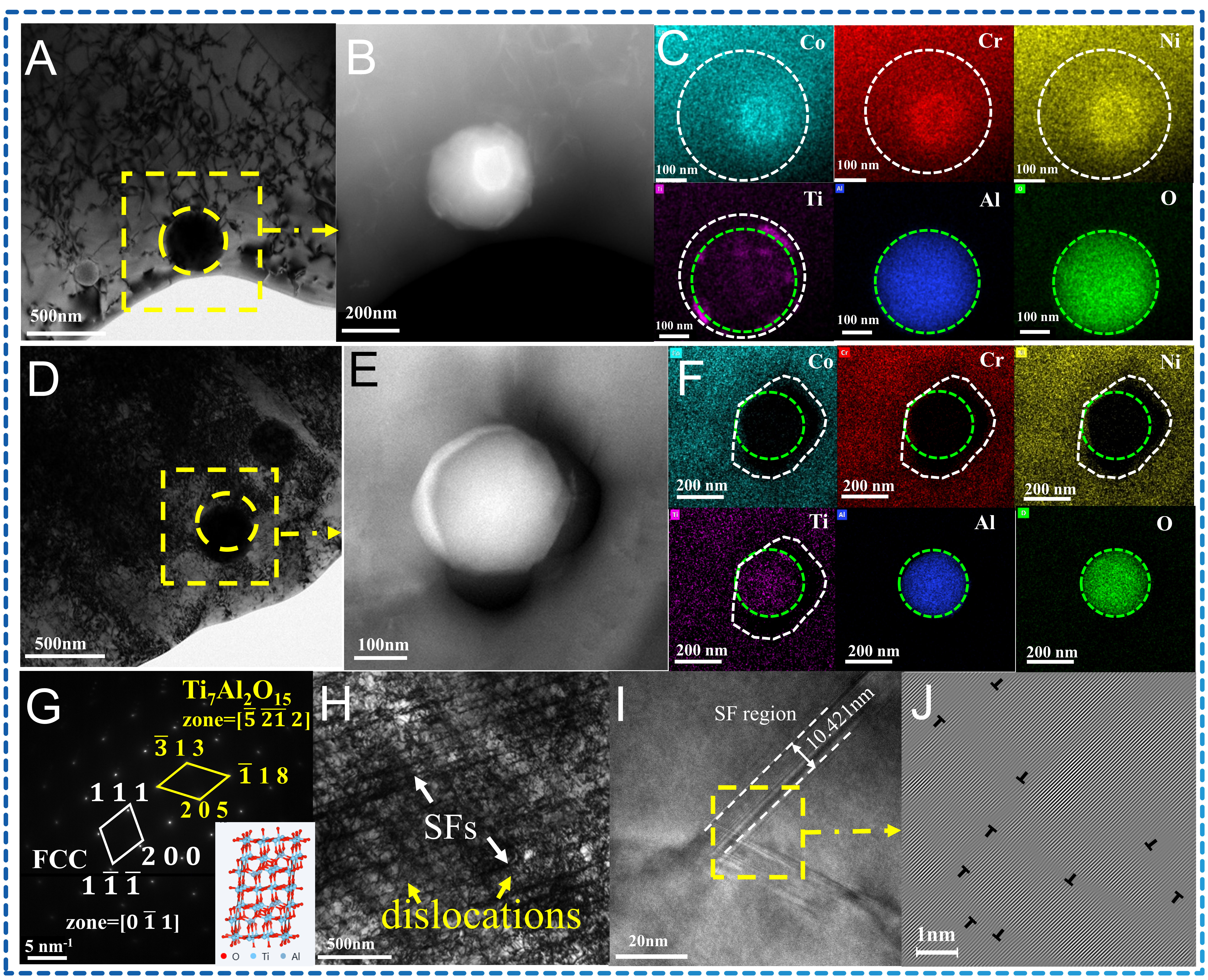
Figure 8. TEM analysis of UIT-(CoCrNi)94(TiAl)6 MEAs. (A and D) Bright field; (B and E) HAADF; (C and F) elements mapping results of Co, Cr, Ni, Ti, Al and O; (G) SAED of nanoprecipitates and crystal structural model; (H and I) Bright field; (J) IFFT. FCC: SF: stacking fault; TEM: transmission electron microscope; UIT: ultrasonic impact treatment; MEA: medium-entropy alloy; HAADF: high-angle annular dark-field; SAED: selected area electron diffraction; IFFT: inverse fast Fourier transform.
A comparison of microstructural features of AM and UIT states clearly reveals the regulatory role of the UIT process in the strengthening mechanism of (CoCrNi)94(TiAl)6 MEAs. AM-treated alloy primarily relies on the synergistic effect of dispersion strengthening from nano-precipitates and moderately dense dislocations. In contrast, UIT-treated state establishes a more efficient strengthening system through multiple mechanisms: precipitation refinement, dislocation proliferation, and stacking fault formation. Specifically, UIT treatment reduces size and enhances the uniformity of the precipitated phase, thereby increasing its resistance to dislocation motion. Concurrently, the introduction of high-density dislocations and stacking faults further increases dislocation motion resistance, significantly improving the alloy’s work-hardening capacity. This microstructural evolution directly correlates with enhanced mechanical properties. Subsequent analysis reveals that stacking fault introduction plays a role in moderating the ductility loss of the UIT-treated alloy. Although the emergence and expansion of stacking faults create supplementary slip channels for dislocation movement and mitigate localized stress concentrations, they cannot fully compensate for the ductility reduction caused by the increased dislocation density, grain refinement, and refined precipitates. Consequently, the UIT-treated alloy exhibits a substantial increase in yield strength accompanied by a decrease in elongation, reflecting a classical strength-ductility trade-off.
Subsequent analysis reveals that stacking fault introduction plays an important role in moderating the ductility loss of the UIT-treated alloy. The emergence and expansion of stacking faults create supplementary slip channels for dislocation movement, mitigating localized stress concentrations and helping to retain ductility to some extent under the heavily deformed state. Nevertheless, the overall mechanical response remains a strength-ductility trade-off, as the UIT-induced high-density dislocations and grain refinement lead to a substantial increase in yield strength at the expense of elongation.
MD simulations were used to investigate the microstructural evolution mechanism in (CoCrNi)94(TiAl)6 MEAs under UIT, revealing the atomic-scale origins of UIT-induced property enhancement via dislocation and stacking fault behavior. The simulation employed a uniform FCC solid solution as initial atomic configuration [Figure 9A], with entire system comprising 128,000 atoms. A periodic sinusoidal impact stress with an amplitude of approximately ±20,000 MPa and a period of approximately 1 ps was applied to simulate the ultrasonic impact loading [Figure 9B], while the evolution of dislocation density is shown in Figure 9C. Each atom experienced a maximum force of 5 eV/Å, with a total force of 15,000 eV/Å. The simulation proceeded with a timestep of 0.001 ps for 5,000 iterations, corresponding to a total duration of 5 ps. The time points (d)-(k) marked on load curve correspond to subsequent microstructural evolution stages. It should be noted that the 5 ps simulation duration is much shorter than the experimental UIT process (120 s) due to computational constraints. Therefore, the MD results represent an idealized short-pulse response illustrating the qualitative mechanisms of defect initiation, rather than a direct replication of the full UIT process. Results indicate that under initial uniform solid solution atomic configuration, periodic sinusoidal ultrasonic shock load first induces total dislocation nucleation at GBs and lattice defects [Figure 9D-G]. During initial impact phase, full dislocations predominantly adopt 1/6<112> (Shockley) configuration, rapidly nucleating and growing as the load increases. Concurrently, dislocation density and stacking fault area increase, with dislocation lines undergoing slip, intersection, and entanglement to progressively form a complex dislocation network. As shock load cyclically rises and falls, full dislocations further decompose into 1/6<110> Stair-rod and 1/3<100> Hirth dislocations, accompanied by formation and expansion of stacking fault layers (as illustrated in Figure 9H-K). At load peak phase, dislocation density reaches its maximum value, with proportions of 1/6<110> Stair-rod and 1/3<100> Hirth dislocations significantly increasing. Stacking faults interconnect to form regular stacking fault zones. During the final impact stage, dislocation network stabilizes. Some dislocations undergo dynamic recovery and rearrangement, while dislocation bands contract and transform into uniformly distributed dislocation regions, ultimately forming a mixed dislocation structure dominated by partial dislocations.
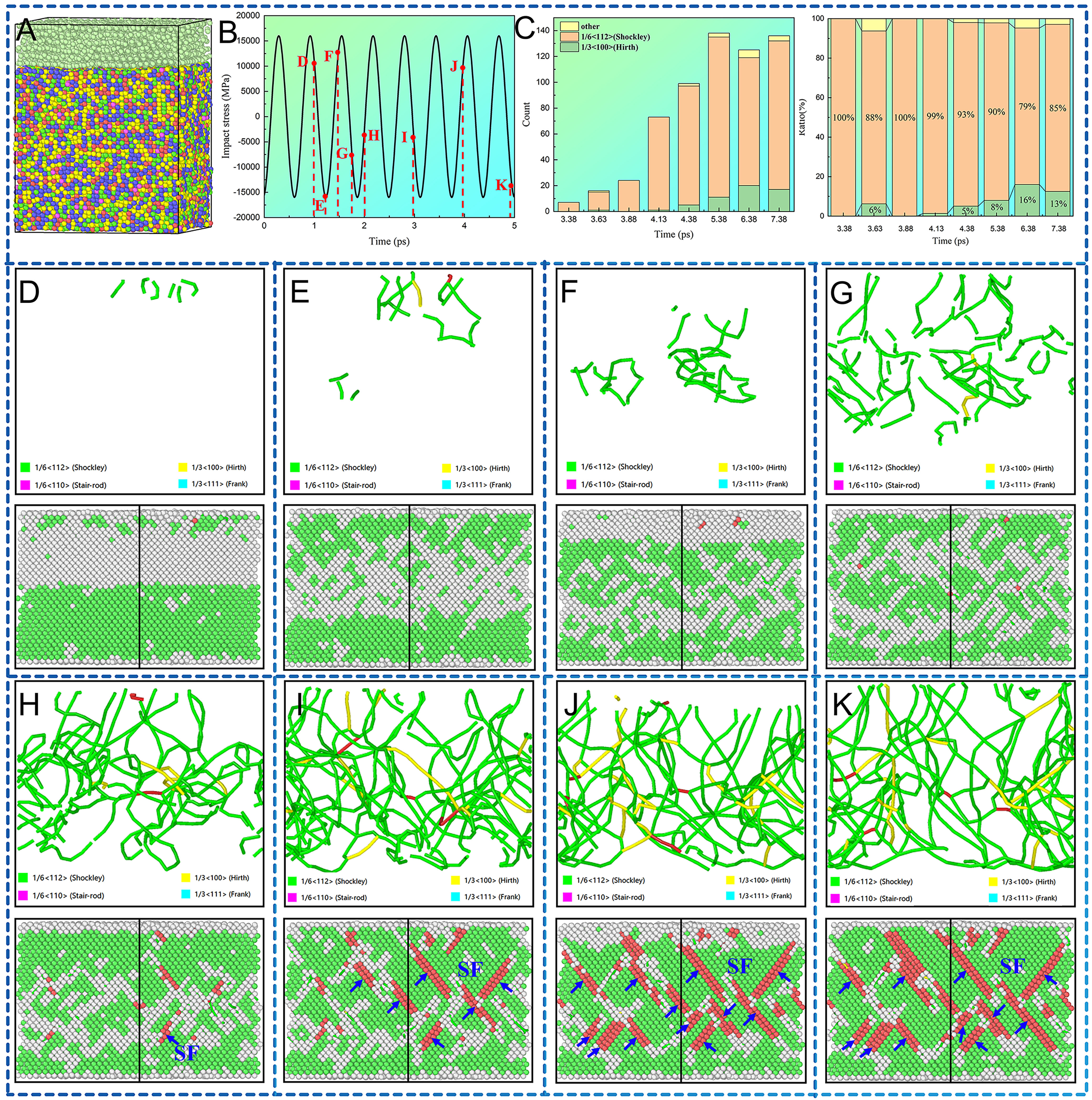
Figure 9. MD results of UIT-(CoCrNi)94(TiAl)6 MEAs. (A) crystal structure model. (B) ultrasonic impact-stress waveform. The black curve represents the applied impact stress as a function of time, the red circles indicate the impact-stress values at the specific time points corresponding to Figure 9D-K, and the red dashed lines mark the exact time positions of these frames; (C) number and proportion of dislocations; (D-K) evolution of dislocations and stacking faults. MD: Molecular dynamics; UIT: ultrasonic impact treatment; MEA: medium-entropy alloy.
These simulation findings demonstrate exceptional concordance with experimentally observed mechanical property enhancements, revealing UIT strengthening mechanism at atomic resolution. This provides fundamental theoretical guidance and technical foundations for designing high-entropy alloys with superior strength-ductility combinations, while establishing essential microstructural evolution principles for developing advanced alloy strengthening methodologies.
Both UIT-treated and as-deposited states of the alloy display exceptional combinations of strength and ductility. The observed enhancement results from the integration of established strengthening mechanisms, including solid-solution strengthening, grain refinement strengthening, precipitation strengthening, and strain hardening. During deformation, persistent accumulation of GNDs occurs due to microstructural and mechanical property inhomogeneities[41-43]. This heterogeneity distribution of GNDs under asynchronous deformation introduces a unique mechanism designated as HDI strengthening[44,45]. For quantitative assessment of HDI contribution to layered heterostructure alloy strength, HDI stress was determined via LUR tensile testing, with results presented in Figure 10A. The cyclic loading true stress-true strain curves reveal that stress plateau and peak stress of UIT-(CoCrNi)94(TiAl)6 MEAs at 77 K and 298 K are significantly higher than those of AM (CoCrNi)94(TiAl)6 MEAs. Moreover, the alloy exhibits a markedly superior strain hardening rate at 77K. This phenomenon stems from increased dislocation motion resistance and reduced stacking fault energy at low temperatures, promoting decomposition of full dislocations into Shockley partial dislocations and formation of stacking faults. This enhances the short-range hindrance effect of dislocation motion, enabling the alloy to exhibit more pronounced cyclic hardening capability in cryogenic environments.
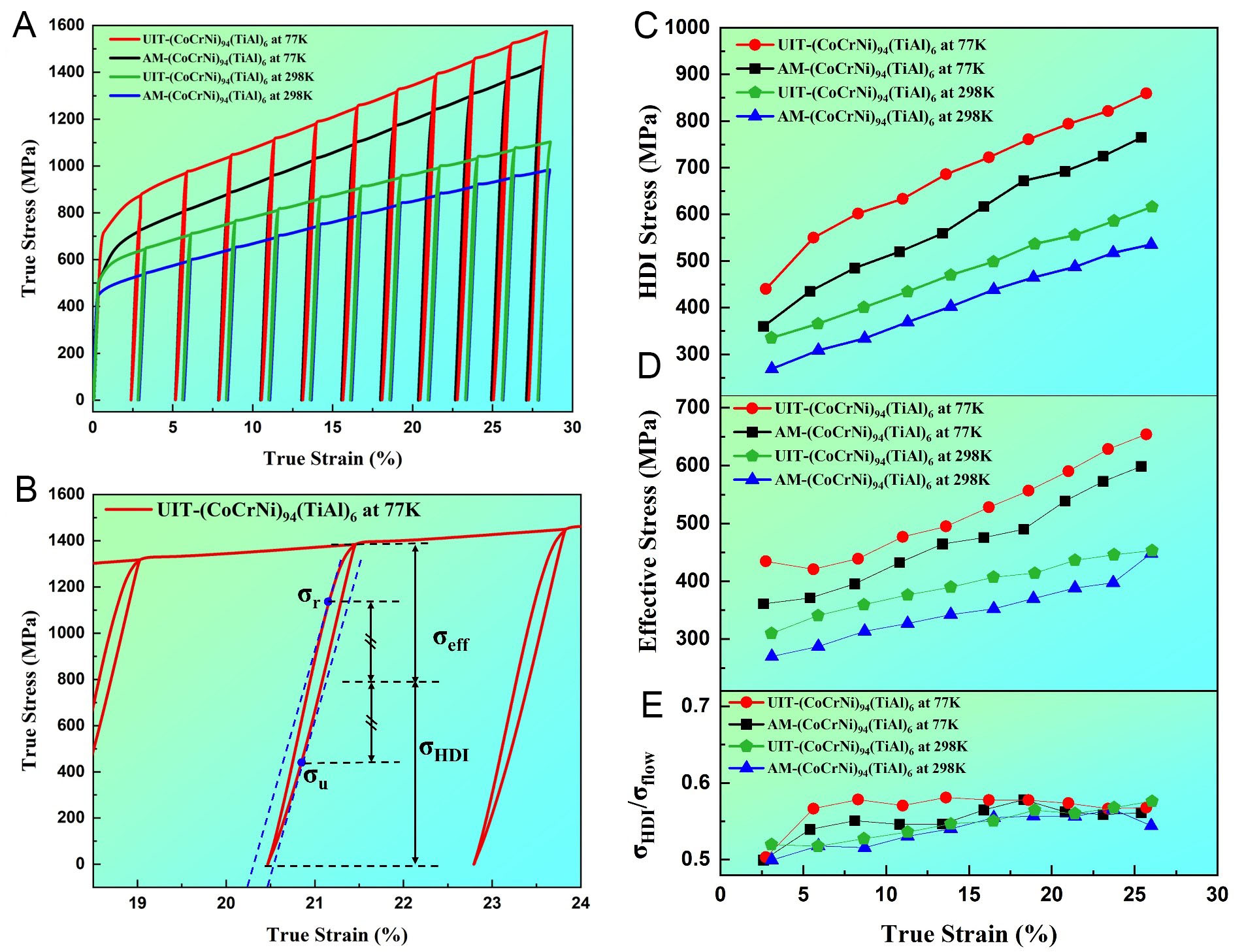
Figure 10. HDI strengthening effect of AM and UIT (CoCrNi)94(TiAl)6 MEAs. (A) LUR curve; (B) LUR test principle; (C) HDI enhancement; (D) effective stress; (E) σHDI/σflow. AM: Additive manufacturing; UIT: ultrasonic impact treatment; HDI: heterogeneous deformation-induced; MEA: medium-entropy alloy; LUR: load-unload-reload.
Through LUR experiments, the LUR procedure is illustrated in Figure 10B, and HDI stress is derived from the following expression[46,47]:
where σHDI represents HDI stress, σu and σr are yield strengths during unloading and reloading, respectively. Notably, Figure 10C indicates that HDI strengthening generally increases with deformation; UIT-(CoCrNi)94(TiAl)6 MEAs exhibit superior strengthening at 77K. The flow stress may be decomposed into two components - effective stress and HDI stress - and HDI contribution to flow stress can be evaluated via specified formula:
The distributions σf and σeff represent flow stress and effective stress, respectively.
Figure 10C and D demonstrates that effective stress σeff exhibits minimal variation with increasing deformation, remaining within 200 MPa. In contrast, the magnitude of HDI stress is significant, ranging from 200 MPa to 400 MPa. Consequently, strength enhancement is primarily attributed to HDI strengthening. Calculating HDI’s contribution to flow stress yields results shown in Figure 10E. It is evident that HDI strengthening accounts for over 50% of the total flow stress, and its contribution continuously increases with deformation. For UIT-(CoCrNi)94(TiAl)6 MEAs, HDI-induced stress contribution reaches up to 60% of total flow stress at both 77 K and 298 K. This confirms that HDI strengthening is the core mechanism driving strength enhancement of UIT-(CoCrNi)94(TiAl)6 MEAs during cyclic loading. This result aligns closely with microstructural characterization. The high-density dislocations and nano-precipitates introduced by UIT continuously interact with dislocations during cyclic deformation, forming stable long-range stress fields that drive sustained HDI stress growth.
CONCLUSIONS
This study systematically investigates effects of different Ti and Al addition methods and UIT on microstructure and mechanical properties of AM CoCrNi-based MEAs. The main conclusions are as follows. The methods of Ti and Al addition have a determining influence on both microstructural evolution and mechanical behavior of the alloy. When Al is added alone, the element tends to segregate significantly at GBs, inducing numerous intergranular cracks that severely disrupt microstructural continuity and degrade alloy’s service reliability. While Ti can be dissolved into solid solution when added alone, its strengthening effect is limited. In contrast, synergistic addition of Ti and Al - particularly in the form of TiAl master alloy - effectively promotes uniform dispersion of nanoscale Ti-Al-O composite precipitates while simultaneously refining lamellar substructure. This approach, by leveraging combined effects of precipitation-induced and grain refinement strengthening, significantly enhances both strength and ductility of the alloy without inducing crack formation. UIT further significantly optimized (CoCrNi)94(TiAl)6 MEAs significantly: it induced severe plastic deformation that fragmented the columnar grains into finer substructures through intensive dislocation activity and subgrain formation, accompanied by a substantial increase in dislocation density and the introduction of high-density stacking faults. Additionally, UIT further refined nano-precipitated phases, improved their distribution uniformity, and optimized their crystal structure. These microstructural evolutions collectively underpin a substantial elevation in YS, particularly at 77 K. The YS of UIT-treated alloy exhibits a 40.6% increase compared to the as-AM state, demonstrating a prominent advantage in low-temperature mechanical properties. However, this strengthening is accompanied by a reduction in elongation, from 34.4% to 25.9% at 298 K and from 49.9% to 31.5% at 77 K, reflecting a classic strength-ductility trade-off. Nevertheless, the UIT-treated alloy’s exceptional strength at cryogenic temperatures highlights its potential for load-bearing applications in extreme environments where high strength is the primary requirement. Despite this trade-off, the combination of alloying and UIT constitutes an effective synergistic strengthening approach from a processing perspective. Alloying introduces uniform nano-precipitates, establishing a foundation for strengthening; UIT constructs a more robust dislocation movement barrier system by introducing high-density dislocations, stacking faults, and further microstructural refinement. MD simulations reveal dynamic processes of dislocation nucleation, slip, and stacking fault formation during UIT at atomic scale. Analysis of mechanical properties and stress field evolution indicates that HDI strengthening is the core mechanism driving strength enhancement of the alloy, particularly after UIT, contributing over 50% to the flow stress. The essence of HDI strengthening stems from the synergistic interaction between a long-range stress field generated by high-density dislocations, nano-precipitates, and layer formation, together with short-range hindrance effects. This synergistic action continuously hinders dislocation motion, thereby conferring significantly enhanced deformation resistance upon the alloy.
DECLARATIONS
Authors’ contributions
Conceptualization: Zhao, S.; Bi, X.; Yuan, Z.
Data curation: Zhao, S.; Yuan, Z.
Formal analysis: Zhao, S.
Investigation: Zhao, S.
Validation: Zhao, S.; Lu, K.; Yuan, Z.
Visualization: Zhao, S.
Writing-original draft: Zhao, S.
Methodology: Bi, X.; Yuan, Z.; Li, T.
Supervision: Bi, X.; Lu, K.; Li, T. Li, R.
Writing - review & editing: Bi, X.; Li, T.
Project administration: Lu, K.; Li, R.
Resources: Lu, K.; Li, R.
Software: Li, T.
Funding acquisition: Bi, X.; Li, R.
Availability of data and materials
The data that support the findings of this study are available from the corresponding author upon reasonable request.
AI and AI-assisted tools statement
Not applicable.
Financial support and sponsorship
This work was supported by the National Natural Science Foundation of China (No. 52475359 & No. 52505382).
Conflicts of interest
All authors declared that there are no conflicts of interest.
Ethical approval and consent to participate
Not applicable.
Consent for publication
Not applicable.
Copyright
© The Author(s) 2026.
Supplementary Materials
REFERENCES
1. An, N.; Sun, Y.; Gao, L.; et al. Long-term structural stability and excellent mechanical properties of CoCrNi system medium entropy alloys. J. Alloy. Compd. 2022, 914, 165206.
2. Gludovatz, B.; Hohenwarter, A.; Catoor, D.; Chang, E. H.; George, E. P.; Ritchie, R. O. A fracture-resistant high-entropy alloy for cryogenic applications. Science 2014, 345, 1153-8.
3. Yeh, J.; Chen, S.; Lin, S.; et al. Nanostructured high-entropy alloys with multiple principal elements: novel alloy design concepts and outcomes. Adv. Eng. Mater. 2004, 6, 299-303.
4. Miao, J.; Slone, C.; Smith, T.; et al. The evolution of the deformation substructure in a Ni-Co-Cr equiatomic solid solution alloy. Acta. Materialia. 2017, 132, 35-48.
5. Wu, Z.; Bei, H.; Pharr, G.; George, E. Temperature dependence of the mechanical properties of equiatomic solid solution alloys with face-centered cubic crystal structures. Acta. Materialia. 2014, 81, 428-41.
6. Wu, Z.; Bei, H.; Otto, F.; Pharr, G.; George, E. Recovery, recrystallization, grain growth and phase stability of a family of FCC-structured multi-component equiatomic solid solution alloys. Intermetallics 2014, 46, 131-40.
7. Gludovatz, B.; Hohenwarter, A.; Thurston, K. V.; et al. Exceptional damage-tolerance of a medium-entropy alloy CrCoNi at cryogenic temperatures. Nat. Commun. 2016, 7, 10602.
8. Xu, D.; Zhang, H.; Wang, M.; Lu, Y.; Chen, X.; Ren, Z. Enhanced strength-ductility synergy in a Ta-doped CoCrNi medium-entropy alloy with a dual heterogeneous structure. Mat. Sci. Eng. A-Struct. 2022, 860, 144293.
9. Wang, Q.; Li, S.; He, L.; et al. Synergistic enhancement of strength and ductility of CoCrNi medium-entropy alloy via dual carbon-induced heterogeneous structures. Mat. Sci. Eng. A-Struct. 2025, 948, 149317.
10. Chang, H.; Zhang, T.; Ma, S.; et al. Novel Si-added CrCoNi medium entropy alloys achieving the breakthrough of strength-ductility trade-off. Mater. Design. 2021, 197, 109202.
11. Liu, X.; Laplanche, G.; Kostka, A.; et al. Columnar to equiaxed transition and grain refinement of cast CrCoNi medium-entropy alloy by microalloying with titanium and carbon. J. Alloy. Compd. 2019, 775, 1068-76.
12. Chang, R.; Fang, W.; Bai, X.; et al. Effects of tungsten additions on the microstructure and mechanical properties of CoCrNi medium entropy alloys. J. Alloy. Compd. 2019, 790, 732-43.
13. Du, X. H.; Li, W. P.; Chang, H. T.; et al. Dual heterogeneous structures lead to ultrahigh strength and uniform ductility in a Co-Cr-Ni medium-entropy alloy. Nat. Commun. 2020, 11, 2390.
14. Zhao, Y.; Yang, T.; Tong, Y.; et al. Heterogeneous precipitation behavior and stacking-fault-mediated deformation in a CoCrNi-based medium-entropy alloy. Acta. Materialia. 2017, 138, 72-82.
15. Joseph, J.; Jarvis, T.; Wu, X.; Stanford, N.; Hodgson, P.; Fabijanic, D. M. Comparative study of the microstructures and mechanical properties of direct laser fabricated and arc-melted Al x CoCrFeNi high entropy alloys. Mat. Sci. Eng. A-Struct. 2015, 633, 184-93.
16. Kürnsteiner, P.; Bajaj, P.; Gupta, A.; et al. Control of thermally stable core-shell nano-precipitates in additively manufactured Al-Sc-Zr alloys. Addit. Manuf. 2020, 32, 100910.
17. Debroy, T.; Wei, H.; Zuback, J.; et al. Additive manufacturing of metallic components - process, structure and properties. Prog. Mater. Sci. 2018, 92, 112-224.
18. Listyawan, T. A.; Lee, H.; Park, N.; Lee, U. Microstructure and mechanical properties of CoCrFeMnNi high entropy alloy with ultrasonic nanocrystal surface modification process. J. Mater. Sci. Technol. 2020, 57, 123-30.
19. Liu, G.; Peng, L.; Chen, J.; et al. Synergistic effects of multi-scale TiC on microstructural evolution and tribological performance of laser-cladded TC4-based composite coating. Surf. Coat. Tech. 2026, 534, 133674.
20. Li, M.; Guo, L.; Li, J.; Zhang, Q.; Han, B.; Song, L. Effect of ultrasonic impact treatment on the microstructure and properties of laser cladded CoCrFeNiMox high entropy alloy coatings. Surf. Coat. Tech. 2024, 476, 130243.
21. Li, M.; Zhang, Q.; Han, B.; Song, L.; Li, J.; Yang, J. Investigation on microstructure and properties of AlxCoCrFeMnNi high entropy alloys by ultrasonic impact treatment. J. Alloy. Compd. 2020, 816, 152626.
22. Xu, L.; Gao, Y.; Zhao, L.; Han, Y.; Jing, H. Ultrasonic micro-forging post-treatment assisted laser directed energy deposition approach to manufacture high-strength Hastelloy X superalloy. J. Mater. Process. Technol. 2022, 299, 117324.
23. Wang, Y.; Shi, J. Recrystallization behavior and tensile properties of laser metal deposited Inconel 718 upon in-situ ultrasonic impact peening and heat treatment. Mat. Sci. Eng. A-Struct. 2020, 786, 139434.
24. Bi, X.; Li, R.; Yuan, Z.; Cheng, J.; Guan, D.; Zhang, P. Laser-directed energy deposition of a high performance additively manufactured (CoCrNi)94(TiAl)6 medium-entropy alloy with a novel core-shell structured strengthening phase. Addit. Manuf. 2024, 80, 103971.
26. Wu, W.; Hu, Y.; Meng, X.; Dai, J.; Dai, H. Molecular dynamics simulation of ion-implanted single-crystal 3C-SiC nano-indentation. J. Manuf. Process. 2022, 79, 356-68.
27. Zheng, X.; Sun, T.; Zhou, J.; Zhang, R.; Ming, P. Modeling of polycrystalline material microstructure with 3D grain boundary based on Laguerre-Voronoi tessellation. Materials. (Basel). 2022, 15, 1996.
28. Falco, S.; Jiang, J.; De, Cola. F.; Petrinic, N. Generation of 3D polycrystalline microstructures with a conditioned Laguerre-Voronoi tessellation technique. Comput. Mater. Sci. 2017, 136, 20-8.
29. Loukadakis, V.; Papaefthymiou, S. Advancements in and applications of crystal plasticity modelling of metallic materials. Crystals 2024, 14, 883.
30. Hirel, P. Atomsk: a tool for manipulating and converting atomic data files. Comput. Phys. Commun. 2015, 197, 212-9.
31. Kang, H.; Zhang, Y.; Yang, M. Molecular dynamics simulation of thermal conductivity of Cu-Ar nanofluid using EAM potential for Cu-Cu interactions. Appl. Phys. A. 2011, 103, 1001-8.
32. Cheng, C.; Ma, Y.; Bao, Q.; et al. Development and application of EAM potentials for Ti, Al and Nb with enhanced planar fault energy of Ti. Comput. Mater. Sci. 2020, 173, 109432.
33. Wu, L.; Hu, Q.; Wu, D.; et al. On uranium’s soild-liquid interface free energy and anisotropy through capillary fluctuation: a comparative md simulation using different potentials. J. Nucl. Mater. 2026, 625, 156527.
34. Stukowski, A. Visualization and analysis of atomistic simulation data with OVITO-the open visualization tool. Modelling. Simul. Mater. Sci. Eng. 2010, 18, 015012.
35. Stukowski, A. Visualization and analysis strategies for atomistic simulations. In: Weinberger CR, Tucker GJ, editors. Multiscale materials modeling for nanomechanics. Cham: Springer International Publishing; 2016. pp. 317-36.
36. Joshi, S. K. Molecular Dynamics simulations for structural characterization and property prediction of materials. In: Computational technologies in materials science. Boca Raton: CRC Press; 2021. pp. 49-69.
37. Thompson, A. P.; Aktulga, H. M.; Berger, R.; et al. LAMMPS - a flexible simulation tool for particle-based materials modeling at the atomic, meso, and continuum scales. Comput. Phys. Commun. 2022, 271, 108171.
38. Nakamura, T.; Kawamoto, S.; Shinoda, W. Precise calculation of the local pressure tensor in Cartesian and spherical coordinates in LAMMPS. Comput. Phy. Commun. 2015, 190, 120-8.
39. Gowthaman, S. A review on mechanical and material characterisation through molecular dynamics using large-scale atomic/molecular massively parallel simulator (LAMMPS). Funct. Compos. Struct. 2023, 5, 012005.
40. Bi, X.; Shao, D.; Yuan, Y.; et al. Ultrasonic impact treatment on residual stress and substructure evolution in laser-DED manufactured CrCoNi alloy: mechanisms and implications for corrosion performance. Surf. Coat. Tech. 2025, 517, 132791.
41. Wang, J.; Zhang, X.; Chang, Z.; et al. A novel layered heterogeneous superalloy fabricated by L-DED with superior crack resistance and strength-plasticity synergy. J. Alloy. Compd. 2025, 1020, 179464.
42. Li, J.; Lu, K.; Zhao, X.; et al. A superior strength-ductility synergy of Al0.1CrFeCoNi high-entropy alloy with fully recrystallized ultrafine grains and annealing twins. J. Mater. Sci. Technol. 2022, 131, 185-94.
43. Liu, G.; Zhao, K.; Peng, L.; et al. Porosity suppression and synchronous strengthening via phase engineering in an additively manufactured superalloy. J. Manuf. Process. 2026, 173, 691-708.
44. Zhu, Y.; Wu, X. Perspective on hetero-deformation induced (HDI) hardening and back stress. Mater. Res. Lett. 2019, 7, 393-8.
45. Cheng, Z.; Wan, T.; Lu, L. Interface strain gradient enabled high strength and hardening in laminated nanotwinned Cu. Acta. Materialia. 2023, 256, 119138.
46. Wang, T.; Zha, M.; Du, C.; et al. High strength and high ductility achieved in a heterogeneous lamella-structured magnesium alloy. Mat. Res. Lett. 2023, 11, 187-95.
Cite This Article
 Open Access
How to Cite
Download Citation
Export Citation File:
Type of Import
Tips on Downloading Citation
Citation Manager File Format
Type of Import
Direct Import: When the Direct Import option is selected (the default state), a dialogue box will give you the option to Save or Open the downloaded citation data. Choosing Open will either launch your citation manager or give you a choice of applications with which to use the metadata. The Save option saves the file locally for later use.
Indirect Import: When the Indirect Import option is selected, the metadata is displayed and may be copied and pasted as needed.
About This Article
Special Topic
Copyright

Data & Comments
Data
0










Comments
Comments must be written in English. Spam, offensive content, impersonation, and private information will not be permitted. If any comment is reported and identified as inappropriate content by OAE staff, the comment will be removed without notice. If you have any queries or need any help, please contact us at [email protected].