


fig5
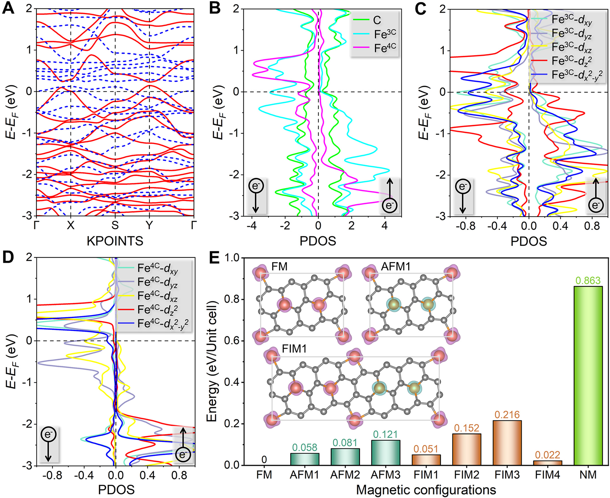
Figure 5. Calculation results about the electronic properties of the ground-state 2D-Fe3C18. (A) Band structure, where the red solid (blue dashed) line represents the majority-spin (minority-spin) channel. (B-D) Projected density of states (PDOS) plots. (E) Energy comparison of nine possible magnetic configurations, where the energy of the FM configuration is set to 0 eV/Unit cell. The insets show the FM, AFM1, and FIM1 configurations. Other magnetic coupling configurations are shown in the Supplementary Materials. The magenta (cyan) isosurface represents the spin-up (spin-down) density. The spin differential density (ρ↑-↓) is calculated as ρ↑-↓ = ρ↑ - ρ↓, where ρ↑ (ρ↓) denotes the spin-up (spin-down) density.


