


fig7
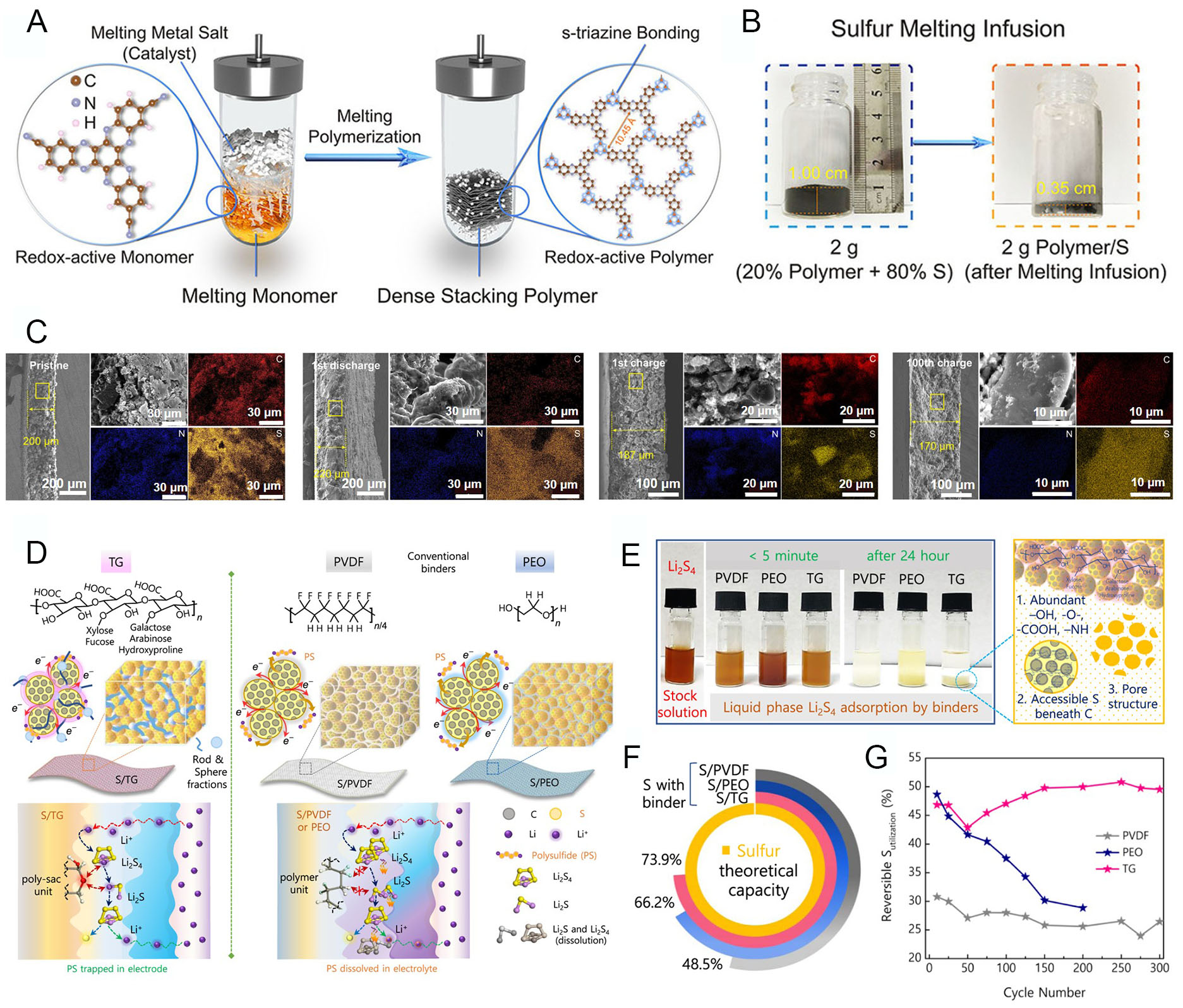
Figure 7. Polymer design for polysulfide shuttle suppression in S cathodes. (A) Schematic of polymer synthesis from monomers. (B) Photographs showing S infusion into dense porous polymer (cooled after 155 °C for 12 h). (C) Electrode thickness changes of polymer/S cathode (15 mg cm-2, delivering 10.5 mAh cm-2 at 1 mA cm-2) for pristine, 1st discharged, 1st charged, and 100th charged states. Reproduced with permission[106]. (D) Schematic illustration of cathode architecture with different binders: TG, PVDF, and PEO. S is loaded into Super P carbon with the respective binder. (E) Static adsorption of liquid-phase polysulfides by pristine PVDF, PEO, and TG binders. (F) S utilization for various binders at C/5 (against the theoretical capacity of S = 1,675 mAh g-1). (G) Reversible S utilization of various electrodes over selected cycle numbers. Reproduced with permission[107].


