


fig10
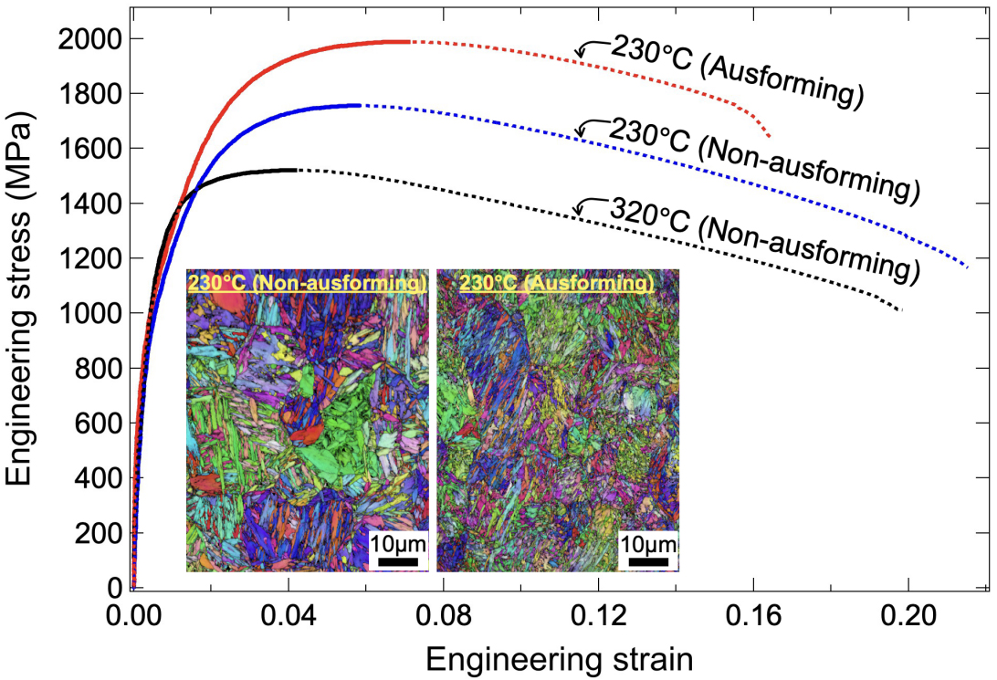
Figure 10. Comparison of engineering stress-strain curves for specimens subjected to AIH and DIH processes at different isothermal holding temperatures. The insets show a comparison of IPF images of the BCC phase in specimens subjected to the AIH and DIH processes treated at 230 °C. IPF: Inverse pole figure; BCC: body-centered cubic; AIH: ausforming and isothermal holding; DIH: direct isothermal holding.


