fig7

Impact of hierarchical martensitic structure on deformation twinning in titanium alloys during additive manufacturing

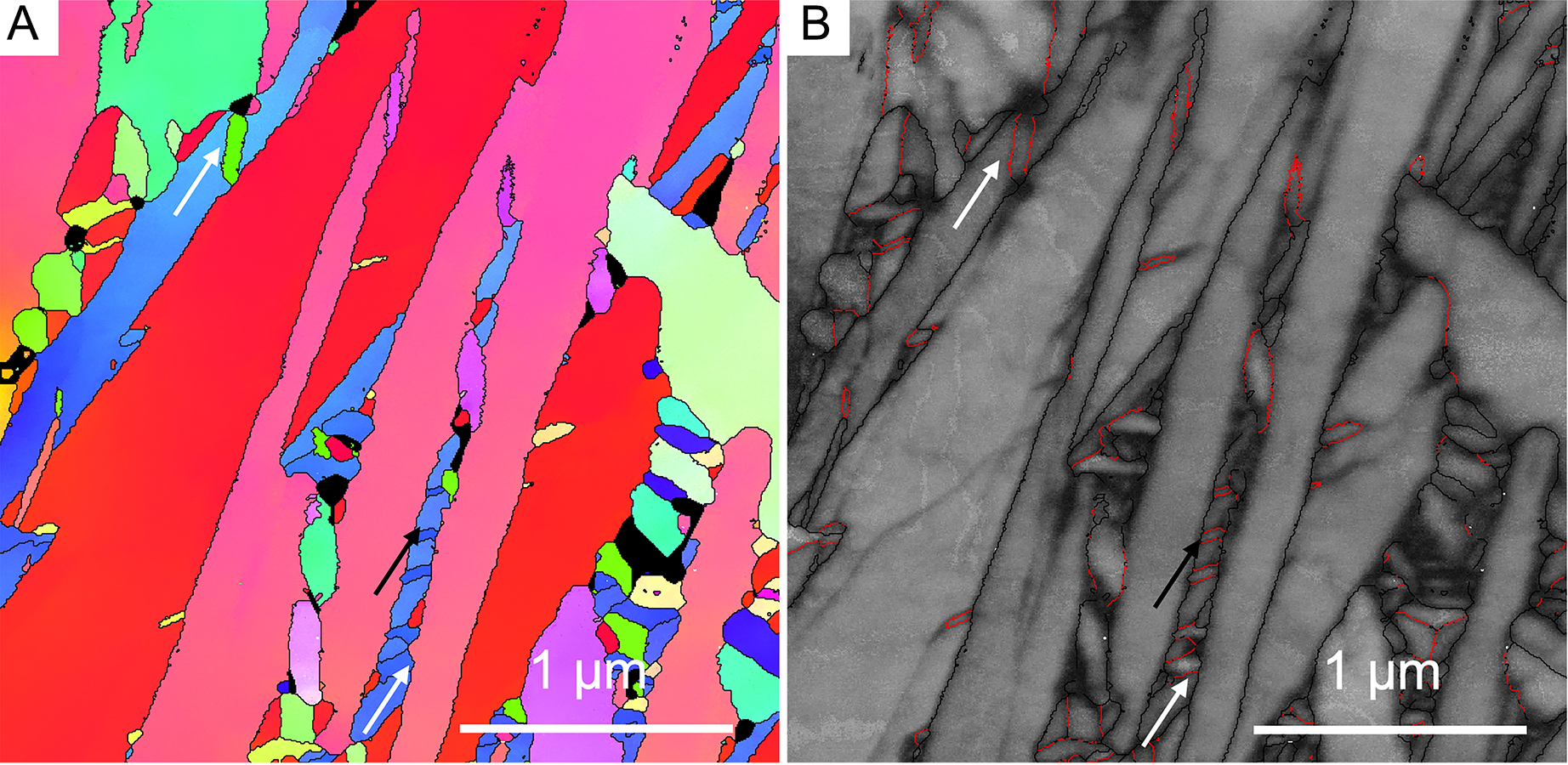
Figure 7. A typical microstructure in a bottom layer of the L-DED Ti-6Al-4V sample. (A) TKD IPF map showing a hierarchical martensitic structure. (B) GB map showing the distribution of GB types. The colour codes for marking different types of GBs are the same as in Figure 1. White and black arrows point to linked twins and non-linked twins, respectively.

Microstructures
ISSN 2770-2995 (Online)

Portico

All published articles are preserved here permanently:

https://www.portico.org/publishers/oae/

Portico

All published articles are preserved here permanently:

https://www.portico.org/publishers/oae/