


fig6
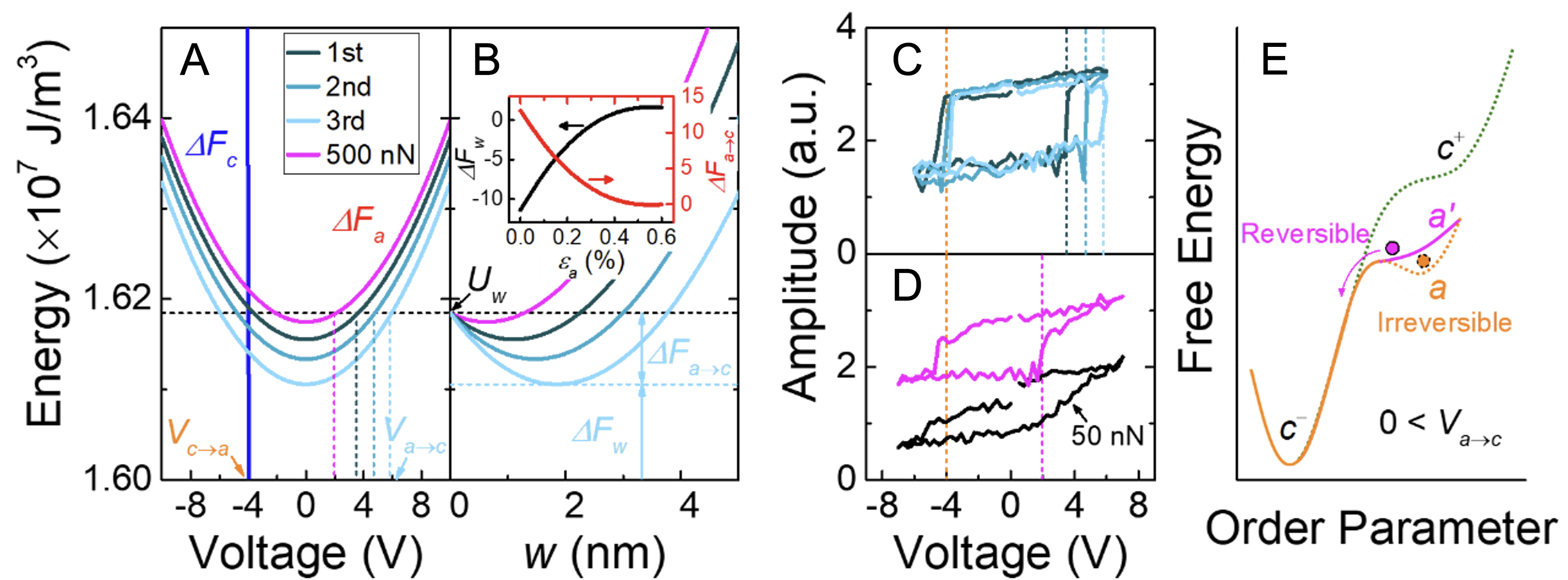
Figure 6. (A) Free energies as a function of applied voltages for newly formed a-domains [ΔFa (V)] during the 1st (dark cyan line), 2nd (medium cyan line), and 3rd (light cyan line) voltage sweeps, together with the tip contact force of 500 nN (magenta line). Corresponding coercive voltages for a- to c-domain switching (Va→c) required to overcome the surface energy (Uw, black dashed line) are indicated; (B) Elastic energy versus a-domain width for the voltage sweeps (same color code as in A). The elastic energy at wa (ΔFw), and the energy barrier for a- to c-domain switching (ΔFa→c) during the 3rd voltage sweep are marked as examples. The inset shows strain (εa) dependent ΔFw (black line, left y-axis) and ΔFa→c (red line, right y-axis). PFM amplitude as a function of voltage for (C) the three voltage sweeps (same color code as in A) and for (D) tip contact forces of 500 nN (magenta line) and 50 nN (black line). Corresponding Va→c for each voltage sweep and tip contact force are indicated and Vc→a (orange dashed line) is shown for comparison. (E) Schematic energy diagram for irreversible (a; orange) and reversible (a’; magenta) a-domains under 0 < Va→c, compared with the transition from c+ (green) to c-. PFM: Piezoelectric force microscopy.


