

fig4
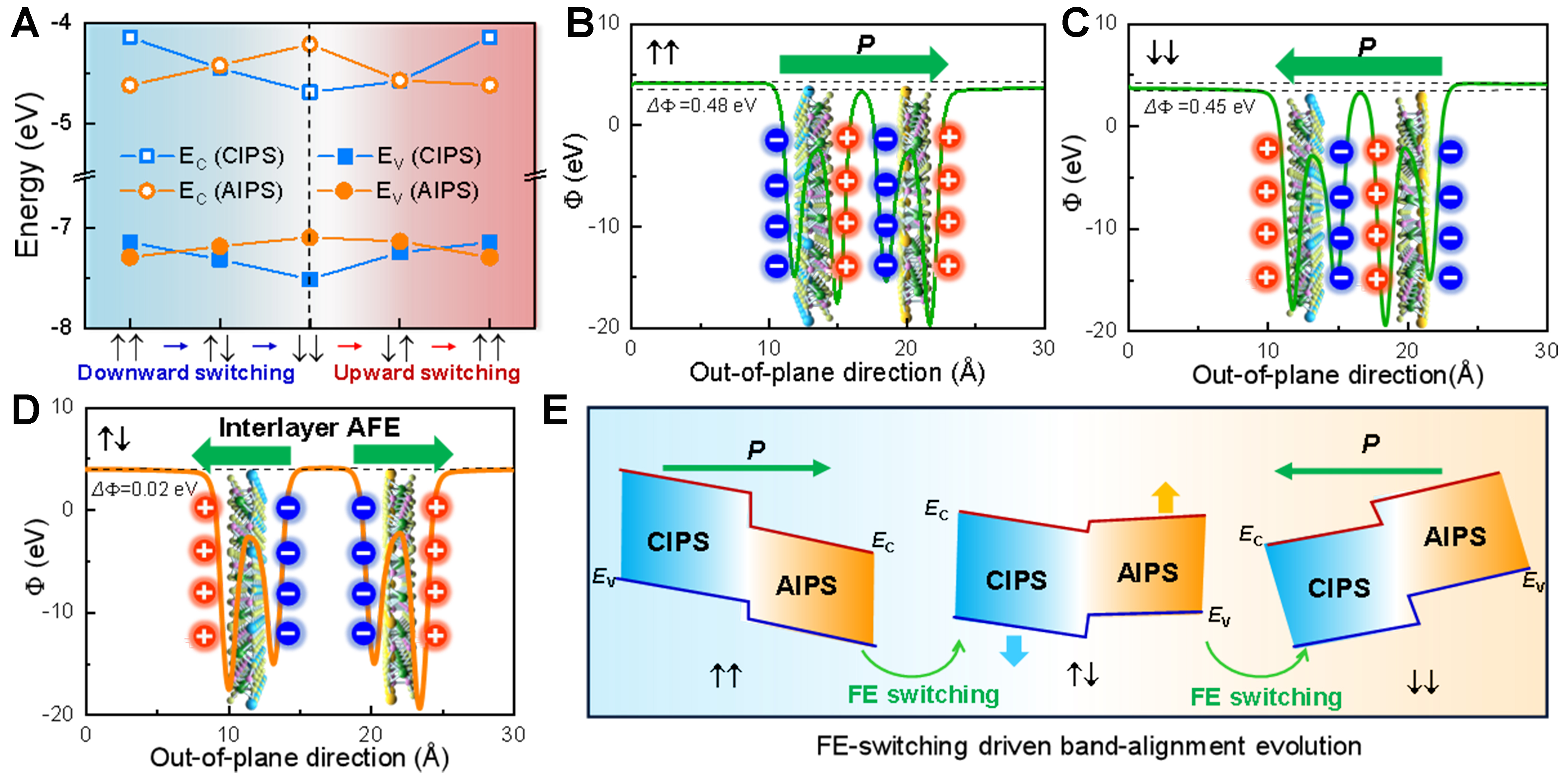
Figure 4. FE polarization effect on the band alignment evolution of 2D CIPS/AIPS VFSH. (A) The variation of EC and EV of CIPS and AIPS layers in the VFSH with the sequential switching of four polarization states; (B-D) Electrostatic potential distribution of CIPS/AIPS VFSH at (B) ↑↑ state, (C) ↓↓ state, and (D) ↑↓ state. The ↑↑ and ↓↓ states correspond to interlayer FE coupling, and ↑↓ and ↓↑ states correspond to interlayer AFE coupling. The arrows denote the polarization direction; (E) The band-alignment evolution in CIPS/AIPS VFSH driven by the switching of polarization states from ↑↑, ↑↓, to ↓↓ state. FE: Ferroelectric; 2D: two-dimensional; CIPS/AIPS: CuInP2S6/AuInP2S6; VFSH: vdW FE semiconductor heterojunction; AFE: antiferroelectric.