



MgF2 surface loading stabilizes the interfacial chemical environment of O3-Type NaNi1/3Fe1/3Mn1/3O2 cathodes for sodium-ion batteries
 0
0 
Abstract
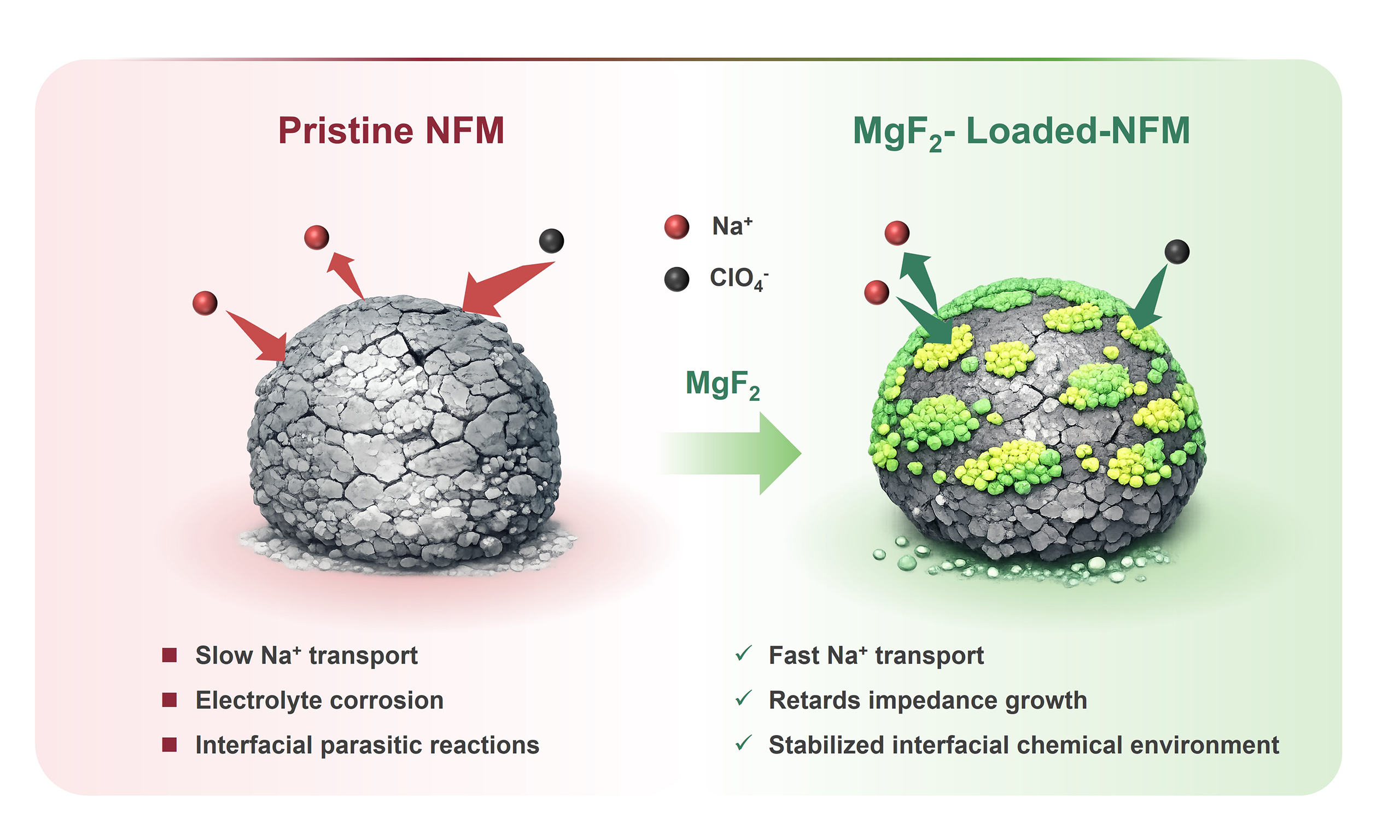
O3-NaNi1/3Fe1/3Mn1/3O2 (NFM) has drawn considerable attention as a cathode material for sodium-ion batteries, but its practical application is restricted by interfacial parasitic reactions, continuous impedance growth, and phase-transition-associated structural instability. Here, a MgF2 surface layer is introduced onto NFM through a post-treatment surface-loading strategy to regulate the interfacial chemical environment of the cathode. The MgF2 loading preserves the O3-type bulk framework and the dominant transition-metal valence states of NFM, while generating a non-uniform Mg/F-enriched surface layer. Among the investigated samples, NFM@1%MgF2 exhibits the best overall electrochemical performance, delivering 103.01 mA h g-1 after 100 cycles at 1C with a capacity retention of 85.65%, achieving 82.09 mA h g-1 at 10C, and retaining 75.17% of its capacity after 300 cycles at 3C. Galvanostatic intermittent titration technique, electrochemical impedance spectroscopy, and post-cycling X-ray photoelectron spectroscopy collectively show that MgF2 loading enhances apparent Na+ transport kinetics, suppresses interfacial side reactions, and retards impedance growth during cycling. Operando X-ray diffraction further reveals that MgF2 does not alter the intrinsic O3-P3-O3 transition sequence of NFM but markedly mitigates the associated structural response. In addition, an NFM@1%MgF2||hard carbon full cell exhibits 85.43% capacity retention after 100 cycles at 1C. These results establish MgF2 surface loading as an effective route for interfacial stabilization in O3-type NFM cathodes and suggest a generalizable strategy for regulating interfacial chemistry in sodium-ion battery cathode materials.
Keywords
INTRODUCTION
With the rapid development of large-scale energy storage technologies, sodium-ion batteries have attracted extensive attention as promising alternatives to lithium-ion batteries owing to their abundant resource availability, low cost, and partial compatibility with existing lithium-ion battery manufacturing infrastructure[1-4]. Among the cathode candidates developed for sodium-ion batteries, layered transition-metal oxides remain a major research focus because of their relatively high operating voltages, high capacities, and mature synthesis routes[5-11]. However, the larger ionic radius of Na+ and the distinctive interfacial chemistry of sodium-ion systems make these materials more susceptible to complex structural evolution, interfacial instability, and accumulated side reactions during Na+ extraction/insertion, thereby limiting their electrochemical performance[12-14]. O3-type NaNi1/3Fe1/3Mn1/3O2 (NFM) has been extensively explored owing to its simple composition, low cost, and comparatively high capacity. Previous studies have shown that NFM can deliver a reversible capacity of approximately 130 mA h g-1 within 2.0-4.0 V and typically undergoes a relatively direct O3-P3-O3 structural evolution, making it a representative O3-type layered oxide cathode[15-17]. Nevertheless, NFM still suffers from several coupled issues. On the one hand, it is sensitive to air and moisture, which can induce Na+ loss and the formation of surface residuals such as Na2CO3[18,19]. On the other hand, the degradation of NFM is governed not by a single failure mode but by the interplay among bulk phase evolution, near-surface structural damage, and interfacial parasitic reactions. Repeated phase-transition-associated stress can progressively disrupt particle integrity, expose fresh reactive surfaces, and continuously alter the chemistry of the cathode electrolyte interphase (CEI), thereby accelerating impedance growth and capacity decay[20-22].
Accordingly, various modification strategies have been developed, including elemental doping, surface coating, interfacial reconstruction, and electrolyte regulation[23-27]. For the NFM system, NaTi2(PO4)3 coatings[28], Na2MoO4 reactive wetting layers[29], composite surface modifications, and electrode-level regulation have all been shown to reduce polarization, retard interfacial degradation, and improve cycling stability and rate capability to varying extents[30-32]. These studies indicate that improving the electrochemical performance of NFM cannot rely solely on bulk structural regulation; simultaneous stabilization of the particle surface and the cathode/electrolyte interface is also required. In recent years, fluoride-related strategies have attracted increasing attention. Reported studies have shown that fluorinated interfacial engineering can promote the formation of a robust NaF-rich CEI, suppress continuous electrolyte decomposition, reduce the accumulation of surface by-products, and alleviate structural perturbations during cycling, thereby enhancing both structural integrity and interfacial stability of layered oxide cathodes[33-37]. Among reported fluoride-related strategies, AlF3 and LaF3 coatings mainly serve as protective fluoride layers to mitigate interfacial side reactions and electrolyte corrosion, while eutectic fluoride salts provide multicomponent fluorinated surface modification. In contrast, direct fluorination or F-doping usually involves lattice-level regulation through partial O/F substitution, which may influence Na+ diffusion channels, phase evolution, and migration barriers[35,38-41]. Compared with these strategies, the role of MgF2, a chemically stable metal fluoride, in O3-type NFM remains insufficiently understood. Previous studies have demonstrated that MgF2 coatings can stabilize the cathode/electrolyte interface[42,43], mitigate side reactions[44,45], and suppress impedance growth[42,45]. However, for NFM, which simultaneously suffers from air sensitivity, interfacial instability, and phase-transition-induced stress, whether MgF2 surface loading can regulate the interfacial environment and further mitigate structural perturbation and impedance growth still requires systematic clarification.
Herein, a non-uniform MgF2 layer was introduced onto the surface of NFM through a post-treatment process. By combining structural characterization, surface chemical analysis, electrochemical evaluation, kinetic analysis, operando X-ray diffraction (XRD), and full-cell validation, the effects of MgF2 on the interfacial chemistry and structural evolution of NFM were systematically investigated. The results reveal that an appropriate MgF2 loading amount preserves the O3-type bulk framework while stabilizing the interfacial chemical environment, retarding impedance growth, and mitigating the phase-transition-associated structural response. This work therefore identifies MgF2 surface loading as a viable strategy for interfacial stabilization in O3-type NFM cathodes and provides a useful design basis for surface-regulated layered oxide cathodes for sodium-ion batteries.
EXPERIMENTAL
Materials synthesis
NFM was prepared through a citric-acid-assisted sol-gel route followed by high-temperature calcination. Stoichiometric amounts of CH3COONa, Mn(CH3COO)2·4H2O, Ni(CH3COO)2·4H2O, and Fe(NO3)3·9H2O were first weighed and dissolved in deionized water to form a mixed metal-salt solution. All reagents were purchased from Macklin and used without further purification. The obtained solution was magnetically stirred (S82-8, Shanghai Zhiwei Electric Appliance Co., Ltd., China) at 400-500 rpm for approximately
Characterization
The elemental ratios were determined by inductively coupled plasma optical emission spectroscopy (ICPOES 730, Agilent, USA). Crystal structures were examined by powder XRD (Malvern Panalytical, Empyrean, Netherlands) using Cu Kα radiation with a wavelength of 1.5405 Å. Data were collected over a 2θ range of 10° to 90° at a voltage of 40 kV and a current of 30 mA. Operando XRD measurements were performed over a scanning range of 10° to 70°. Morphological observations were carried out using scanning electron microscopy (SEM) (TESCAN, LYRA3 GMU, Czech Republic). Transmission electron microscopy (TEM) (Thermo Fisher Scientific, Talos F200X G2, USA) was further used to examine the microstructure and elemental distribution. Surface chemical states were analyzed by X-ray photoelectron spectroscopy (XPS) (Thermo Fisher Scientific, ESCALAB Xi+, USA), and spectral fitting was performed using Avantage software.
Electrochemical measurements
For half-cell tests, the cathode slurry was prepared by mixing the active material, carbon black, and polyvinylidene fluoride (PVDF) at a mass ratio of 8:1:1 in N-methyl-2-pyrrolidone (NMP). The slurry was uniformly cast onto aluminum foil and subsequently vacuum-dried at 120 °C for 10 h to yield the working electrodes, with an active material loading of approximately 2-3 mg cm-2. The electrolyte consisted of 1 M NaClO4 dissolved in an ethylene carbonate/propylene carbonate (1:1 by volume) mixture, supplemented with 5% fluoroethylene carbonate. Sodium metal was used as the negative electrode, and GF/D glass fiber (Whatman) was used as the separator. CR2032 coin cells were assembled in an argon-filled glove box. Galvanostatic charge-discharge (GCD) measurements were performed on a LAND CT2001A (China) battery testing system at 25 °C over the 2.0-4.0 V range. Electrochemical impedance spectroscopy (EIS) and cyclic voltammetry (CV) were performed on an Autolab (PGSTAT302N, Switzerland) electrochemical workstation. The impedance spectra were collected over a frequency range of 0.01 Hz-1 MHz. Galvanostatic intermittent titration technique (GITT) measurements were conducted at 0.1C, corresponding to 13 mA g-1, with a 10 min current pulse followed by a 2 h relaxation period. For the full cells, the anode slurry was prepared by mixing hard carbon, carbon black, and PVDF at a mass ratio of 9:1:1 in NMP. The slurry was uniformly cast onto aluminum foil and subsequently vacuum-dried at 90 °C for 10 h. Before full-cell assembly, the hard carbon anode was pre-sodiated by direct contact with metallic sodium. The N/P ratio, based on reversible capacity, was controlled at 1.05.
RESULTS AND DISCUSSION
Materials characterization
To determine the elemental composition, inductively coupled plasma optical emission spectroscopy (ICP-OES) was conducted on the powder samples, and the results are summarized in Supplementary Table 1. No Mg signal was detected in pristine NFM. By contrast, the Mg atomic fractions in
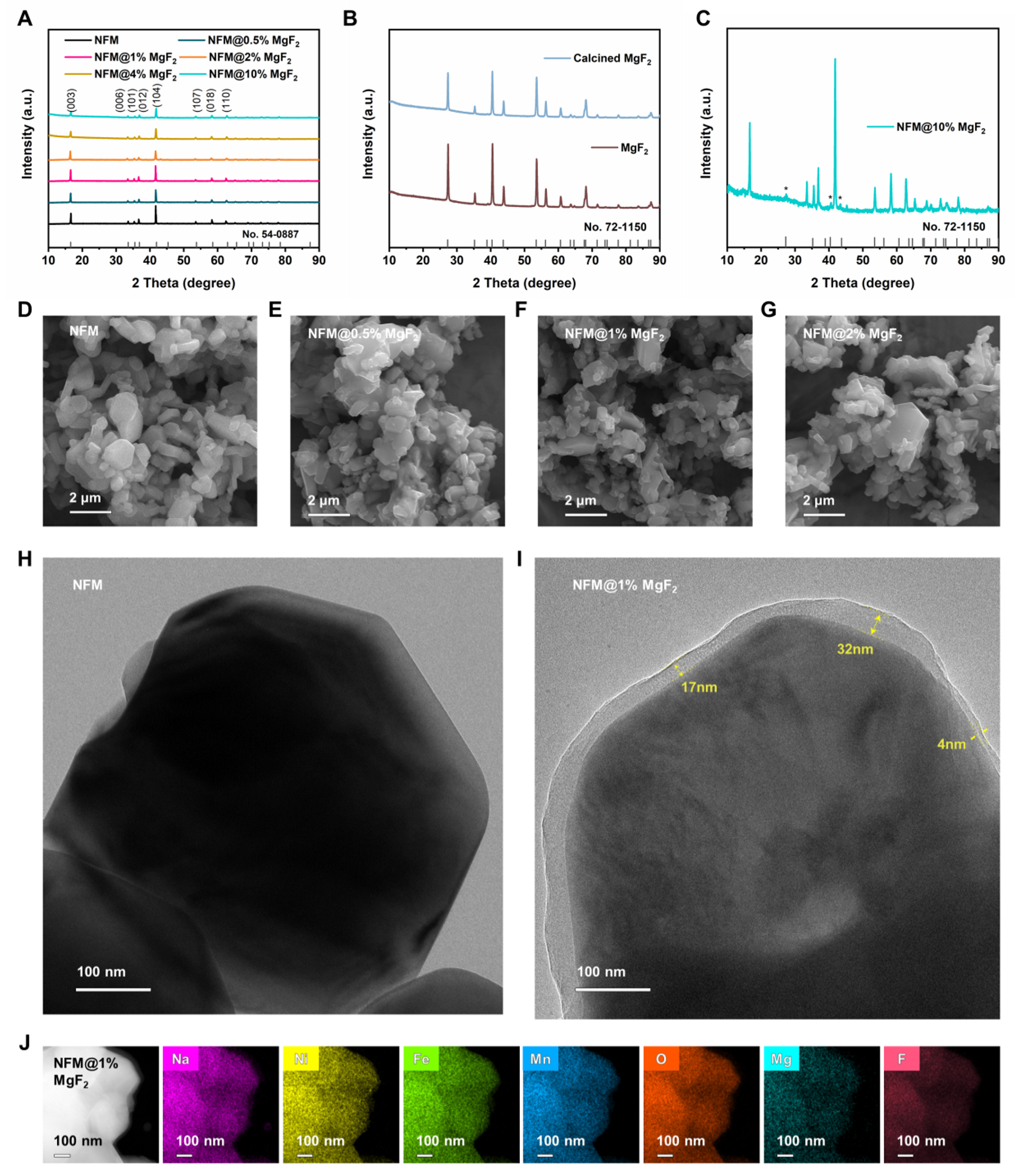
Figure 1. Morphological and structural characterization of the prepared samples. (A) Powder XRD patterns of pristine NFM and MgF2-loaded at different loading amounts, (B) XRD patterns of MgF2 before and after calcination, (C) XRD patterns of NFM@10%MgF2 sample. (D-G) SEM images of pristine NFM,
Figure 1D-G show SEM images of pristine NFM and MgF2-loaded samples with different loading amounts. Pristine NFM mainly consists of irregular block-like or platelet-like primary particles aggregated into micron-sized secondary particles. After MgF2 treatment,
TEM reveals differences in surface microstructure before and after modification. As shown in Figure 1H, pristine NFM exhibits a relatively clean and smooth particle edge without an obvious additional outer layer. In contrast, an additional surface layer with a contrast distinct from that of the bulk can be observed at the particle edge of the modified sample [Figure 1I], indicating the formation of a discernible surface layer after the loading treatment. The thickness of this layer varies considerably across locations, with a minimum of about 4 nm and a local maximum of approximately 32 nm, suggesting that it is not a continuous and uniform dense coating film but rather a non-uniform surface layer enriched with Mg/F species. The non-uniform Mg/F-enriched surface layer can be understood as a surface configuration that balances interfacial protection and Na+ transport. MgF2 is chemically stable and can protect the cathode surface from electrolyte attack and resistive surface-film growth, but it is not an intrinsically fast ionic/electronic conductor[42,48,49]. Therefore, an excessively thick and fully dense MgF2 layer may hinder Na+ transfer across the cathode/electrolyte interface[50,51]. In this work, the locally thicker MgF2-rich regions may help passivate highly reactive surface sites and suppress parasitic interfacial reactions, while thinner or less-covered regions may shorten Na+ transport pathways and avoid forming a fully dense, transport-blocking shell. This protection-transport balance is consistent with the optimized electrochemical performance of NFM@1%MgF2. Energy-dispersive X-ray spectroscopy (EDS) mapping was further performed to examine the elemental distribution [Supplementary Figure 1, Figure 1J]. For pristine NFM, Na, Ni, Fe, Mn, and O are homogeneously distributed throughout the particle region, indicating the uniform composition of the NFM host. For the MgF2-loaded sample, Mg and F signals are clearly detected, while Na, Ni, Fe, Mn, and O remain uniformly distributed overall, and the Mg and F signals show good spatial correspondence. Together with the additional surface layer observed by TEM, these results confirm that the introduced Mg and F are closely associated with the surface-loaded layer, demonstrating the successful introduction of MgF2 onto the surface of NFM particles in terms of elemental composition, microstructure, and spatial distribution. In addition, SEM images show that the MgF2 powder consists of irregular particles of approximately
To further elucidate the surface chemical composition and valence states after MgF2 loading, XPS measurements were carried out on NFM and NFM@1%MgF2. As shown in the XPS survey spectra in Supplementary Figure 3, NFM@1%MgF2 retains the intrinsic signals of Na 1s, Ni 2p, Fe 2p, Mn 2p, and O 1s, while additional Mg 1s, F 1s, and Mg Auger peaks appear, which are absent in pristine NFM. This result confirms the successful introduction of Mg- and F-containing species onto the sample surface. Combined with the aforementioned XRD, ICP, and TEM results, the introduction of MgF2 can thus be understood primarily as the formation of a Mg/F-enriched surface layer rather than a significant bulk compositional reconstruction. At the same time, the persistence of clear matrix-element signals suggests that the fluorinated layer is not an excessively thick and fully continuous dense shell. Rather, it remains a relatively thin and non-uniform surface-loaded layer. High-resolution XPS spectra [Figure 2] further reveal that MgF2 loading does not induce an obvious change in the dominant surface valence states of the transition metals in NFM. The Ni 2p, Fe 2p, and Mn 2p spectra show nearly identical peak positions and satellite features before and after modification. The splitting energy of Mn 3s is about 4.75 eV, indicating that Mn remains mainly in the Mn4+ state. Therefore, the surface of NFM@1%MgF2 still shows dominant Ni2+/Fe3+/Mn4+ surface states, suggesting that MgF2 does not significantly alter the intrinsic redox-active centers of NFM[47,52,53]. In contrast, the newly emerged Mg 1s and F 1s signals in NFM@1%MgF2 provide direct chemical evidence for the surface modification. Specifically, the F 1s peak at approximately 684.05 eV and the Mg 1s peak at approximately 1,304.15 eV can be assigned to Mg/F-containing fluoride species, confirming the formation of a Mg/F-enriched surface layer on NFM@1%MgF2[44,45]. On this basis, the role of MgF2 in the present system is more reasonably understood as the regulation of the surface chemical environment rather than the modification of the bulk framework or intrinsic transition-metal redox chemistry. This distinction is critical for the subsequent mechanistic discussion because it confines the major function of MgF2 to the surface/interface region, where the key electrochemical instability of O3-type NFM is expected to originate.
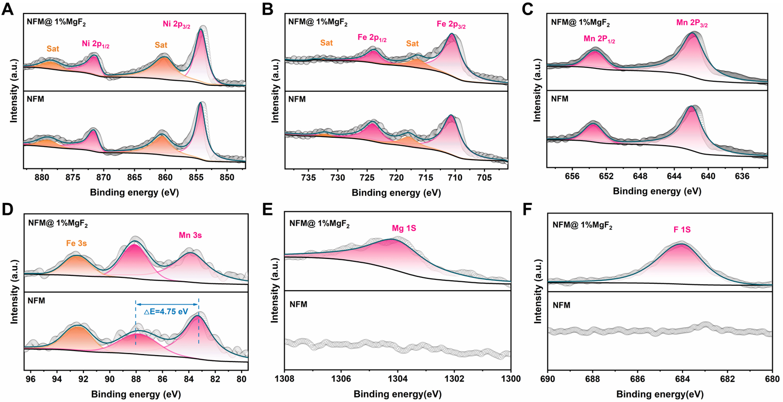
Figure 2. High-resolution XPS spectra of pristine NFM and NFM@1%MgF2. (A) Ni 2p, (B) Fe 2p, (C) Mn 2p, (D) Mn 3s, (E) Mg 1s and
Overall, the ICP-OES, XRD, SEM, TEM, EDS, and XPS results demonstrate that MgF2 does not significantly alter the bulk stoichiometry or the O3-type layered framework of NFM, but instead leads to the formation of a Mg/F-enriched surface layer with locally non-uniform thickness. This structural feature provides a direct basis for understanding the subsequent interfacial and electrochemical behavior. In the present system, the non-uniformity of the MgF2 surface layer should not be regarded as an imperfection. Instead, it is likely to be functionally beneficial. A non-uniform and discontinuous surface-loaded layer may preferentially protect highly reactive surface sites while avoiding the severe Na+ transport penalty commonly associated with overly thick and continuous coatings. This structure-property relationship is consistent with the central idea of this work, namely that proper regulation of the cathode interfacial chemical environment can improve electrochemical stability without sacrificing the intrinsic structural advantages of the O3-type cathode.
Electrochemical measurements
The effect of MgF2 surface loading on the electrochemical properties was evaluated at 25 °C within 2.0-4.0 V. Figure 3A and B, Supplementary Figure 4 display the GCD profiles of NFM,
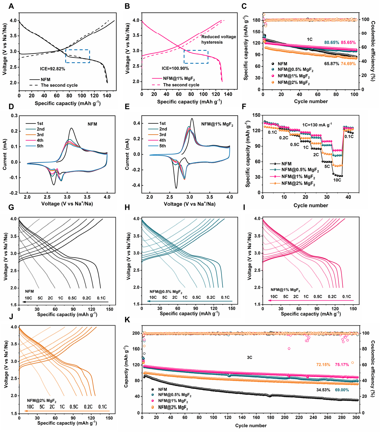
Figure 3. Electrochemical behaviors of pristine NFM and MgF2-loaded NFM electrodes measured between 2.0 and 4.0 V. (A and B) GCD profiles of pristine NFM and NFM@1%MgF2 of the initial two cycles of 0.1C, the second cycle is dashed line. The blue dashed lines indicate the alleviated voltage hysteresis. (C) Cycling performance of 1C. (D and E) CV curves of pristine NFM and NFM@1%MgF2 recorded during the 5 cycles at a scanning speed at 0.1 mV s-1. (F) Rate capability from 0.1C to 10C. (G-J) GCD curves collected at 0.1-10C for the rate-performance test. (K) Long-cycling performance at 3C.
To further analyze polarization and electrochemical reversibility during the initial cycling stage, CV measurements were performed on NFM and NFM@1%MgF2 at a scan rate of 0.1 mV s-1 for the first five cycles [Figure 3D and E]. In the first cycle, pristine NFM exhibits a main pair of redox peaks at around 3.106/2.664 V, which can be mainly assigned to the Ni2+/Ni3+ redox couple, while the weak peak or shoulder near 4.0 V can be attributed to the onset of Ni3+/Ni4+ and Fe3+/Fe4+ oxidation at higher potentials[17,55]. Compared with pristine NFM, NFM@1%MgF2 shows oxidation/reduction peak positions at 3.058/2.661 V, with the peak separation decreasing from 0.442 to 0.397 V, indicating reduced electrochemical polarization after MgF2 loading. In addition, the CV curves of NFM@1%MgF2 exhibit a higher degree of overlap in subsequent cycles. This feature suggests improved reaction reversibility and less pronounced polarization evolution during early cycling. Such behavior further supports the idea that MgF2 mainly acts by stabilizing the local interfacial environment, thereby allowing the layered host to operate in a more reversible manner.
The rate performance of all samples was further evaluated over the range of 0.1-10C. As shown in Figure 3F, although the capacities of all samples decrease to varying extents with increasing current density, NFM@1%MgF2 consistently exhibits the best high-rate response. At 10C, the discharge capacities of NFM,
Mechanistic investigation
To further clarify the influence of MgF2 surface loading on reaction kinetics and interfacial evolution during cycling, GITT, EIS, and post-cycling XPS analyses were performed on NFM and NFM@1%MgF2 electrodes. It should be noted that the Na+ diffusion coefficients derived from GITT reflect the apparent transport kinetics during charge and discharge. These values are influenced not only by bulk Na+ diffusion but also by interfacial film states and electrochemical polarization. Therefore, the present discussion focuses on the improvement of Na+ transport kinetics during operation rather than directly attributing the GITT results to a reduced intrinsic Na+ migration barrier in the pristine NFM lattice. As shown in Figure 4A and B, the GITT profiles of NFM and NFM@1%MgF2 are generally similar after 2 cycles, indicating comparable Na-storage pathways for the two samples. However, the corresponding diffusion coefficient distributions reveal that NFM@1%MgF2 exhibits higher logD values over most of the charge/discharge range. The box plots in
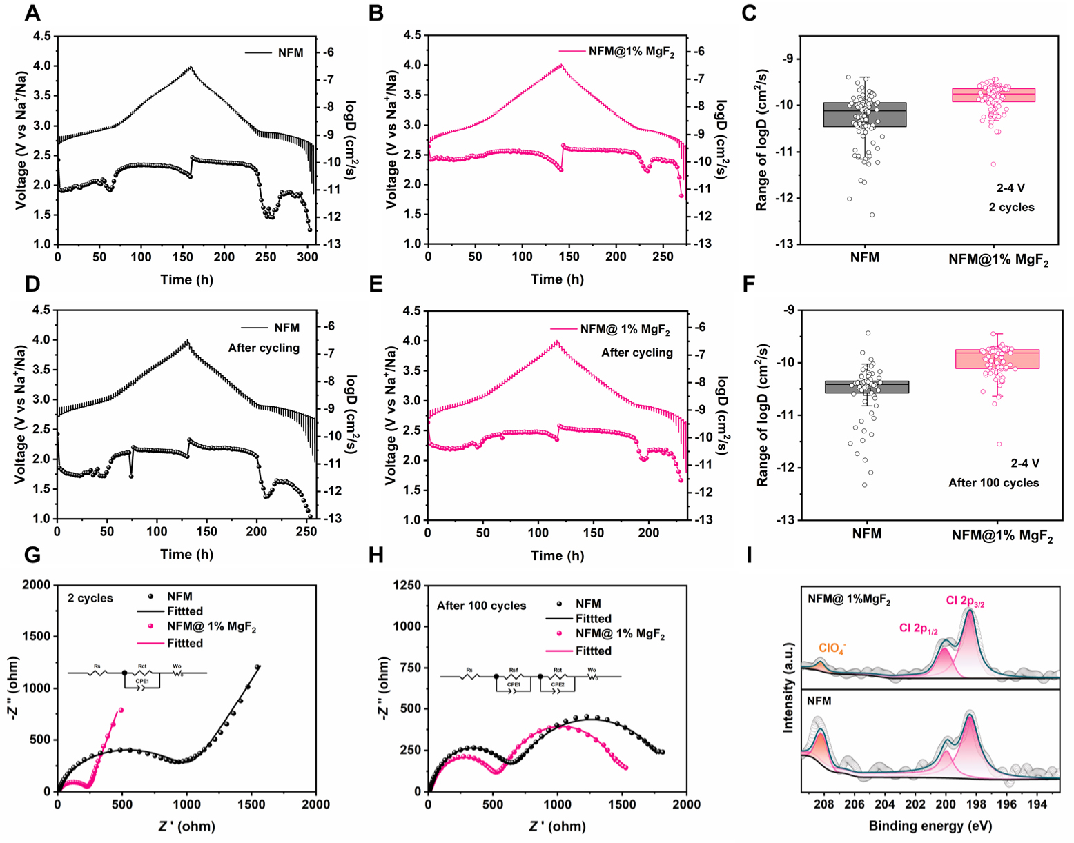
Figure 4. Electrochemical characterization and interfacial evolution of pristine NFM and NFM@1%MgF2. (A and B) Representative GITT and calculated Na+ diffusion coefficients of pristine NFM and NFM@1%MgF2 after 2 cycles. (C, F) Box plots of the logD values calculated from the corresponding GITT steps in (A and B) and (D and E), respectively. The scattered points represent individual logD values obtained from valid GITT steps within the corresponding representative GITT measurement, rather than from independent repeated experiments. The boxes indicate the 25-75th percentile range, the horizontal lines indicate the median values, the square symbols indicate the mean values, and the whiskers indicate the minimum-maximum range. The sample size n represents the number of valid GITT-derived logD values used for each box plot. (D and E) Representative GITT and calculated Na+ diffusion coefficients of pristine NFMand NFM@1%MgF2 after 100 cycles. (G and H) Representative EIS spectrum together with the fitting results of pristine NFM and NFM@1%MgF2 with the inset showing the equivalent circuit for fitting. (I) Cl 2p XPS spectra of cycled pristine NFM and NFM@1%MgF2 after 100 cycles.
To validate the above conclusion from the perspective of interfacial impedance, EIS spectra of the electrodes after 2 and 100 cycles at open-circuit potential were fitted, and the results are shown in Figure 4G and H, Supplementary Table 3. In the equivalent circuit, Rs represents the solution/ohmic resistance, Rsf corresponds to the surface film resistance, Rct is the charge-transfer resistance, and the low-frequency sloping line is associated with the Warburg diffusion process[6,59]. After two activation cycles, the Rs values of NFM and NFM@1%MgF2 are 6.345 and 5.252 Ω, respectively, indicating a negligible difference in bulk electrolyte resistance. At the same time, Rct decreases dramatically from 1,016 Ω for NFM to 191.1 Ω for NFM@1%MgF2, indicating much faster charge transfer at the electrode/electrolyte interface after MgF2 loading. After 100 cycles, both samples exhibit obvious increases in surface-film-related impedance, indicating the gradual formation and thickening of the interfacial layer. Moreover, the Rsf and Rct values of NFM@1%MgF2 remain at 540.8 and 969.8 Ω, respectively, both of which are lower than those of pristine NFM, which reach 607.2 and 1,305 Ω. These results indicate that although MgF2 cannot completely prevent impedance growth, it can effectively slow the growth rate and maintain lower interfacial reaction resistance and charge-transfer resistance after long-term cycling. Therefore, the role of MgF2 is not to create a perfectly inert surface, which would be unrealistic under repeated electrochemical operation. Instead, its function is to regulate interfacial evolution so that the resistance increases more slowly and remains at a lower level. Such behavior is expected from an effective interfacial stabilization strategy. TEM images of the cycled NFM@1%MgF2
To further clarify the CEI chemistry after cycling, high-resolution F 1s, C 1s, O 1s, and Na 1s XPS spectra were collected for the cycled NFM and NFM@1%MgF2 electrodes [Supplementary Figure 6]. In the F 1s spectra, cycled NFM shows both Na-F and C-F components, indicating the coexistence of inorganic fluoride species and fluorinated organic decomposition products. In contrast, NFM@1%MgF2 is dominated by the Na-F/Mg-F-related inorganic fluoride component, while the C-F contribution is significantly weakened. The C 1s and O 1s spectra further show weakened C-F and O-C=O-related contributions after MgF2 loading, suggesting suppressed accumulation of fluorinated organic species and modified carbonate/oxygenated surface chemistry. The Na 1s spectra mainly show broad Na-containing signals and are used as supporting evidence for Na-containing surface species. The Cl 2p XPS spectra after 100 cycles [Figure 4I] provide further evidence for the interfacial chemical evolution. Both samples exhibit Cl 2p doublets at about 198-200 eV[60], together with ClOx--related signals in the higher binding-energy region[60,61]. Compared with cycled NFM, NFM@1%MgF2 shows clearly weakened high-binding-energy ClOx--related peaks and an overall lower Cl signal intensity. This result indicates that a smaller amount of electrolyte-derived chlorine-containing species accumulates on the cycled surface of the MgF2-loaded sample. Combined with the lower Rsf and Rct values, these XPS results suggest that MgF2 loading suppresses continuous electrolyte side reactions at high potentials and mitigates the deposition of chlorine-containing decomposition or residual products on the cathode surface, thereby stabilizing the interfacial chemical environment. Overall, the GITT, EIS, and post-cycling XPS results demonstrate that the beneficial effect of MgF2 on NFM is mainly manifested in interface-dominated kinetic optimization. Rather than reconstructing the intrinsic bulk diffusion mechanism of NFM, MgF2 stabilizes the particle/electrolyte interface, suppresses side reactions, and retards impedance growth, thereby sustaining Na+ transport efficiency during cycling and ultimately supporting the improved rate capability and cycling stability observed above.
To further understand the role of MgF2 surface loading in structural evolution, operando XRD measurements were performed on NFM and NFM@1%MgF2 during the first cycle at 0.1C within 2.0-4.0 V. As shown in Figure 5A and B, both samples display clear and reversible peak shifts during the initial charge/discharge process. The (003), (006), (101), and (102) reflections evolve synchronously with Na+ extraction and insertion, indicating that the two samples follow similar layered structural evolution pathways within this voltage window. According to the reported structural evolution behavior of NFM, this process can be assigned to the O3-P3-O3 phase transition[22,62]. Notably, the MgF2-modified sample exhibits a smaller peak shift amplitude. During the O3 → P3 transition, the (003) peak shift of NFM reaches approximately 1.05°, whereas that of NFM@1%MgF2 is only 0.84°. This indicates that MgF2 does not alter the fundamental phase-transition type of NFM but rather mitigates the phase-transition-associated structural response. A similar tendency is also observed for the (006), (101), and (102) reflections, all of which exhibit more moderate migration behavior in the MgF2-loaded sample. The operando XRD results also bridge the structural and interfacial observations described above. Once the interfacial chemical environment becomes more stable, the host lattice can undergo the same intrinsic phase transition under less severe interfacial perturbation. Conversely, once the phase-transition-associated structural response is moderated, the probability of generating highly reactive fresh surfaces is reduced. In this sense, interfacial stabilization and structural stabilization are not independent. They reinforce each other and jointly contribute to the improved electrochemical stability of NFM@1%MgF2.
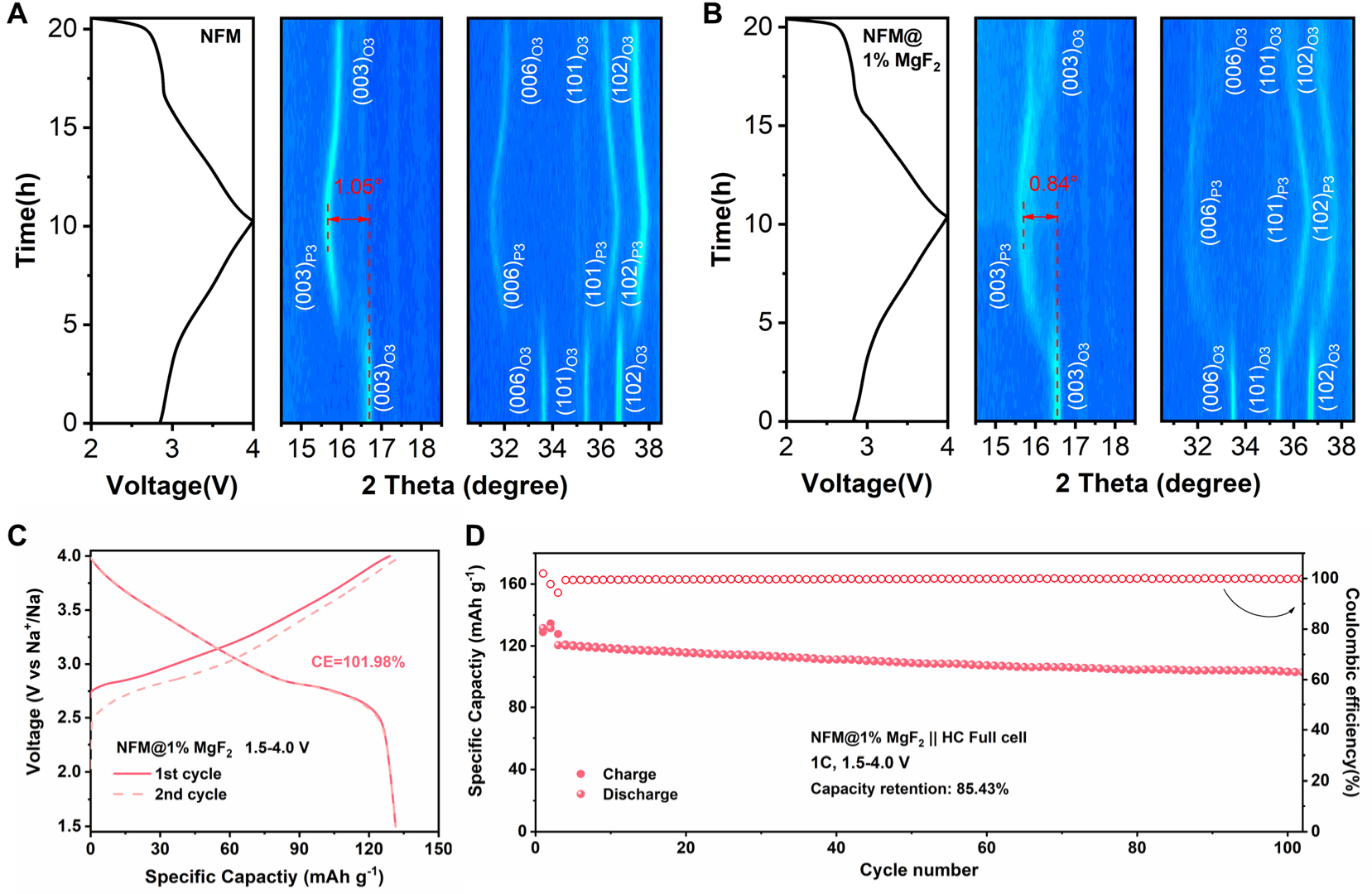
Figure 5. Operando XRD analysis of pristine NFM and NFM@1%MgF2 during the initial charge-discharge process at 0.1C within 2.0-4.0 V, together with the electrochemical performance of the corresponding full cell. (A and B) Charge-discharge profiles and corresponding operando XRD patterns of the NFM and NFM@1%MgF2 electrodes. (C) Initial two-cycle capacity-voltage profiles of the NFM@1%MgF2||HC full cell at 0.1 C in the voltage range of 1.5-4.0 V. The specific capacity is calculated based on the mass of cathode materials. (D) Cycling performance of the NFM@1%MgF2||HC full cell at 1C for 100 cycles.
To evaluate the practical applicability of this interfacial regulation strategy, full cells were assembled using hard carbon (HC) as the anode. First, the HC half-cell exhibits stable Na-storage behavior within 0.01-2.0 V, retaining 95.30% of its capacity after 100 cycles at 1C [Supplementary Figure 7], which confirms the good cycling stability of the employed HC anode and provides a reliable basis for subsequent full-cell evaluation. Based on this, the charge/discharge curves for the initial two cycles of the NFM@1%MgF2||HC full cell within 1.5-4.0 V are shown in Figure 5C, demonstrating stable voltage profiles and good initial reversibility. More importantly, after 100 cycles, the capacity retention of the NFM@1%MgF2||HC full cell reaches 85.43% at 1C
CONCLUSIONS
In summary, MgF2 surface loading provides an effective means to stabilize the interfacial chemical environment of O3-type NFM cathodes. The introduced MgF2 layer preserves the bulk O3 framework while forming a non-uniform Mg/F-enriched surface region. The optimized NFM@1%MgF2 cathode exhibits improved cycling stability and rate capability, slower impedance growth, and a mitigated phase-transition-associated structural response. The improved performance in both half-cell and full-cell configurations indicates that the beneficial effect of MgF2 mainly arises from interfacial stabilization. This work highlights fluoride surface loading as a viable strategy for stabilizing O3-type layered oxide cathodes for sodium-ion batteries.
DECLARATIONS
Authors’ contributions
Visualization, manuscript drafting, experiments: Dong, L.
Data curation: Pan, K.; Zhou, S.
Investigation: Ni, W.
Technical and material support: Limphirat, W.; Li, Z.
Supervision, writing - review and editing: Chen, Q.; Wang, L.; Dou, H.; Pei, Y.
All authors discussed the results and contributed to the final version of the paper.
Availability of data and materials
The original contributions presented in this study are included in the article/Supplementary Material. Further inquiries can be directed to the corresponding author(s).
AI and AI-assisted tools Statement
During the preparation of this work, the AI tool ChatGPT image generation tool (OpenAI, version GPT-5.4, released 2026-03-05) was used solely to generate part of the particle elements in the Graphical Abstract. The tool did not influence the study design, data collection, analysis, interpretation, or the scientific content of the work. All authors take full responsibility for the accuracy, integrity, and final content of the manuscript.
Financial support and sponsorship
The work was supported by the National Key Research and Development Program of China (2023YFB2405800), National Natural Science Foundation Funded Project (52302216, 52573326, 52573245, 52372199), Natural Science Foundation of Guangdong Province (2024A1515012694, 2025A1515010063), Guangdong Provincial Pearl River Talents Program (2023QN10C221), Shenzhen Science and Technology Innovation Committee (JCYJ20250604145604006), Zhuhai Basic and Applied Basic Research Foundation (2320004002688), Shenzhen Longhua Science and Technology Innovation Special Funding Project (Industrial Sci-Tech Innovation Center of Low-Altitude Intelligent Networking).
Conflicts of interest
All authors declared that there are no conflicts of interest.
Ethical approval and consent to participate
Not applicable.
Consent for publication
Not applicable.
Copyright
© The Author(s) 2026.
Supplementary Materials
REFERENCES
1. Dunn, B.; Kamath, H.; Tarascon, J. Electrical energy storage for the grid: a battery of choices. Science 2011, 334, 928-35.
2. Hwang, J.; Myung, S.; Sun, Y. Sodium-ion batteries: present and future. Chem. Soc. Rev. 2017, 46, 3529-614.
3. Tarascon, J. Na-ion versus Li-ion batteries: complementarity rather than competitiveness. Joule 2020, 4, 1616-20.
4. Yabuuchi, N.; Kubota, K.; Dahbi, M.; Komaba, S. Research development on sodium-ion batteries. Chem. Rev. 2014, 114, 11636-82.
5. Gao, R.; Zheng, Z.; Wang, P.; Wang, C.; Ye, H.; Cao, F. Recent advances and prospects of layered transition metal oxide cathodes for sodium-ion batteries. Energy. Storage. Mater. 2020, 30, 9-26.
6. Kim, S. W.; Seo, D. H.; Ma, X.; Ceder, G.; Kang, K. Electrode materials for rechargeable sodium-ion batteries: potential alternatives to current lithium-ion batteries. Adv. Energy. Mater. 2012, 2, 710-21.
7. Nayak, P. K.; Yang, L.; Brehm, W.; Adelhelm, P. From lithium-ion to sodium-ion batteries: advantages, challenges, and surprises. Angew. Chem. Int. Ed. 2017, 57, 102-20.
8. Ma, Q.; Yuan, T.; Li, M.; et al. Bromine-triggered anion redox and strain buffering boost layered oxide cathodes for sodium-ion batteries. eScience 2026, 100586.
9. Ren, H.; Li, Y.; Ni, Q.; Bai, Y.; Zhao, H.; Wu, C. Unraveling anionic redox for sodium layered oxide cathodes: breakthroughs and perspectives. Adv. Mater. 2022, 34, 2106171.
10. Ren, Q.; Pei, Y.; Xiang, Y.; et al. Out-of-plane symmetry design arrests structural evolution in layered-type framework for sustainable sodium shuttling. J. Am. Chem. Soc. 2026, 148, 10356-65.
11. Xiang, X.; Zhang, K.; Chen, J. Recent advances and prospects of cathode materials for sodium-ion batteries. Adv. Mater. 2015, 27, 5343-64.
12. Delmas, C.; Carlier, D.; Guignard, M. The layered oxides in lithium and sodium-ion batteries: a solid-state chemistry approach. Adv. Energy. Mater. 2020, 11, 2001201.
13. Han, M. H.; Gonzalo, E.; Singh, G.; Rojo, T. A comprehensive review of sodium layered oxides: powerful cathodes for Na-ion batteries. Energy. Environ. Sci. 2015, 8, 81-102.
14. Kubota, K.; Kumakura, S.; Yoda, Y.; Kuroki, K.; Komaba, S. Electrochemistry and solid-state chemistry of NaMeO2 (Me = 3d transition metals). Adv. Energy. Mater. 2018, 8, 1703415.
15. Kim, D.; Lee, E.; Slater, M.; Lu, W.; Rood, S.; Johnson, C. S. Layered Na[Ni1/3Fe1/3Mn1/3]O2 cathodes for Na-ion battery application. Electrochem. Commun. 2012, 18, 66-9.
16. Wang, H.; Liao, X.; Yang, Y.; Yan, X.; He, Y.; Ma, Z. Large-scale synthesis of NaNi1/3Fe1/3Mn1/3O2 as high performance cathode materials for sodium ion batteries. J. Electrochem. Soc. 2016, 163, A565-70.
17. Xie, Y.; Wang, H.; Xu, G.; et al. In operando XRD and TXM study on the metastable structure change of NaNi1/3Fe1/3Mn1/3O2 under electrochemical sodium-ion intercalation. Adv. Energy. Mater. 2016, 6, 1601306.
18. Sun, Y.; Wang, H.; Meng, D.; et al. Degradation mechanism of O3-type NaNi1/3Fe1/3Mn1/3O2 cathode materials during ambient storage and their in situ regeneration. ACS. Appl. Energy. Mater. 2021, 4, 2061-7.
19. Yang, Y.; Wang, Z.; Du, C.; et al. Decoupling the air sensitivity of Na-layered oxides. Science 2024, 385, 744-52.
20. Ji, P.; Lei, X.; Wang, J.; et al. Unveiling the structural and chemical evolution of layered oxide cathode for Na-ion batteries induced by water vapor. Adv. Funct. Mater. 2024, 34, 2410485.
21. Yang, X.; Zhang, L.; Liu, G.; et al. Phase transition modulated by grain size and lattice distortion in layered transition metal oxide for sodium-ion batteries. ACS. Appl. Mater. Interfaces. 2024, 16, 40805-13.
22. Zhao, X.; Zhang, L.; Wang, X.; et al. Deciphering cycling voltage-dependent failures of O3-layered cathode for sodium ion battery. J. Mater. Chem. A. 2024, 12, 11681-90.
23. Dong, L.; Wu, W.; Xu, Z.; et al. Nb-doped NaNi1/3Fe1/3Mn1/3O2 and its high-voltage performance as sodium-ion battery cathode. J. Power. Sources. 2025, 640, 236701.
24. Mu, L.; Xu, S.; Li, Y.; et al. Prototype sodium-ion batteries using an air-stable and Co/Ni-free O3-layered metal oxide cathode. Adv. Mater. 2015, 27, 6928-33.
25. Song, T.; Chen, L.; Gastol, D.; et al. High-voltage stabilization of O3-type layered oxide for sodium-ion batteries by simultaneous tin dual modification. Chem. Mater. 2022, 34, 4153-65.
26. Yao, H.; Wang, P.; Gong, Y.; et al. Designing air-stable O3-type cathode materials by combined structure modulation for Na-Ion batteries. J. Am. Chem. Soc. 2017, 139, 8440-3.
27. Yuan, T.; Li, P.; Sun, Y.; et al. Refining O3-type Ni/Mn-based sodium-ion battery cathodes via “atomic knife” achieving high capacity and stability. Adv. Funct. Mater. 2024, 35, 2414627.
28. Zhao, S.; Shi, Q.; Qi, R.; et al. NaTi2(PO4)3 modified O3-type NaNi1/3Fe1/3Mn1/3O2 as high rate and air stable cathode for sodium-ion batteries. Electrochim. Acta. 2023, 441, 141859.
29. Kim, M.; Choi, M.; Choi, W. Boosting the electrochemical performance and moisture stability of O3-type NaNi1/3Fe1/3Mn1/3O2 cathodes using novel Na2MoO4 coatings prepared via a polyvinylpyrrolidone-anchored complex coating process. J. Mater. Chem. A. 2024, 12, 3133-41.
30. Chen, Q.; Pei, Y.; Chen, H.; et al. Highly reversible oxygen redox in layered compounds enabled by surface polyanions. Nat. Commun. 2020, 11, 3411.
31. Li, Z.; Huang, P.; Zhang, J.; et al. Ultra-uniform interfacial matrixvia high-temperature thermal shock for long-cycle stability cathodes of sodium-ion batteries. Energy. Environ. Sci. 2025, 18, 2962-72.
32. Liu, M.; Ma, F.; Liu, W.; et al. Designing low-cost high-conductivity and nonflammable phosphate electrolytes toward high-energy sodium-ion batteries. Angew. Chem. Int. Ed. 2025, 64, e202502745.
33. Wang, H.; Li, S.; Liu, F.; et al. Unveiling the role of base layer in the fluorinated cathode interface for robust single-crystal Na-layered oxide. Energy. Storage. Mater. 2025, 81, 104474.
34. Wu, M.; Zhang, B.; Ye, Y.; et al. Anion-induced uniform and robust cathode-electrolyte interphase for layered metal oxide cathodes of sodium ion batteries. ACS. Appl. Mater. Interfaces. 2024, 16, 15586-95.
35. Yang, X.; Li, Y.; Li, X.; et al. Binary eutectic fluoride salts modification enhancing structural stability of layered oxide cathodes for Na-ion batteries. Energy. Storage. Mater. 2025, 76, 104158.
36. Yang, Z.; Xie, J.; Li, Y.; et al. Tailored interphase chemistry enables ultra-stable O3-type sodium layered oxide cathodes. J. Am. Chem. Soc. 2025, 147, 44060-71.
37. Yin, Y. M.; Liu, Q.; Zhang, Z.; et al. AlF3 mediated in-situ cathode interface stabilization enables high-rate and long-life Na-ion batteries at elevated temperature. Adv. Sci. 2026, 13, e22907.
38. Lee, H. J.; Kim, S. B.; Park, Y. J. Enhanced electrochemical properties of fluoride-coated LiCoO2 thin films. Nanoscale. Res. Lett. 2012, 7, 16.
39. Li, W.; Chen, Q.; Zhang, D.; et al. High stability of Mo-F dual-doped O3-type NaNi1/3Fe1/3Mn1/3O2 cathode material for sodium-ion battery. Mater. Today. Commun. 2022, 32, 103839.
40. Sun, H.; Hwang, J.; Yoon, C. S.; Heller, A.; Mullins, C. B. Capacity degradation mechanism and cycling stability enhancement of AlF3-coated nanorod gradient Na[Ni0.65Co0.08Mn0.27]O2 cathode for sodium-ion batteries. ACS. Nano. 2018, 12, 12912-22.
41. Zhou, C.; Yang, L.; Zhou, C.; et al. Fluorine-substituted O3-type NaNi0.4Mn0.25Ti0.3Co0.05O2-xFx cathode with improved rate capability and cyclic stability for sodium-ion storage at high voltage. J. Energy. Chem. 2021, 60, 341-50.
42. Bai, Y.; Jiang, K.; Sun, S.; Wu, Q.; Lu, X.; Wan, N. Performance improvement of LiCoO2 by MgF2 surface modification and mechanism exploration. Electrochim. Acta. 2014, 134, 347-54.
43. Kim, H. G.; Park, Y. J. Stabilizing lithia-based cathodes through the in situ electrochemical formation of an inorganic MgF2 interfacial coating. ACS. Appl. Energy. Mater. 2021, 4, 8220-30.
44. Lee, H. J.; Park, Y. J. Interface characterization of MgF2-coated LiCoO2 thin films. Solid. State. Ion. 2013, 230, 86-91.
45. Sun, S.; Wan, N.; Wu, Q.; et al. Surface-modified Li[Li0.2Ni0.17Co0.07Mn0.56]O2 nanoparticles with MgF2 as cathode for Li-ion battery. Solid. State. Ion. 2015, 278, 85-90.
46. Ding, F.; Zhao, C.; Xiao, D.; et al. Using high-entropy configuration strategy to design Na-ion layered oxide cathodes with superior electrochemical performance and thermal stability. J. Am. Chem. Soc. 2022, 144, 8286-95.
47. Hong, N.; Li, J.; Guo, S.; et al. An in situ dual-modification strategy for O3-NaNi1/3Fe1/3Mn1/3O2 towards high-performance sodium-ion batteries. J. Mater. Chem. A. 2023, 11, 18872-80.
48. Wang, Y.; Wang, X.; Yang, S.; et al. Effect of MgF2 coating on the electrochemical performance of LiMn2O4 cathode materials. J. Solid. State. Electrochem. 2012, 16, 2913-20.
49. Wu, Q.; Zhang, X.; Sun, S.; et al. Improved electrochemical performance of spinel LiMn1.5Ni0.5O4 through MgF2 nano-coating. Nanoscale 2015, 7, 15609-17.
50. Xu, S.; Jacobs, R. M.; Nguyen, H. M.; et al. Lithium transport through lithium-ion battery cathode coatings. J. Mater. Chem. A. 2015, 3, 17248-72.
51. Zhang, J.; Li, Z.; Zhang, H. Surface modification of LiNi1/3Co1/3Mn1/3O2 hollow nano-micro hierarchical microsphere with MgF2 coating as cathode materials for lithium-ion batteries. Int. J. Electrochem. Sci. 2022, 17, 220320.
52. Jeong, M.; Lee, H.; Yoon, J.; Yoon, W. O3-type NaNi1/3Fe1/3Mn1/3O2 layered cathode for Na-ion batteries: structural evolution and redox mechanism upon Na (de) intercalation. J. Power. Sources. 2019, 439, 227064.
53. Mu, L.; Feng, X.; Kou, R.; et al. Deciphering the cathode-electrolyte interfacial chemistry in sodium layered cathode materials. Adv. Energy. Mater. 2018, 8, 1801975.
54. Yang, K.; Niu, B.; Liu, Y.; Zhong, J.; Li, J. Understanding the mechanism of MgF2 modification on the electrochemical performance of lithium-rich layered oxides. Int. J. Electrochem. Sci. 2019, 14, 3139-52.
55. Song, Y.; Wang, L.; Sheng, L.; et al. The significance of mitigating crosstalk in lithium-ion batteries: a review. Energy. Environ. Sci. 2023, 16, 1943-63.
56. Cai, J.; Zhu, Y.; Zhang, Z.; et al. Electronic modification of NaCrO2 via Ni2+ substitution as efficient cathode for sodium-ion batteries. Energy. Mater. 2024, 4, 400073.
57. Dai, L.; Guo, Z.; Wang, Z.; et al. Defensive and ion conductive surface layer enables high rate and durable O3-type NaNi1/3Fe1/3Mn1/3O2 sodium-ion battery cathode. Small 2023, 20, 2305019.
58. Jiang, C.; Wang, Y.; Xin, Y.; et al. Toward high stability of O3-type NaNi1/3Fe1/3Mn1/3O2 cathode material with zirconium substitution for advanced sodium-ion batteries. Carbon. Neutralizat. 2024, 3, 233-44.
59. Xie, Y.; Li, J.; Yuan, C. Mathematical modeling of the electrochemical impedance spectroscopy in lithium ion battery cycling. Electrochim. Acta. 2014, 127, 266-75.
60. Yu, H.; Walsh, M.; Liang, X. Improving the comprehensive performance of Na0.7MnO2 for sodium ion batteries by ZrO2 atomic layer deposition. ACS. Appl. Mater. Interfaces. 2021, 13, 54884-93.
61. Copperthwaite, R. G.; Lloyd, J. Photoinduced decomposition of sodium perchlorate and sodium chlorate when studied by X-ray photoelectron spectroscopy. J. Chem. Soc. Dalton. Trans. 1977, 1117.
Cite This Article
 Open Access
How to Cite
Download Citation
Export Citation File:
Type of Import
Tips on Downloading Citation
Citation Manager File Format
Type of Import
Direct Import: When the Direct Import option is selected (the default state), a dialogue box will give you the option to Save or Open the downloaded citation data. Choosing Open will either launch your citation manager or give you a choice of applications with which to use the metadata. The Save option saves the file locally for later use.
Indirect Import: When the Indirect Import option is selected, the metadata is displayed and may be copied and pasted as needed.
About This Article
Copyright

Data & Comments
Data
0











Comments
Comments must be written in English. Spam, offensive content, impersonation, and private information will not be permitted. If any comment is reported and identified as inappropriate content by OAE staff, the comment will be removed without notice. If you have any queries or need any help, please contact us at [email protected].