

Tunable crystallinity in cellulose nanofiber-polyethylene oxide electrolyte films for stable quasi-solid-state lithium-metal batteries
 0

Graphical Abstract
Abstract
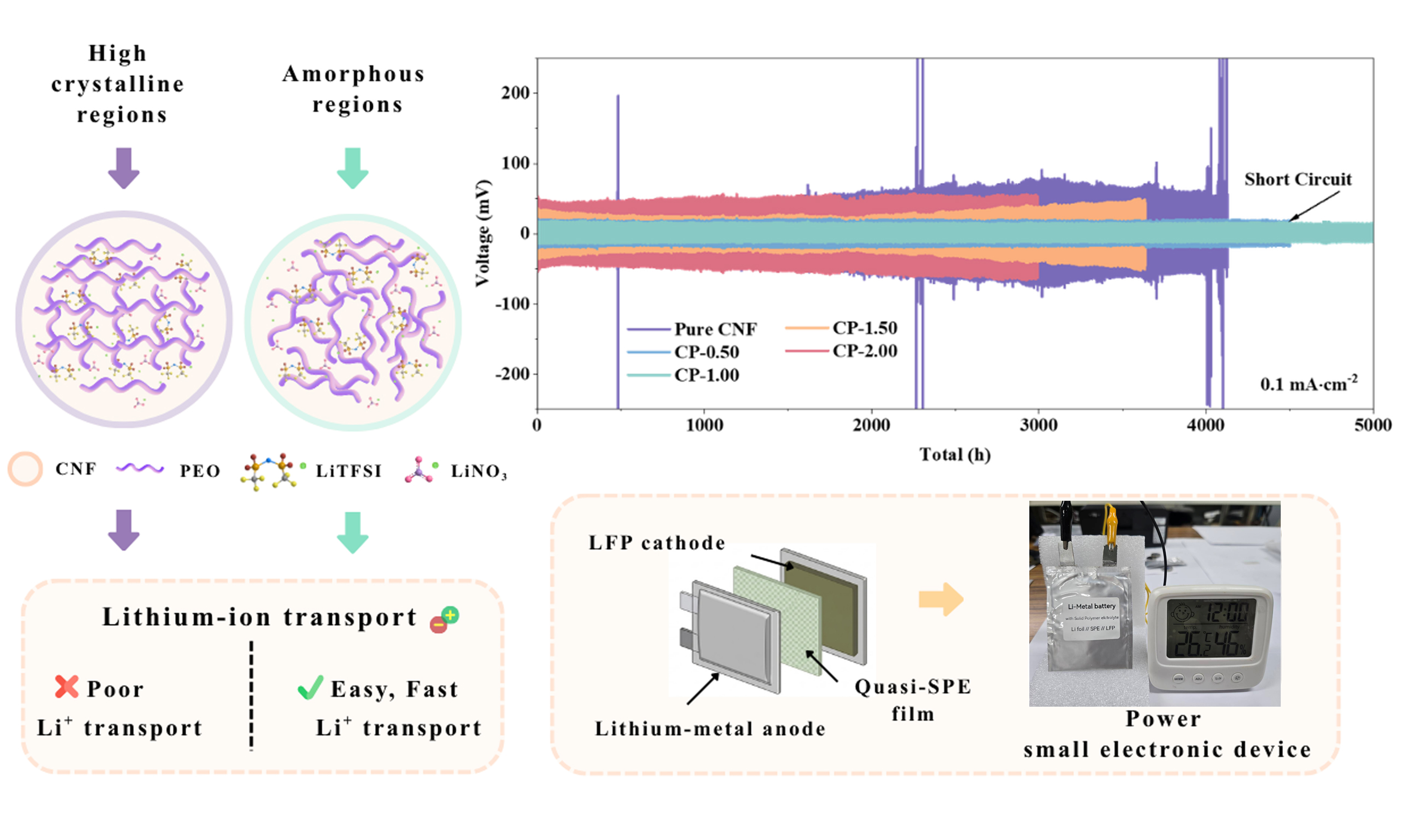
Solid-state lithium-metal batteries are promising next-generation energy storage systems owing to their high energy density and enhanced safety. However, conventional polyethylene oxide (PEO)-based solid polymer electrolytes have low ionic conductivity at room temperature, poor Li+ transference numbers, and unstable electrode interfaces, which hinder their practical deployment. Herein, we report quasi-solid polymer electrolyte (quasi-SPE) films prepared by blending cellulose nanofiber (CNF) with PEO in various ratios (0.50:0-0.50:2.0), incorporating 1 M Lithium bis(trifluoromethane)sulfonimide (LiTFSI) in 1,3-Dioxolane (DOL):1,2-Dimethoxyethane (DME) (1:1 vol%) with 1 wt.% LiNO3. Structural analyses [X-ray diffraction (XRD), scanning electron microscopy (SEM), differential scanning calorimetry (DSC), Fourier-transform infrared (FT-IR) spectroscopy, and Raman spectroscopy] revealed that moderate PEO incorporation disrupted CNF crystallinity and generated amorphous domains that enhanced polymer chain mobility and Li-ion transport, whereas excessive PEO promoted recrystallization. Within the composition range of 0.50-1.50, ionic conductivity reached ~10-4 S·cm-1 at room temperature. Notably, CP-1.00 emerged as the balanced formulation for lithium-metal battery applications, achieving a Li+ transference number of 0.46 and a wide electrochemical stability window of 4.68 V vs. Li+/Li. Symmetric Li||CP-1.00||Li cells exhibited exceptional interfacial stability, sustaining plating/stripping of around 10,000 h at 0.1 mA·cm-2 with a low overpotential of 34.0 mV. In Li||CP-1.00||Lithium iron phosphate (LFP) full cells, CP-1.00 delivered 169.2 mAh·g-1 at 0.1 A·g-1 with 91.46% capacity retention after 1,500 cycles. These findings establish CNF/PEO quasi-SPEs as scalable, high-performance electrolytes that overcome the limitations of conventional solid polymer electrolytes, thereby offering a promising pathway toward safe and durable lithium-metal batteries.
Keywords


 Download PDF
INTRODUCTION
In recent years, high-performance lithium-ion batteries (LIBs) have seen substantial demand owing to their widespread applications in energy storage, electric vehicles, and portable electronic devices[1-2]. A typical commercial LIB comprises an organic liquid electrolyte, a graphite anode, and a transition-metal oxide cathode. Although liquid electrolytes exhibit high ionic conductivity, they have drawbacks such as undesirable side reactions, leakage, flammability, and volatility, which reduce battery lifespan and degrade safety, particularly under extreme operating conditions[2-3].
By contrast, solid-state batteries use solid electrolytes, unlike conventional LIBs[4-6]. These electrolytes can be prepared using ceramics or polymers[7-9]. Solid-state batteries are considered safer and more efficient because they reduce the electrolyte leakage, flammability, and thermal instability risks associated with conventional liquid electrolytes[10,11], especially when paired with high-capacity electrodes such as lithium metal, which has a theoretical specific capacity of ~3,860 mAh·g-1[8].
Conventional solid electrolytes are often characterized by low ionic conductivity, limited mechanical flexibility, and difficulty forming stable interfaces with electrodes, which collectively reduce battery efficiency. Their inability to maintain adequate ionic mobility and interfacial stability induces capacity fading, degrades cycling performance, and limits rate capability, thereby restricting their use in real-world high-performance batteries[12]. As an alternative, cellulose nanofiber (CNF) has advantages such as mechanical strength, biodegradability, and thermal stability. However, its intrinsic ionic conductivity and flexibility are insufficient for effective electrolyte performance. Meanwhile, polyethylene oxide (PEO)-based electrolytes[8,13] are known for their low interfacial resistance, good electrode compatibility, flexibility, ease of processing, and relatively low manufacturing cost. However, at room temperature, PEO-based solid polymer electrolytes exhibit insufficient ionic conductivity (< 10-6 S·cm-1) and low Li+ transference numbers (0.10-0.30), falling short compared to liquid electrolytes[14,15]. These limitations have prompted researchers to adopt diverse strategies for enhancing the performance of solid electrolytes.
Among solid electrolytes, PEO-based solid polymer electrolytes have been studied extensively owing to their flexibility, good electrode compatibility, and ability to dissolve lithium salts through coordination between ether oxygen groups and Li+ ions[16]. This composite electrolyte achieved an ionic conductivity of
Recently, quasi-solid polymer electrolytes (quasi-SPEs), which combine the advantages of solid polymer matrices with improved electrolyte retention and reduced leakage compared to conventional liquid electrolyte systems, have emerged as a promising alternative[19]. Despite these benefits, their practical application remains limited because of challenges such as low ionic conductivity at room temperature, limited Li+ transference numbers, and poor stability under high-voltage operation[20,21]. Moreover, the influence of CNF/PEO composition on the balance between the crystalline and amorphous phases remains insufficiently understood.
In this study, quasi-SPE films were developed by combining a CNF matrix with PEO. By optimizing the CNF:PEO ratio, the films achieve a balance between crystalline and amorphous regions, which enhances their ionic conductivity, facilitates efficient Li+ transport, and improves cycling stability. This balance is critical for advancing high-performance battery applications and overcoming the inherent limitations of conventional electrolytes. The resulting quasi-SPE films exhibit improved ionic conductivity, mechanical flexibility, and electrochemical stability, positioning them as promising candidates for next-generation lithium-ion batteries.
EXPERIMENTAL
Preparation of quasi-solid polymer electrolyte films
Figure 1 schematically depicts the preparation of quasi-SPE films by combining 20 g of 2.5 wt.% CNF solution with PEO in CNF:PEO mass ratios of 0.50:0, 0.50:0.50, 0.50:1.00, 0.50:1.50, and 0.50:2.00 [Supplementary Table 1]. The mixtures were first dissolved in 80 mL of distilled water, heated to 100 °C, and stirred for 3 h to ensure complete dissolution and uniform mixing. The resulting solution was filtered under reduced pressure to remove excess liquid and trapped air bubbles. The slurry was cast into a Teflon tray to form an even layer and dried in an oven to eliminate residual moisture, yielding solid CNF/PEO hybrid films. Finally, 10-µL droplets of 1 M LiTFSI in 1,3-Dioxolane (DOL):1,2-Dimethoxyethane (DME)
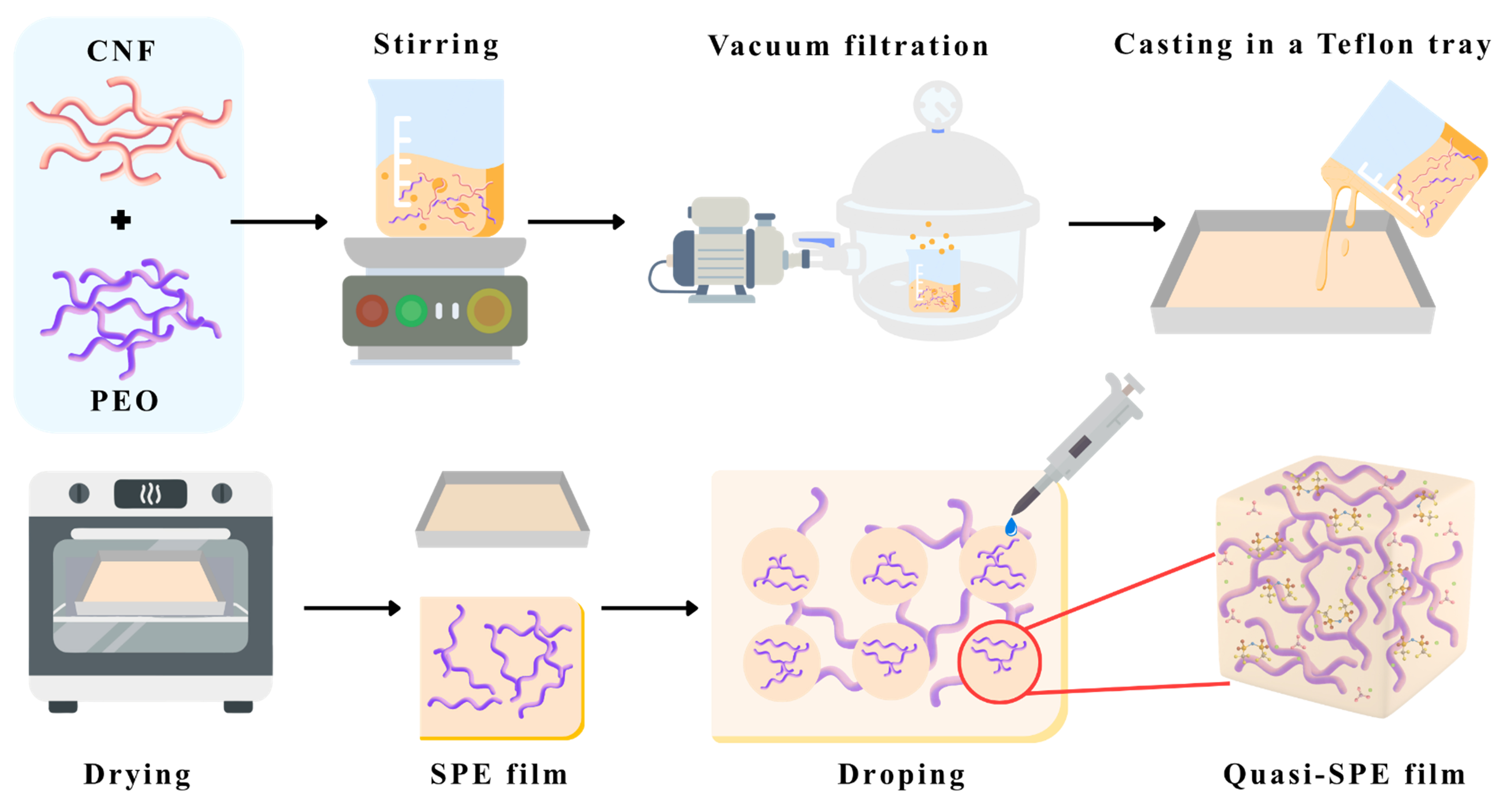
Figure 1. Schematic diagram of quasi-solid polymer electrolyte (quasi-SPE) films. CNF: Cellulose nanofiber; PEO: polyethylene oxide.
Material characterization
The quasi-SPE films were characterized with various analytical techniques to examine their structure, composition, and properties. X-ray diffraction (XRD, Bruker D8 Advance, Cu-Kα radiation, 2θ = 5° - 40°) was performed to analyze the crystal structures of the prepared materials. The morphology and microstructure of these materials were examined using field emission scanning electron microscopy (FE-SEM, JEOL JSM-IT800IS). Differential scanning calorimetry (DSC) analysis of the quasi-SPE films was performed using a Netzsch DSC 3500 Sirius to measure their thermal behavior. The 4-5 mg samples were heated from 30 °C to 120 °C at a rate of 10 °C/min. Raman spectroscopy analysis of the developed films, including investigation of their chemical composition, molecular vibrations, and structural properties, was performed using the Horiba XploRA-PLUS Confocal Raman Microscope from AIST-NT Inc. The samples were scanned using a 785 nm laser at 50% intensity, and for measurements, a 50x objective lens was used. Additionally, Fourier-transform infrared spectroscopy (FT-IR, Thermo Scientific Nicolet iS10 Infrared Microscope) was performed in the attenuated total reflectance (ATR) mode over a wavenumber range of 4,000-500 cm-1 to identify functional groups and chemical bonds within the materials.
Preparation of cathodes and fabrication of coin cell-type lithium-metal batteries
The cathodes for the lithium-metal batteries were prepared by mixing the active material (LiFePO4, LFP), conductive acetylene black, and 10 wt.% of Polyvinylidene fluoride (PVDF) in N-methyl-2-pyrrolidone (NMP) solvent at a mass ratio of 8:1:1. The mixture was stirred for 3 h to form a homogeneous slurry. This slurry was coated onto carbon-coated Al foil using a doctor-blade coater and dried at 80 °C for 3 h in an air oven. Thereafter, the electrode was placed in a vacuum oven and dried overnight at 80 °C under vacuum to ensure complete solvent removal. The final electrode was cut into discs measuring 14 mm in diameter, and the average mass loading of the active material was approximately 2.5 mg per cm-2.
The electrochemical performance of the quasi-SPE films was evaluated by fabricating a CR2032 coin cell with a lithium-metal foil measuring 16 mm in diameter. The prepared Pure CNF, CP-0.50, CP-1.00, CP-1.50, and CP-2.00 films were cut into discs measuring 19 mm in diameter and used as the electrolyte.
Electrochemical measurements
A galvanostatic charge/discharge (GCD) test was carried out to evaluate the rate capability and long-term cycling stability of the prepared materials within an assembled CR2032-type coin cell in an argon-filled glovebox with O2 and H2O content lower than 0.1 ppm. These cells were tested using a battery tester (BTS-4000, NEWARE, China) with an operating range of 2.0-4.2 V at 25 °C in battery test chambers. Electrochemical impedance spectroscopy (EIS) measurements were performed using the fabricated quasi-SPE films sandwiched between two stainless-steel sheets over a frequency range of 0.01 Hz to 100 kHz. The ionic conductivity of the prepared materials was initially calculated at 25 °C. Temperature-dependent EIS measurements were subsequently conducted at 25, 40, and 60 °C for Arrhenius analysis. The cells were placed in a temperature-controlled chamber and heated stepwise from 25 to 40 and 60 °C. The samples were allowed to equilibrate for 60 min at each temperature before each measurement to ensure thermal stabilization. Symmetric Li||quasi-SPE films||Li cells were assembled to determine their lithium-ion transference number by means of alternating current (AC) impedance spectroscopy before and after polarization. These impedance measurements were performed over a frequency range of 0.01 Hz-100 kHz, and tLi+ was calculated accordingly. Linear sweep voltammetry (LSV) was performed at a scan rate of
RESULTS AND DISCUSSION
Morphological characterization
Figure 2A depicts optical photographs of the quasi-SPE films after the application of 1 M LiTFSI in DOL:DME (1:1 vol%) with 1 wt.% LiNO3. Slight appearance variations are observed depending on PEO composition; Figure 2B presents their XRD patterns, highlighting changes in crystallinity with increasing PEO content. Pure CNF exhibits peaks at 2θ values of approximately 16.5° and 26° (JCPDS: 50-2241), indicative of its crystalline nature[22]. Upon PEO incorporation, new peaks emerge at 2θ ~ 19° and 23°, reflecting CNF-PEO interactions. After PEO incorporation (CP-0.50 to CP-2.00), the cellulose diffraction intensity decreases, and new diffraction features associated with crystalline PEO appear at around 19° and 23°, confirming the coexistence of CNF and PEO phases (JCPDS: 53-1861)[23-25]. At low PEO content (CP-0.50 and CP-1.00), the interaction between CNF hydroxyl groups and PEO ether oxygen atoms disrupts polymer chain ordering and increases the amorphous fraction. However, further PEO addition promotes PEO chain ordering and crystalline lamella formation, thus increasing the crystallinity of CP-1.50 and CP-2.00. The incorporation of LiTFSI with DOL:DME electrolyte leads to plasticization and Li+ coordination, which modify the crystalline and amorphous balance and influence ion transport behavior[26,27]. Figure 2C-G presents SEM images of the quasi-SPE films with applied electrolyte droplets. Pure CNF [Figure 2C] retains a dense fibrous network, but slight swelling and surface changes occur upon electrolyte addition. CP-0.50 [Figure 2D] shows a less dense fibrous network with fewer interconnections between fibers and improved integration of LiTFSI into the CNF-PEO blend, thereby enhancing ionic conductivity. CP-1.00 [Figure 2E] shows uniform CNF-PEO distribution, resulting in the formation of a homogeneous conductive network while maintaining structural integrity[26]. CP-1.50 [Figure 2F] shows more evident phase separation as PEO covers CNF regions, while CP-2.00 [Figure 2G] shows PEO agglomerates surrounding the CNF framework. Figure 2H depicts elemental mapping, confirming the presence and distribution of CNF, PEO, and electrolyte components. Carbon and oxygen dominate the CNF and PEO phases, while sulfur and fluorine (from LiTFSI) and nitrogen from LiNO3 are clearly detected. Increasing PEO content drives a morphological transition from a dense CNF network to distinct phase-separated structures with PEO agglomerates. These interactions with LiTFSI and LiNO3 enhance ionic conductivity but also alter the mechanical properties of the polymer matrix.
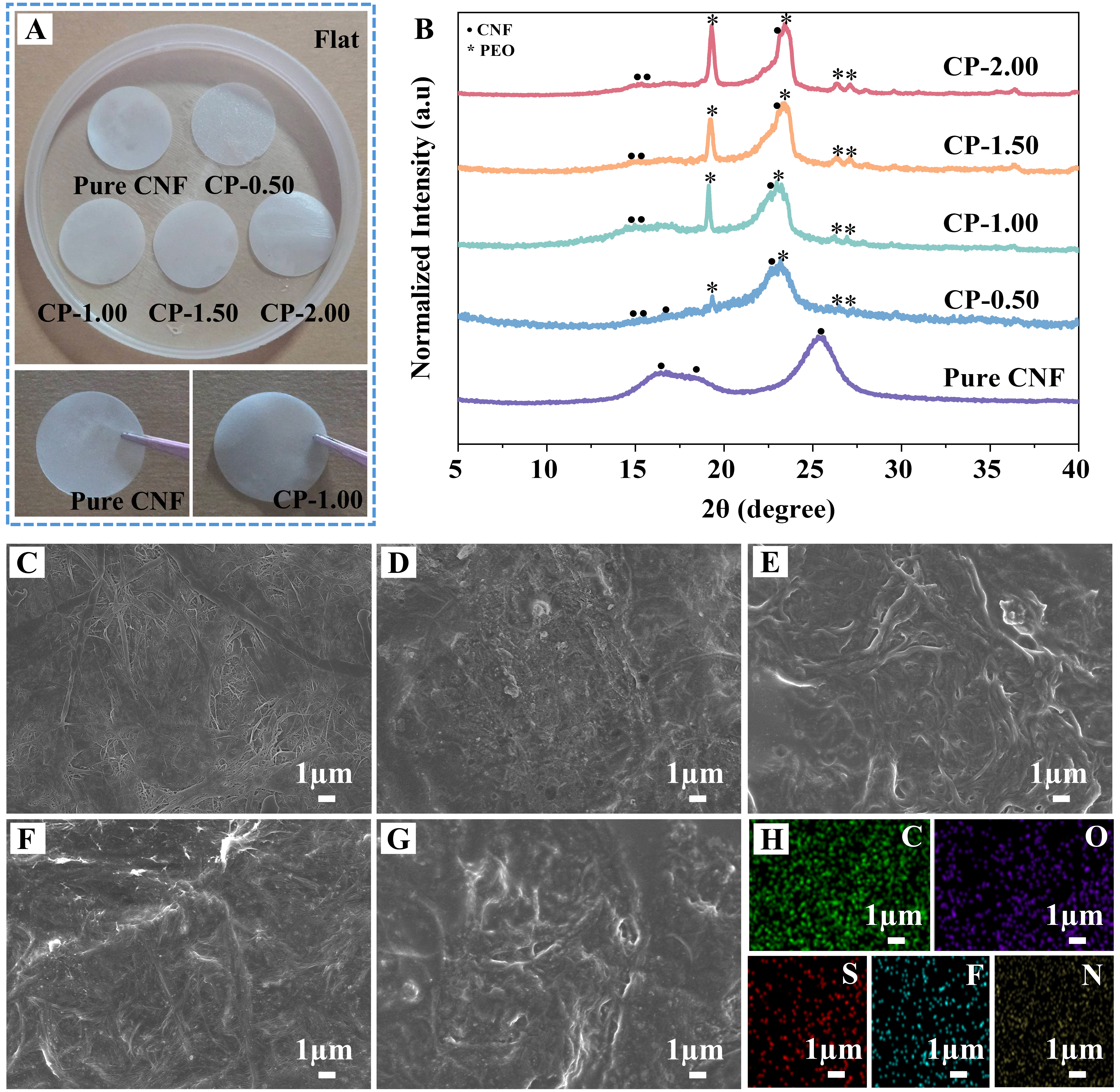
Figure 2. (A) Optical photographs of quasi-SPE films after spraying droplets of 1 M LiTFSI in DOL:DME (1:1 vol.%) + 1 wt.% LiNO3; (B) XRD patterns of quasi-SPE films; (C-G) SEM images of pure CNF, CP-0.50, CP-1.00, CP-1.50, and CP-2.00, respectively; (H) Elemental maps of C, O, S, F, and N of CP-1.00. CNF: Cellulose nanofiber; PEO: polyethylene oxide; quasi-SPE: quasi-solid polymer electrolyte; XRD: X-ray diffraction; SEM: scanning electron microscopy; LiTFSI: lithium bis(trifluoromethane)sulfonimide; DME: 1,2-dimethoxyethane; DOL: 1,3-dioxolane.
CNF incorporation into the PEO matrix induces hydrogen bonding interactions between the hydroxyl groups of CNF and the ether oxygen atoms of PEO. These interactions disturb the regular arrangement of PEO chains and suppress crystalline phase formation, thus increasing the amorphous fraction, as shown in Figure 3A. This structure with a greater amorphous fraction promotes Li+ mobility and improves the practical applicability of the composite solid polymer electrolyte. By contrast, with excessive PEO loading [Figure 3B], the increased number of PEO chains facilitates ordered chain packing around CNF surfaces, where CNF acts as a nucleation site for PEO crystallization. This increases crystalline lamellae formation, leading to higher crystallinity and reduced amorphous regions for Li+ transport.
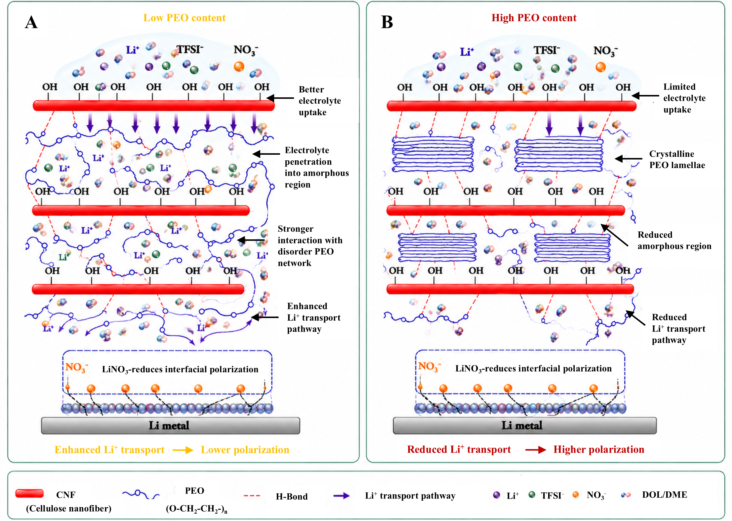
Figure 3. Schematic illustration of molecular interactions and structural evolution in CNF/PEO quasi-solid polymer electrolyte with (A) low and (B) high PEO content. CNF: Cellulose nanofiber; PEO: polyethylene oxide; LiTFSI: lithium bis(trifluoromethane)sulfonimide; DME: 1,2-dimethoxyethane; DOL: 1,3-dioxolane.
Although high PEO content improves structural integrity and may enhance mechanical stability, excessive crystallization can reduce polymer chain mobility and limit ionic transport. Moreover, the addition of LiTFSI/DOL:DME electrolyte creates competition between solvent-induced plasticization and PEO crystallization. Therefore, an optimized CNF:PEO ratio is required to maintain sufficient amorphous regions for electrolyte uptake and Li+ transport while preserving the mechanical stability provided by crystalline domains. The presence of LiNO3 further contributes to electrochemical stability by modifying the interfacial ion environment, supporting the formation of a more stable electrolyte/electrode interface. These structural changes directly influence the mechanical properties, electrolyte retention, and ionic conductivity of the quasi-SPE films.
Figure 4A schematically illustrates the quasi-SPE interface and Li-ion diffusion pathways, highlighting the relationship between physical morphology and ion transport. In highly crystalline structures, tightly packed PEO chains and CNF regions restrict polymer segment motion, thus suppressing ion mobility and reducing conductivity. By contrast, amorphous quasi-SPEs maintain disordered and flexible regions that create free volume, thus facilitating Li-ion migration through the polymer matrix. By tuning the CNF:PEO ratio and incorporating ionic liquids, the amorphous character can be preserved, which is essential for achieving high ionic conductivity in solid-state batteries. High crystallinity is undesirable because Li-ion transport relies primarily on polymer chain segment motion, which occurs only in amorphous regions[25,27]. Figure 4B shows the DSC curves of the quasi-SPE films. Pure CNF shows no distinct melting transition, which is consistent with its rigid, highly crystalline nature and lack of a glassy-to-rubbery phase transition. The flat DSC profile indicates negligible thermal changes within the tested range. By contrast, the PEO-containing samples show sharp endothermic peaks corresponding to the melting temperature (Tm) of PEO. CP-0.50 shows a peak at ~57.7 °C, reflecting a largely amorphous structure with limited chain ordering[26]. As the PEO content increases, Tm shifts upward: CP-1.00 (~63.6 °C), CP-1.50 (~64.1 °C), and CP-2.00 (~66.0 °C), indicating progressively higher crystallinity and chain alignment within the PEO matrix. These results confirm that PEO, as a semi-crystalline polymer, forms both crystalline and amorphous regions, with crystallinity increasing proportionally to PEO content[24-26].
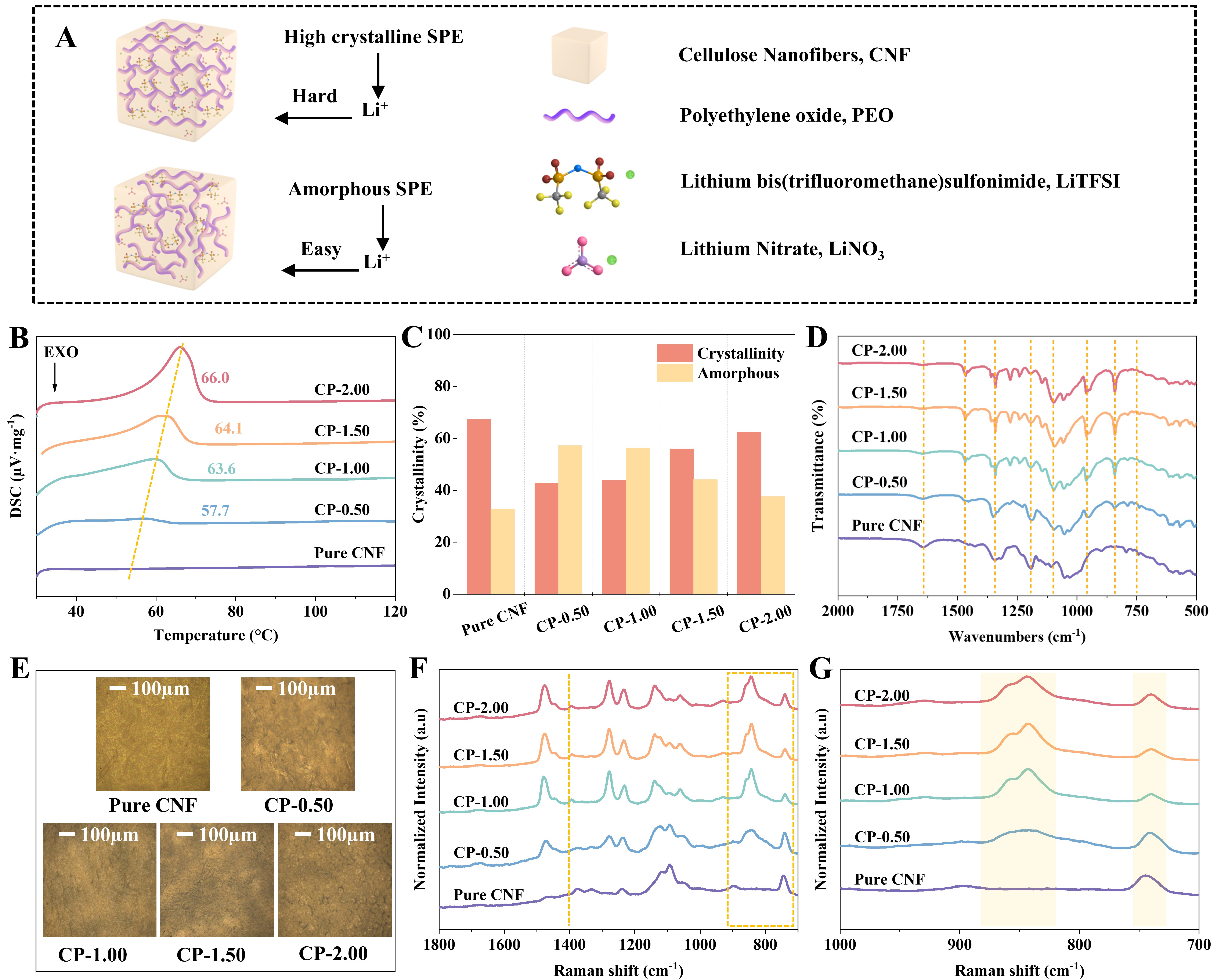
Figure 4. (A) Schematic illustration of the quasi-SPE interface and Li+ diffusion paths; (B) Differential scanning calorimetry; (C) The % crystallinity of samples; (D) FT-IR spectra; (E) Optical photographs at 10× magnification; (F-G) Raman spectra in the 1,800-700 cm-1 and 1,000-700 cm-1 regions, respectively. SPE: Solid polymer electrolyte; FT-IR: Fourier-transform infrared spectroscopy.
Figure 4C presents the percentage crystallinity data. TOPAS software was used to calculate crystalline and amorphous phases from XRD data. The results illustrate the relationship between the crystalline and amorphous phases as the CNF:PEO ratio increases. The crystallinity of CNF/PEO composites was strongly influenced by PEO concentration. Pure CNF exhibited the highest crystallinity (67.2%) because cellulose is inherently crystalline. The incorporation of a small amount of PEO (0.5-1.0 g) decreased the overall crystallinity (42.74% for CP-0.50 and 43.75% for CP-1.00) because PEO introduced additional amorphous regions and disrupted the ordered cellulose structure. However, as the PEO concentration increased to 1.5 and 2.0 g, crystallinity increased significantly to 55.9% and 62.4%, respectively. This enhancement was attributed to CNF’s ability to act as a nucleating agent and promote PEO chain ordering through hydrogen bonding interactions between hydroxyl groups of CNF and ether oxygen atoms of PEO. Consequently, additional crystalline PEO domains were formed, resulting in reduced chain mobility and a more ordered polymer structure[25]. The incorporation of LiTFSI further modified the crystalline and amorphous balance of the CNF and PEO quasi-SPE. The ether oxygen atoms of PEO interacted with Li ions through coordination, while DOL/DME molecules acted as plasticizing agents that penetrated the polymer matrix and increased local chain flexibility. At low PEO concentrations, the electrolyte preferentially penetrated a highly amorphous CNF/PEO network, thus weakening intermolecular interactions and increasing polymer segment motion. This enhanced amorphous character facilitated Li+ migration through continuous ion-conducting pathways. By contrast, at high PEO concentrations, although the electrolyte provided abundant ether oxygen sites for Li+ coordination, the presence of highly ordered crystalline PEO lamellae restricted electrolyte penetration and limited segment mobility. The coordination between Li+ and PEO oxygen atoms may have partially stabilized ordered chain conformations, while the crystalline regions acted as physical barriers to ion transport. Therefore, excessive PEO-induced crystallization reduced the fraction of ion-conducting amorphous domains despite improving mechanical integrity[27].
Figure 4D presents the FT-IR spectra of the quasi-SPE films (2,000-500 cm-1, ATR mode) and full spectra in Supplementary Figure 1, highlighting their functional groups and chemical interactions within CNF-PEO blends. As the PEO content increases (CP-0.50 to CP-2.00), the PEO peaks become sharper and more intense. The characteristic cellulose fingerprint peak at 897 cm-1 (β-glycosidic linkages) diminishes as the PEO concentration increases, while the cellulose C-O stretching peaks at 1,030 and 1,060 cm-1 overlap with the PEO ether peaks, confirming the molecular-level integration of CNF and PEO[28,29]. The broad band near 1,100 cm-1 (C-O-C stretching) represents the ether groups in the PEO backbone[30,31].
The peak at 750 cm-1 corresponds to free LiTFSI ions, while the coordination shifts in the 1,100-1,200 cm-1 region indicate Li-ion binding to PEO oxygens, which disrupts CNF hydrogen bonding[32]. The additional peaks at 1,190 and 1,350 cm-1 (SO2 stretching) confirm the presence of TFSI, while the CH2 wagging/bending peaks at 1,342 and 1,466 cm-1 serve as markers of PEO crystallinity, becoming more defined in CP-2.00. These results corroborate the XRD and % crystallinity data: CP-0.50 exhibits a blended, amorphous spectrum, whereas CP-2.00 shows sharp, distinct peaks, characteristic of a highly crystalline polymer structure[30]. Optical micrographs [Figure 4E] further illustrate these morphological changes. Pure CNF and CP-0.50 display dense fibrous surfaces with limited ionic liquid absorption. CP-1.00 appears smooth and uniform, with enhanced absorption and blending. CP-1.50 shows localized PEO aggregation, while CP-2.00 exhibits grainy, bumpy textures with crystalline clusters.
This transition from smooth to rough surfaces confirms that excessive PEO crystallization increases microscale roughness, thereby raising resistance to Li-ion transport. The electrolyte uptake capability of the prepared CNF/PEO films was evaluated by measuring their weight change before and after electrolyte incorporation, and the results are given in Supplementary Table 2. Electrolyte uptake initially increased from 53.44% (pure CNF) to a maximum of 91.92% (CP-1.00) owing to reduced crystallinity and an interconnected network. Further increasing the CP content decreased the uptake (82.37% for CP-1.50 and 75.4% for CP-2.00) because of polymer aggregation, identifying CP-1.00 as the optimal composition.
Supplementary Figure 2 shows the electrolyte retention stability of the quasi-SPE films, which was evaluated over 5-60 min at 40 °C. Pure CNF showed significant weight loss (~81.18% retention after 60 min) owing to rapid solvent evaporation. By contrast, all the quasi-SPE films exhibited superior retention (> 90.76%), with CP-1.00 reaching the highest ratio (94.71%), thus confirming that polymer incorporation effectively mitigated evaporation and enhanced solvent immobilization within the polymer network. Figure 4F and G presents Raman spectra of the quasi-SPE films, as measured using a 785-nm laser at 50% intensity with a 50× objective lens, covering the range of 1,800-700 cm-1 and zoomed in on 1,000-700 cm-1. These spectra reveal the structural changes and ion solvation behavior as PEO content increases within the CNF matrix.
Pure CNF exhibited characteristic cellulose backbone peaks, although these peaks were relatively weak compared to PEO-containing samples. As the PEO content increases (CP-0.50 to CP-2.00), sharp peaks emerge and dominate the spectra, particularly at 842 cm-1 (C-O-C stretching/CH2 rocking) and 1,475 cm-1 (CH2 bending)[33]. The growing intensity and sharpness of these peaks indicate the transition of PEO chains from amorphous to more ordered crystalline states, consistent with the XRD and crystallinity data. “The yellow highlight in Figure 4G is a zoomed region around 770-700 cm-1 [Supplementary Figure 3] is especially significant for probing salt behavior. This peak corresponds to expansion/contraction of the TFSI- anion[30,33,34]. To examine the interaction between Li+ and TFSI-, various TFSI- ion pairs were defined by bending vibration positions, as shown in Supplementary Figure 3. The peaks located at 733-738 cm-1,
Figure 5A and B shows EIS plots of the SS||quasi-SPE films||SS cells, and Figure 5C shows the equivalent circuit used to fit and obtain the bulk resistance (Rb) and ionic conductivity. The Rb obtained from EIS fitting was strongly dependent on the PEO content. PEO incorporation significantly reduced the bulk resistance from 5.37 × 10² Ω for pure CNF to 1.56 × 101 Ω for CP-0.50, thereby enhancing Li+ transport within the composite electrolyte. The reduced resistance was attributed to the ether oxygen groups of PEO, which facilitate Li+ coordination and increase ion-conducting pathways. However, excessive PEO addition in CP-2.00 increased the bulk resistance, likely because of increased PEO crystallization that restricts ion mobility. Moreover, optimized PEO content is needed to achieve low resistance and high ionic conductivity. Ionic conductivity was calculated using:
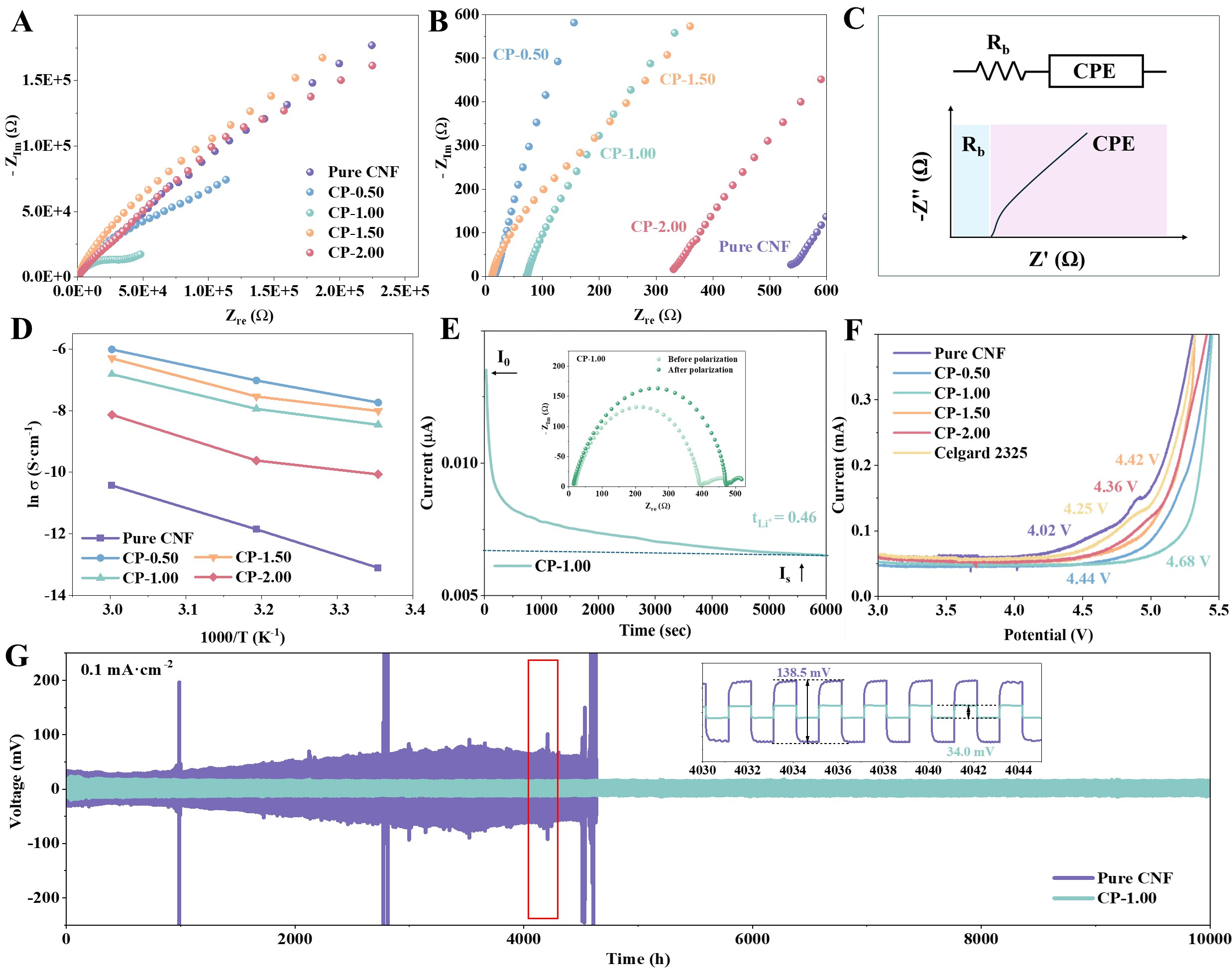
Figure 5. (A and B) EIS plots of SS||quasi-SPE films||SS cells and an enlarged view of the high-frequency region; (C) Equivalent circuit proposed to model ionic conductivity; (D) Arrhenius plots of conductivity change with quasi-SPE film temperature; (E) Chronoamperometry curves of Li||CP-1.00||Li cell, inset EIS plots of CP-1.00 before and after polarization; (F) Linear sweep voltammetry of quasi-SPE films; (G) Galvanostatic lithium stripping and plating for Li||pure CNF||Li and Li||CP-1.00||Li. CNF: Cellulose nanofiber; EIS: electrochemical impedance spectroscopy; quasi-SPE: quasi-solid polymer electrolyte; CPE: constant phase element; Rb: bulk resistance; SS: stainless steel.
where σ and L denote the ionic conductivity and thickness of the electrolyte film, respectively, while Rb is its bulk resistance obtained from EIS fitting, and A is the electrode contact area. The ionic conductivity of the quasi-SPE electrolyte films depended strongly on their PEO content. Pure CNF exhibited the lowest ionic conductivity of 10-6 S·cm-1, which was attributed to its highly crystalline cellulose structure that restricted Li+ migration. After PEO incorporation, the ionic conductivity increased significantly and reached 10-4 S·cm-1
The temperature dependence of these films’ ionic conductivity was evaluated using their Arrhenius relationship. To this end, we plotted the values given in Supplementary Table 4 against Figure 5D. All the quasi-SPE films exhibited an approximately linear relationship, indicating thermally activated ion transport behavior. The activation energy (Ea) for Li+ transport was evaluated using the Arrhenius equation:
where σ is ionic conductivity, σ0 is a pre-exponential factor, Ea is the activation energy associated with ion migration, KB is Boltzmann’s constant, and T is absolute temperature. The activation energy values were obtained from the slope of the linear fit between ln(σ) and 1000/T. The activation energy values were 0.62, 0.42, 0.45, 0.42, and 0.51 eV for Pure CNF, CP-0.50, CP-1.00, CP-1.50, and CP-2.00, respectively [Supplementary Table 5]. Pure CNF had the highest activation energy, indicating that the highly crystalline cellulose structure imposed a higher energy barrier for Li+ migration. PEO incorporation reduced the activation energy by providing oxygen sites for Li+ coordination and enhancing polymer chain mobility. CP-0.50, CP-1.00, and CP-1.50 showed low activation energy approximately 0.4 eV, suggesting more favorable Li+ transport kinetics. However, excessive PEO addition increased the activation energy of CP-2.00 to 0.51 eV, which was attributed to increased PEO crystallization and restricted ion-conducting pathways. This result suggests that an optimized PEO content facilitates Li+ coordination while maintaining sufficient amorphous pathways for ion migration.
Impedance spectroscopy tests were conducted before and after Direct Current (DC) polarization to measure impedance changes and track the effect of polarization on the ionic conductivity of the CP-1.00 quasi-SPE film. DC polarization was performed until a steady-state current was reached [Figure 5E]. The impedance spectra obtained before and after polarization show typical semicircles, which is characteristic of charge-transfer resistance (Rct). After polarization, the Nyquist plot shifts slightly, indicating changes in the electrochemical properties of the quasi-SPE film sample. The initial current (I0) was recorded at the start of polarization, and the steady-state current (Is) was noted once the current stabilized. Transference numbers were calculated using the Bruce-Vincent-Evans equation:
Here, I0 and Is denote the steady-state currents before and after polarization, representing the current when the system stabilizes. ΔV is the applied polarization voltage. R0 and Rs are the initial resistances before and after polarization, and they were calculated from the EIS results before and after DC polarization, which are 382 and 465 Ω, respectively. Initially, current (I0) increases rapidly, which is typical when a potential is applied, and the ions begin to move and form a stable electrolyte interface. After this initial current spike, the system stabilizes, and the current decreases to a steady-state value (Is), which is the steady-state current after polarization. At room temperature, the transference number for CP-1.00 was 0.46, which was higher than that for pure CNF. This indicates that the CP-1.00 electrolyte transports lithium ions more efficiently than Pure CNF because the amorphous structure of CP-1.00 facilitates better Li-ion diffusion and higher ionic conductivity, whereas pure CNF shows less efficient ion transport, higher crystallinity, and lower conductivity[36].
The electrochemical window stability of the quasi-SPE electrolyte films was evaluated with LSV by assembling Li||quasi-SPE film|| stainless steel cells and observing their stability from 3.00 to 5.50 V vs. Li+/Li at a scan rate of 1.0 mV·s-1. The results in Figure 5F indicate that the electrochemical stability of the quasi-SPE films improved after blending PEO into the cellulose nanofibers. Pure CNF shows the lowest stability, with the current rising sharply at 4.02 V, indicating electrolyte breakdown. As the PEO content increases, the onset of current rise shifts to higher voltages: 4.44 V for CP-0.50, 4.68 V for CP-1.00, 4.42 V for CP-1.50, and 4.36 V for CP-2.00. CP-1.00 has impressive electrochemical stability, allowing the electrolyte to remain stable up to 4.68 V. This is attributed to the optimized balance between PEO chain coordination with Li+ ions, CNF-induced structural reinforcement, and a sufficient amorphous phase for ion transport. Galvanostatic lithium stripping and plating measurements were performed on Li||pure CNF||Li and Li||CP-1.00 ||Li symmetric cells at a current density of 0.1 mA·cm-2 to study the electrochemical stability of the quasi-SPE films in contact with lithium-metal anodes. Figure 5G shows Li||pure CNF||Li and Li||CP-1.00||Li. CP-1.00 endured ultra-long cycles of around 10,000 h and exhibited lower overpotential than Pure CNF, indicating better stability during lithium plating and stripping. The smaller voltage changes suggest a more stable interface between the lithium anode and electrolyte, with better ionic conductivity[37]. Figure 5G as shown in the inset, the overpotential is only 34.0 mV, indicating more stable behavior during the plating and stripping cycles. By contrast, pure CNF sustained shorter cycles and underwent significantly higher voltage fluctuations during plating and stripping, indicating unstable electrochemical behavior. The large voltage spikes suggested issues with stability during lithium plating and stripping, such as dendrite formation or poor contact between the lithium metal and the quasi-SPE film[37]. As shown in the zoomed-in inset, the voltage reached 138.5 mV, which is relatively large and indicates poor cycling stability and high resistance to lithium-ion movement in the electrolyte [Supplementary Figure 4]. The smaller overpotential of CP-1.00 indicated superior performance as its amorphous structure was able to promote ion movement within the material, enhance ionic conductivity, and reduce resistance[26]. Thus, the CNF and PEO blend enhanced the stability of the electrolyte interface.
A comparison of the results of all the quasi-SPE samples is presented in Supplementary Figure 5. Li plating/stripping stability was evaluated in Li||quasi-SPE||Li symmetric cells at various current densities from 0.1 to 5 mA·cm-2. CP-1.00 exhibited improved stability compared to pure CNF, indicating enhanced Li+ transport and interfacial compatibility. The results are presented in Supplementary Figure 6.
Figure 6A shows the rate capability of the Li||quasi-SPE||LFP cathode at the current density of 0.1-2 A·g-1. All quasi-SPE films demonstrate a higher rate capability than the pure CNF film. Especially, CP-1.00 has the highest discharge specific capacity of 169.2, 158.4, 149.8, 143.3, 138.1, 123.5, 110.7, and 145.6 mAh·g-1 at 0.1, 0.2, 0.3, 0.4, 0.5, 1.0, 2.0, and 0.3 A·g-1, respectively. Clearly, the galvanostatic charge and discharge voltage profiles of Li||CP-1.00||LFP, illustrated in Figure 6B, correspond to the battery’s behavior at different current densities (i.e., 0.1, 0.2, 0.3, 0.4, 0.5, 1, and 2 A·g-1). At a low current density (0.1 A·g-1), the voltage profile is relatively flat, indicating good reversibility and stability of the Li||CP-1.00||LFP cell. It remains almost unchanged as the number of cycles increases and shows a more pronounced charge/discharge plateau. This suggests efficient lithium-ion intercalation and deintercalation with low polarization. However, as the current density increases (from 0.1 to 2 A·g-1), the voltage profiles show increased polarization, and the voltage difference between charge and discharge becomes more pronounced. This is because higher current densities demand faster ion movement, which can increase resistance, leading to poor ionic conductivity, a low Li-ion transference number, and, consequently, fading capacity[15,26]. As shown in Figure 6C, CP-1.00 delivers the most stable cycling performance, with a discharge capacity of 169.2 mAh·g-1 at 0.1 A·g-1 and a capacity retention of 91.46% over 1,500 cycles. Moreover, the galvanostatic charge and discharge voltage profiles of Li||CP-1.00||LFP, as shown in Supplementary Figure 7, correspond to the battery’s behavior. All quasi-SPE films show higher discharge capacity and capacity retention than pure CNF. Pure CNF exhibits a discharge capacity of 105.6 mAh·g-1 and capacity retention of 64.83%, which indicates poor cycling performance and low capacity due to sluggish Li-ion movement within the crystalline region and low ionic conductivity. Even at a current density of 1.0 A·g-1 [Supplementary Figure 8], CP-1.00 has remarkable long-term cycling stability, delivering a discharge capacity of 133.7 mAh·g-1 and retaining 66.35% of its capacity over 2,500 cycles. This outstanding performance demonstrates that the optimized CNF/PEO electrolyte framework sustains stable Li+ transport pathways and a robust electrode-electrolyte interface during high-rate cycling. The enhanced stability is attributed to the well-balanced crystalline-amorphous structure of CP-1.00, which promotes efficient ion migration while preserving structural integrity over prolonged operation.
Figure 6. (A) Rate capability of the Li||quasi-SPE||LFP cathode; (B) Galvanostatic charge and discharge voltage profiles of Li||CP-1.00||LFP; (C) Cycling performance of the quasi-SPE at 0.1 A·g-1; (D) Cycling performance of Li||pure CNF||LFP and Li||CP-1.00||LFP pouch cell; (E) Digital photographs of Li||CP-1.00||LFP coin cell batteries powering various devices. CNF: Cellulose nanofiber; quasi-SPE: quasi-solid polymer electrolyte; LFP: lithium iron phosphate.
Furthermore, the electrochemical performance of CP-1.00 was compared to that of a commercial Celgard 2325 separator, and the results are shown in Supplementary Figure 9. According to Figure 6D, Li||pure CNF||LFP and Li||CP-1.00||LFP pouch cells were fabricated to further assess the potential for scalable application of the quasi-SPE. These show the long-term cycling performance and deliver a high discharge capacity of ~145 mAh·g-1 over 200 cycles at 0.1 A·g-1. The galvanostatic charge and discharge voltage profiles of Li||CP-1.00||LFP, as shown in Supplementary Figure 10, correspond to the battery’s behavior during cycles 1, 50, 100, 150, and 200. Figure 6E depicts digital photographs of a Li|| CP-1.00 ||LFP coin cell battery, which powers a sensor device and small portable electronic devices, and Li||CP-1.00||LFP pouch cell batteries. The pouch cell battery, which uses an LFP cathode, provides an initial open-circuit voltage (OCV) of 3.32-3.45 V [Supplementary Figure 11]. After full charging, it reliably powers a light lamp. Pouch cell batteries are flexible, lightweight, and can provide higher capacity than coin cell batteries, making them suitable for energy storage and large electronic devices.
The blending of PEO with CNF enhances the ionic conductivity of the quasi-SPE by improving the structure from highly crystalline in pure CNF toward a more amorphous region, a conductive pathway for Li-ion movement, and a stabilized electrolyte interface. This allows faster ion movement, especially at higher current densities, and enhances cycling stability and rate capability.
CONCLUSIONS
In this work, we successfully fabricated quasi-SPE films by blending CNF with PEO in various ratios (0.50:0 to 0.50:2.00), incorporating 1 M LiTFSI in DOL:DME (1:1 vol%) with 1 wt.% LiNO3 for lithium-metal battery applications. Structural analyses (XRD, FT-IR, Raman, DSC) revealed that appropriate PEO incorporation reduced CNF’s crystallinity and expanded amorphous domains, thereby facilitating Li-ion transport through improved chain mobility. The optimized CP-1.00 composition delivered well-balanced performance for lithium-metal battery applications. It achieved an ionic conductivity of 10-4 S·cm-1, a Li+ transference number of 0.46, and the widest electrochemical stability window of 4.68 V vs. Li+/Li. Importantly, CP-1.00 demonstrated excellent interfacial stability with a lithium metal anode, sustaining ultra-long galvanostatic stripping and plating of around 10,000 h at 0.1 mA·cm-2 with a remarkably low overpotential of 34.0 mV. By contrast, pure CNF exhibited severe voltage fluctuations and a considerably higher overpotential of
DECLARATIONS
Authors’ contributions
Conceived the research, writing of the manuscript: Lolupiman, K.; Qin, J.
Methodology, data records, and analysis: Lolupiman, K.; Pattananuwat, P.; Okhawilai, M.; Zhao, F.; Qin, J.
Supervision, review, and editing, technical support and funding management: Qin, J.; Zhao, F.
All authors discussed the results and commented on the manuscript.
Availability of data and materials
The data supporting the findings of this study are available from the corresponding author upon reasonable request. Some data are not publicly available because the related intellectual property has been submitted for patent protection through the Chulalongkorn University Intellectual Property (CUIP) system.
AI and AI-assisted tools statement
During the preparation of this manuscript, the AI tools ChatGPT (version GPT-6, OpenAI, released 2026-10-07) and Grammarly (version 14.1338.0, Grammarly Inc., AI-assisted writing and grammar-checking tool, released 2026-10-14) were used for language editing, grammar checking, and proofreading. In addition, ChatGPT image generation (version GPT-5.6 Sol, OpenAI, released 2026-08-06) was used to assist in creating schematic illustrations for Figure 3A and B. The authors reviewed, modified, and integrated the AI-generated elements to accurately represent the concepts described in the manuscript. These figures do not contain experimental data generated by AI. These tools did not influence the study design, data collection, analysis, interpretation, or the scientific content of the work. All authors take full responsibility for the accuracy, integrity, and final content of the manuscript.
Financial support and sponsorship
Lolupiman, K. would like to thank The Second Century Fund (C2F), Chulalongkorn University, and the 90th Anniversary of Chulalongkorn University Scholarship under the Ratchadapisek Somphot Endowment Fund for the scholarship and research practice in the UK. This research has received funding support from the National Science, Research and Innovation Fund (NSRF) via the Research and Innovation Acceleration Agency for Competitiveness and Area Development (RCAD) (Program Management Unit for Frontier Brainpower and Future Industries, grant number B42G690095) and the Thailand Science Research and Innovation Fund Chulalongkorn University (INDFF691442300035).
Conflicts of interest
All authors declared that there are no conflicts of interest.
Ethical approval and consent to participate
Not applicable.
Consent for publication
Not applicable.
Copyright
© The Author(s) 2026.
Supplementary Materials
REFERENCES
1. Pandya, R.; Mathieson, A.; Boruah, B. D.; de Aguiar, H. B.; de Volder, M. Interrogating the light-induced charging mechanism in Li-ion batteries using operando optical microscopy. Nano. Lett. 2023, 23, 7288-96.
2. Tarascon, J. M.; Armand, M. Issues and challenges facing rechargeable lithium batteries. Nature 2001, 414, 359-67.
4. Zhao, Q.; Stalin, S.; Zhao, C.; Archer, L. A. Designing solid-state electrolytes for safe, energy-dense batteries. Nat. Rev. Mater. 2020, 5, 229-52.
5. Xia, S.; Wu, X.; Zhang, Z.; Cui, Y.; Liu, W. Practical challenges and future perspectives of all-solid-state lithium-metal batteries. Chem 2019, 5, 753-85.
6. Yu, X.; Manthiram, A. Electrode-electrolyte interfaces in lithium-based batteries. Energy. Environ. Sci. 2018, 11, 527-43.
7. Jiang, B.; Liu, Z.; Chen, H.; et al. Ceramic-in-polymer composite solid electrolyte enabled by metal-sulfur interactions with enhanced Li-ion conductivity. ACS. Appl. Energy. Mater. 2025, 8, 11884-95.
8. Chen, S.; Wen, K.; Fan, J.; Bando, Y.; Golberg, D. Progress and future prospects of high-voltage and high-safety electrolytes in advanced lithium batteries: from liquid to solid electrolytes. J. Mater. Chem. A. 2018, 6, 11631-63.
9. Wang, C.; Huang, D.; Li, S.; et al. Three-dimensional-percolated ceramic nanoparticles along natural-cellulose-derived hierarchical networks for high Li+ conductivity and mechanical strength. Nano. Lett. 2020, 20, 7397-404.
10. Jiang, W.; Wang, S.; Wang, Y.; Hu, J.; Yang, D.; Zhang, W. Silica-modified 3D porous copper current collectors toward stable lithium metal anodes. Energy. Technol. 2023, 11, 2300053.
11. Jiang, W.; Qiu, G.; Wu, D.; et al. Superlithiophilic Ag particles embedded in flexible polymer solid electrolyte interface films for dendrite-free lithium metal anodes. ACS. Sustainable. Chem. Eng. 2023, 11, 13508-18.
12. Wu, Y.; Li, Y.; Wang, Y.; Liu, Q.; Chen, Q.; Chen, M. Advances and prospects of PVDF based polymer electrolytes. J. Energy. Chem. 2022, 64, 62-84.
13. Chattopadhyay, J.; Pathak, T. S.; Santos, D. M. F. Applications of polymer electrolytes in lithium-ion batteries: a review. Polymers 2023, 15, 3907.
14. Yu, X.; Liu, Y.; Goodenough, J. B.; Manthiram, A. Rationally Designed PEGDA-LLZTO composite electrolyte for solid-state lithium batteries. ACS. Appl. Mater. Interfaces. 2021, 13, 30703-11.
15. Ishfaq, H. A.; Cruz Cardona, C.; Tchernychova, E.; et al. Transport number determination and relevance for lithium metal batteries using localized highly concentrated electrolytes. Chem. Mater. 2025, 37, 2485-95.
16. Liu, J.; Chen, Y.; Zhou, Z.; et al. Multifunctional polar polymer boosting PEO electrolytes toward high room temperature ionic conductivity, high-voltage stability, and excellent elongation. ACS. Appl. Mater. Interfaces. 2025, 17, 7821-9.
17. Yang, Z.; Cai, J.; Shen, Z.; et al. Effect of LiTFSI solvation on ionic conductivity of polyester-based solid electrolytes. Macromolecules 2024, 57, 4460-70.
18. Sundari, C. D. D.; Karunawan, J.; Santosa, S. P.; Arcana, I. M.; Iskandar, F. Role of LiTFSI salt content and salt crystallization on carboxymethyl chitosan-based solid polymer electrolytes for stable Li metal batteries. ACS. Appl. Polym. Mater. 2023, 5, 6817-27.
19. Boaretto, N.; Garcia-Calvo, O.; Cobos, M.; et al. Quasi-solid polymer electrolytes with binary and ternary salt mixtures for high-voltage lithium metal batteries. Energy. Mater. 2025, 5, 500040.
20. Jeon, N.; Jo, S.; Kim, S.; Park, M.; Kim, D. Quasi-solid-state polymer electrolytes based on a polymeric ionic liquid with high ionic conductivity and enhanced stability. J. Electrochem. Sci. Technol. 2017, 8, 257-64.
21. Lin, W.; Zheng, X.; Ma, S.; Ji, K.; Wang, C.; Chen, M. Quasi-solid polymer electrolyte with multiple lithium-ion transport pathways by in situ thermal-initiating polymerization. ACS. Appl. Mater. Interfaces. 2023, 15, 8128-37.
22. Kim, H.; Mattinen, U.; Guccini, V.; et al. Feasibility of chemically modified cellulose nanofiber membranes as lithium-ion battery separators. ACS. Appl. Mater. Interfaces. 2020, 12, 41211-22.
23. Ram, S. C. V.; Deo, S.; Zhan, P.; Janik, M. J.; Maranas, J. K. High molecular weight crystalline PEO6 -based polymer electrolytes for lithium-ion conduction-effect of cellulose nanowhiskers. J. Polym. Sci. 2024, 62, 2288-300.
24. Ma, Q.; Qi, X.; Tong, B.; et al. Novel Li[(CF3SO2)(n-C4F9SO2)N]-based polymer electrolytes for solid-state lithium batteries with superior electrochemical performance. ACS. Appl. Mater. Interfaces. 2016, 8, 29705-12.
25. Fukuya, M. N.; Senoo, K.; Kotera, M.; Yoshimoto, M.; Sakata, O. Change in the crystallite orientation of poly(ethylene oxide)/cellulose nanofiber composite films. Biomacromolecules 2017, 18, 4411-5.
26. Grundy, L. S.; Fu, S.; Hoffman, Z. J.; Balsara, N. P. Electrochemical characterization of PEO/LiTFSI electrolytes near the solubility limit. Macromolecules 2022, 55, 9030-8.
27. Bertoli, L.; Gabriele, G.; Gibertini, E.; Magagnin, L. Unconventional PEO-PPC quasi-solid state blend polymer electrolyte for high efficiency solid-state Li-metal batteries. J. Energy. Storage. 2024, 81, 110456.
28. Vârban, R.; Crișan, I.; Vârban, D.; et al. Comparative FT-IR prospecting for cellulose in stems of some fiber plants: flax, velvet leaf, hemp and jute. Appl. Sci. 2021, 11, 8570.
29. Chen, W.; He, H.; Zhu, H.; Cheng, M.; Li, Y.; Wang, S. Thermo-responsive cellulose-based material with switchable wettability for controllable oil/water separation. Polymers 2018, 10, 592.
30. Loaiza, L. C.; Johansson, P. Li-salt doped single-ion conducting polymer electrolytes for lithium battery application. Macromol. Chem. Phys. 2022, 223, 2100419.
31. Stern, T. Deciphering the triple-peak C-O-C stretching FTIR absorbance consistently occurring in semicrystalline PEG. Polymers 2025, 17, 2199.
32. Yang, S.; Zhao, M.; He, R.; et al. Solution Blow Spinning of the Benzimidazole-Containing Aramid Nanofibers for Separators of Lithium-Ion Batteries. ACS. Appl. Mater. Interfaces. 2024, 16, 15362-71.
33. Hoffman, Z. J.; Galluzzo, M. D.; Gordon, M. P.; Urban, J. J.; Balsara, N. P. Comparing theoretical salt concentration profiles in a polymer electrolyte with experimental measurements using operando Raman spectroscopy. J. Electrochem. Soc. 2023, 170, 090517.
34. Li, S.; Chen, B.; Shi, Z.; Tong, Q.; Weng, J. Optimizing strategies for high Li+ transference number in solid state electrolytes for lithium batteries: a review. J. Energy. Storage. 2024, 102, 114210.
35. Zhang, Y.; Lu, W.; Cong, L.; et al. Cross-linking network based on poly(ethylene oxide): solid polymer electrolyte for room temperature lithium battery. J. Power. Sources. 2019, 420, 63-72.
36. Wei, Z.; Chen, S.; Wang, J.; et al. Superior lithium ion conduction of polymer electrolyte with comb-like structure via solvent-free copolymerization for bipolar all-solid-state lithium battery. J. Mater. Chem. A. 2018, 6, 13438-47.
Cite This Article
 Open Access
How to Cite
Lolupiman, K.; Pattananuwat, P.; Okhawilai, M.; Zhao, F.; Qin, J. Tunable crystallinity in cellulose nanofiber-polyethylene oxide electrolyte films for stable quasi-solid-state lithium-metal batteries. Energy Mater. 2026, 6, 600154. https://dx.doi.org/10.20517/energymater.2026.297
Download Citation
If you have the appropriate software installed, you can download article citation data to the citation manager of your choice. Simply select your manager software from the list below and click on download.
Export Citation File
Type of Import
Tips on Downloading Citation
Citation Manager File Format
Type of Import
Direct Import: When the Direct Import option is selected (the default state), a dialogue box will give you the option to Save or Open the downloaded citation data. Choosing Open will either launch your citation manager or give you a choice of applications with which to use the metadata. The Save option saves the file locally for later use.
Indirect Import: When the Indirect Import option is selected, the metadata is displayed and may be copied and pasted as needed.
About This Article
Special Topic
Copyright

Data & Comments
Data
0












Comments
Comments must be written in English. Spam, offensive content, impersonation, and private information will not be permitted. If any comment is reported and identified as inappropriate content by OAE staff, the comment will be removed without notice. If you have any queries or need any help, please contact us at [email protected].