
fig4
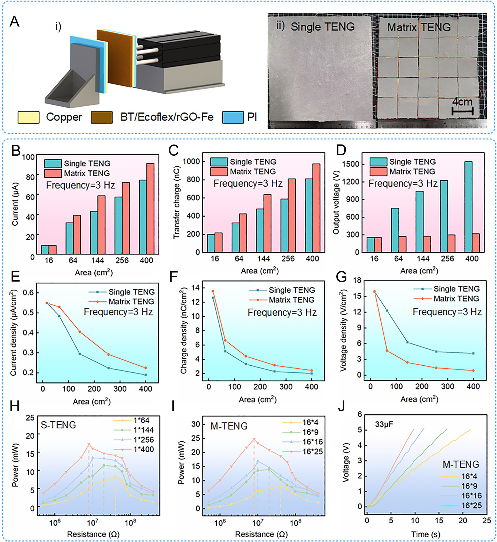
Figure 4. Comparison of electrical output performance between the S-TENG and M-TENG. (A) (i) schematic diagram of the experimental setup; (ii) integration modes of the S-TENG and M-TENG. (B) Current. (C) Transferred charge. (D) Output voltage. (E) Current density. (F) Charge density. (G) Voltage density. (H) Experimental results of matching resistance of the single TENG. (I) Experimental results of matching resistance of the matrix TENG. (J) Capacitance charging ability of the matrix TENG.