

fig6
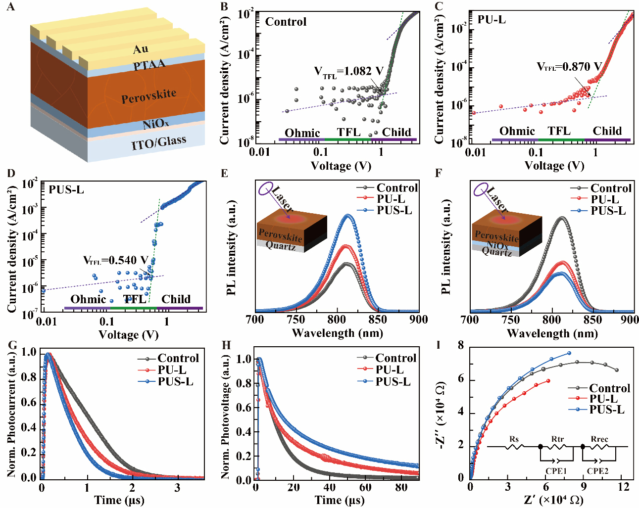
Figure 6. (A) The schematic diagram of the hole-only device. The I-V curves of (B) control, (C) PU-L, and (D) PUS-L hole-only devices. Steady-state PL spectra of the control, PU-L, and PUS-L perovskite films deposited on (E) quartz and (F) quartz/NiOx substrates; (G) TPC and (H) TPV of devices. (I) Nyquist plots of the devices, with the inset showing the equivalent circuit used for EIS fitting. TPC: Transient photocurrent; TPV: transient photovoltage; EIS: electrochemical impedance spectroscopy; PTAA: poly[bis(4-phenyl) (2,4,6-trimethylphenyl) amine]; PU-L: sample prepared using a Pb(NO3)2 precursor containing 0.3 mg/mL urea; PUS-L: the corresponding sample after additional heat treatment at 150 °C for 20 min; TFL: trap-filled limit; ITO: indium tin oxide.