


Enhancing the activity and stability of RuO2-based catalyst via nano-confinement effect for O2 evolution reaction in acid electrolyte
 0
0 Abstract
The oxygen evolution reaction (OER), as a pivotal process in electrochemical water splitting, directly determines energy conversion efficiency. Ruthenium (Ru)-based catalysts have gained considerable attention in recent years due to their decent intrinsic activity in acidic media. Previous studies have demonstrated that while Ru exhibits superior OER activity compared to RuO2 in acidic environments, its operational stability remains markedly inferior. This performance dichotomy, coupled with the persistent challenges of active species dissolution and catalyst particle aggregation during prolonged operation, significantly hinders their practical implementation in electrochemical systems. To address these challenges, this study develops a carbon nanotube (CNT)/Fe-Ni@RuO2@PANI-350 composite catalyst composed of RuO2 nanoparticles supported on bimetallic Fe-Ni modified CNTs (CNT/Fe-Ni) and encapsulated with polyaniline (PANI). This catalyst utilizes the anchoring effect of bimetallic Fe-Ni sites and the spatial confinement effect of PANI coating layer, effectively inhibiting the dissolution and agglomeration of RuO2 during both high-temperature processing and electrochemical operation, thereby significantly enhancing electrochemical stability. The anchoring strength of RuO2 nanoparticles on CNT/Fe-Ni support via the nano-confinement effect, as well as the microscopic mechanisms underlying the performance enhancement, are revealed by density functional theory calculations and experimental characterizations. The composite catalyst demonstrates fascinating OER performance in 0.5 M H2SO4, exhibiting a low Tafel slope of
Keywords
INTRODUCTION
Electrochemical water splitting is recognized as one of the most promising methods for producing H2, which is considered perhaps the ultimate sustainable and clean energy resource in modern society[1,2]. Electrochemical water splitting comprises the hydrogen evolution reaction (HER) at the cathode and the oxygen evolution reaction (OER) at the anode. Compared to HER, OER exhibits sluggish kinetics due to its complex multi-electron and proton transfer processes, making it the rate-determining step in an overall water-electrolysis process[3-5]. The high overpotentials required for OER, particularly in acidic electrolytes, and the poor stability of electrocatalysts further hinder its practical applications[6,7]. Thus, developing high-performance OER electrocatalysts in acidic environment remains challenging. In previous studies on OER catalysts, Ruthenium (Ru)-based catalysts have attracted much attention due to their relatively high activity in acidic media[8].
However, Ru-based catalysts are facing significant challenges including high cost, particle aggregation at elevated temperature during preparation, poor electrochemical stability[9-14], particularly under strong oxidizing conditions or exposed acidic electrolytes where the dissolution of Ru species leads to active site loss and rapid performance degradation[15-17]. Among these challenges, the dissolution of Ru species is directly related to stability deterioration and lifespan shortening[18].To address this challenge, previous studies have proposed various strategies, including metal doping[19], heterostructure engineering[20], defect engineering[21], morphology control[22], and modifications of catalyst supports[23]. Generally, the selection of catalyst supports plays a critical role in determining catalytic performance, as they profoundly influence the activity, stability, and electron transfer properties[24-27]. Carbon-based materials, particularly carbon nanotubes (CNTs), have emerged as prominent candidates in catalyst support research due to their exceptional electrical conductivity, large specific surface area, and superior chemical stability[28].
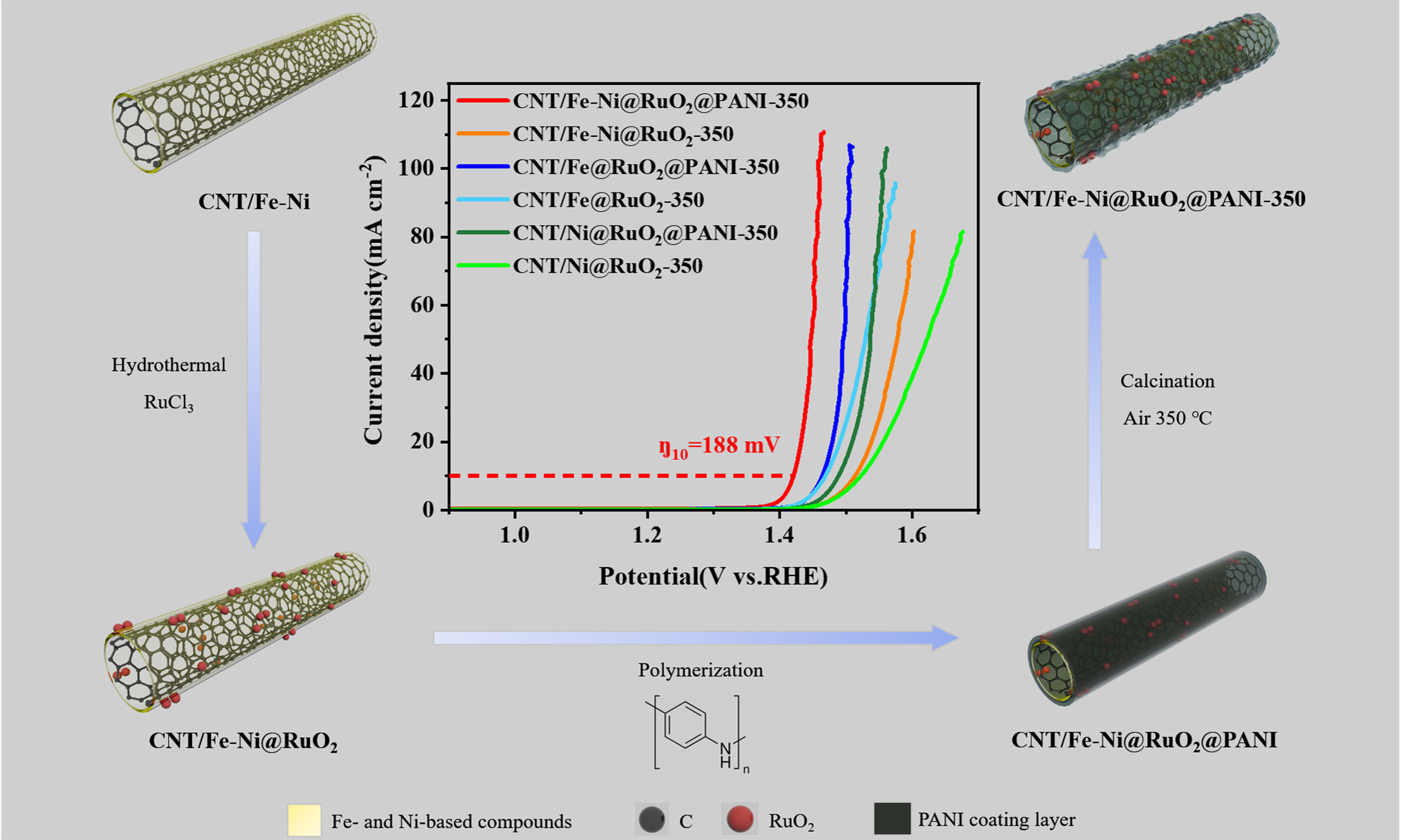
In this study, Fe-Ni co-modified CNTs (CNT/Fe-Ni) were designed as the support of Ru-based catalysts, and the catalytic activity and stability of RuO2 in OER under acidic conditions were investigated. The CNT/Fe-Ni material was synthesized via chemical vapor deposition (CVD), where ferrocene and nickelocene served not only as the catalyst for CNT growth but also as precursors to in situ form the Fe-Ni anchor sites for subsequent RuO2 growth via nano-confinement effect. Thereafter, the nanostructure is stabilized by coating with a polyaniline (PANI) layer, to prevent the agglomeration of RuO2 nanoparticles during the subsequent high-temperature treatment and electrochemical operation. Such a structure design of the composite catalyst leverages the anchoring effect of bimetallic Fe-Ni alloy to facilitate the confined growth of RuO2 nanoparticles on Fe-Ni alloy sites and establish a strong metal-support interaction. This design not only utilizes the high conductivity and large specific surface area of CNTs, but also optimizes the Ru active sites through interfacial electronic coupling between Ni, Fe, and Ru, thereby significantly enhancing the catalytic activity and stability of the catalyst during OER process. This study underscores a simple yet effective nano-confinement strategy to address challenges faced by Ru-based catalysts in acidic environments, providing a practical paradigm for designing and preparing highly efficient OER electrocatalysts with enhanced stability.
EXPERIMENTAL
Chemicals and materials
Ferrocene (high purity, ≥ 99.5%) was purchased from Alfa Aesar. Nickelocene (analytical grade, ≥ 98.0%) was obtained from Macklin. RuCl3 (analytical grade, ≥ 97.0%) was supplied by Ark Pharm. Urea (analytical grade, ≥ 99.0%) and ammonium persulfate (APS, analytical grade, ≥ 98.0%) were procured from Aladdin. Acetonitrile (analytical grade, ≥ 99.5%) was purchased from Sinopharm Chemical Reagent Co., Ltd. Aniline (analytical grade, ≥ 99.0%) was obtained from Alfa Aesar, while isopropanol (analytical grade, ≥ 99.7%) was supplied by Shanghai Lingfeng Chemical Reagent Co., Ltd. Nafion solution (5%, D520, DuPont) was purchased from Shanghai Hesen Electric Co., Ltd. All chemicals used in this work were employed without further purification.
Preparation of CNT/Fe-Ni support
A total of 50 mg of nickelocene and 50 mg of ferrocene were placed at the low-temperature zone of a tubular furnace, maintaining a constant Ar flow rate of 300 sccm inside the tube. When the furnace temperature reached 850 °C (heating rate: 4 °C min-1), an acetonitrile:ethanol mixture (v/v = 3:1) was heated to 90 °C, and the resulting vapor was introduced into the furnace using an Ar carrier gas. After 5 min of reaction, the product was cooled to obtain CNT/Fe-Ni.
Synthesis of CNT/Fe-Ni@RuO2-350
A total of 45 mg of CNT/Fe-Ni was dispersed in 42 mL of ethanol, followed by the addition of 45 mL of deionized (DI) water. The mixture was ultrasonicated for 5 min. Under continuous stirring, 3 mL of
The control samples, CNT/Ni@RuO2-350 and CNT/Fe@RuO2-350, were synthesized using 0.1 g of nickelocene and ferrocene, respectively, as catalysts for the preparation of CNT/Ni and CNT/Fe, while the subsequent steps remained unchanged.
Synthesis of CNT/Fe-Ni@RuO2@PANI-350
A total of 40 mg of CNT/Fe-Ni@RuO2 was dispersed in 40 mL of DI water via ultrasonication. The resulting mixture was placed in an ice bath, followed by the addition of 10 mL of 0.5 M HCl containing 60 μL of aniline and another 10 mL of 0.5 M HCl containing 120 mg of APS. The reaction system was continuously stirred in an ice bath for 10 h. The obtained product was washed thoroughly with water and ethanol via centrifugation and subsequently dried in an oven at 55 °C. The dried sample was then calcined in a muffle furnace at 350 °C for 4 h (heating rate: 2 °C min-1) to obtain CNT/Fe-Ni@RuO2@PANI-350.
The control samples, CNT/Ni@RuO2@PANI-350 and CNT/Fe@RuO2@PANI-350, were synthesized using 0.1 g of nickelocene and ferrocene, respectively, as catalysts for the preparation of CNT/Ni and CNT/Fe, while the subsequent steps remained unchanged.
Characterization
Powder X-ray diffraction (XRD) patterns were recorded using a Bruker D8 Advance Davinci diffractometer (Germany) with Cu Kα radiation (λ = 1.54178 Å). Surface morphology and elemental composition were analyzed using a field emission scanning electron microscope (SEM, Zeiss Supra55, GER) and a high-resolution transmission electron microscope (HR-TEM, JEM-2100, JEOL, Japan), with corresponding energy-dispersive X-ray spectroscopy (EDS) data collected. X-ray photoelectron spectroscopy (XPS) analysis was performed on an ESCALAB 250Xi spectrometer (Thermo Fisher, USA) with monochromatic Al Kα radiation (150 W), calibrated to the C 1s peak at 284.8 eV. Raman spectra were carried out on a Spelec Raman spectrometer with 532 nm laser.
Electrochemical measurements
Electrochemical measurements were conducted using a CHI 760E electrochemical workstation (Shanghai Chenhua Instrument Co., Ltd.). A conventional three-electrode system was employed, with a 3 mm-diameter glassy carbon electrode (GC) as the working electrode, a carbon rod as the counter electrode, and an Ag/AgCl electrode as the reference electrode. The catalyst ink was drop-cast onto the GC electrode and dried under an infrared lamp to prepare the working electrode. Catalyst ink was prepared by dispersing 5.0 mg of catalyst in a 1.0 mL water/isopropanol (3:1, v/v) mixture containing 10.0 μL of 5.0% Nafion solution (Sigma-Aldrich), followed by ultrasonication for 30 min. Prior to catalyst loading, the GC electrode was sequentially polished using 0.1 and 0.03 µm Al2O3 powder and rinsed with DI water. The catalyst loading was controlled at ~0.35 mg cm-2.
The linear sweep voltammetry (LSV) measurements were conducted at a scan rate of 5.0 mV s-1 in an electrolyte of 0.5 M H2SO4. The potentials measured in the three-electrode system were converted to the corresponding reversible hydrogen electrode (RHE) potentials using the transformation equation:
The electrochemical impedance spectroscopy (EIS) measurements were performed at 1,600 rpm under an applied potential of 1.45 V vs. RHE, within a frequency range of 105-10-1 Hz. The electrochemical double-layer capacitance (Cdl) of the catalyst was estimated by measuring at different scan frequencies within the potential range of 1.1-1.2 V vs. RHE. The Cdl value was determined from the slope of the linear relationship between the half-difference of the anodic and cathodic current densities (Δj = janode - jcathode) and the scan rate (ν) at 1.15 V vs. RHE. The electrochemically active surface area (ECSA) of the catalyst was calculated using
DFT
The spin-polarized density functional theory (DFT) calculations were performed using the Vienna Ab initio Simulation Package (VASP)[29-31]. The projector augmented-wave (PAW) method was employed to describe the core-valence electron interactions[32]. The exchange-correlation interactions were treated within the generalized gradient approximation (GGA) using the Perdew-Burke-Ernzerhof (PBE) functional[33]. Structural optimizations and static self-consistent calculations were conducted with Gamma-centered
The OER activity of the catalyst was evaluated through the computational hydrogen electrode (CHE) model proposed by Nørskov et al.[35]. This model considers four elementary steps, with the Gibbs free energy change for each step calculated using [which incorporates zero-point energy (ZPE) correction and entropy contribution (TS)]:
Here, ΔE represents the binding energy change of intermediate species (e.g., *OH, *O, *OOH), and
RESULTS AND DISCUSSION
The Fe-Ni modified CNTs (CNT/Fe-Ni) were synthesized via CVD using a mixed solvent of ethanol and acetonitrile with varying ratios as the carbon source under Ar carrier gas, using both nickelocene and ferrocene as the catalysts for CNT growth. Scanning electron microscopy (SEM) images of the CNT/Fe-Ni samples synthesized with varying volume ratios of ethanol to acetonitrile are shown in
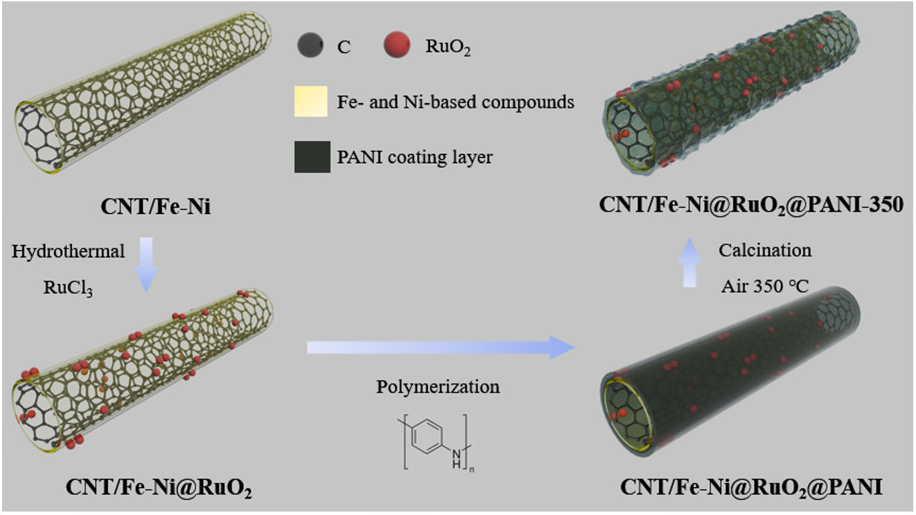
Scheme 1. Schematic illustration of the synthesis of CNT/Fe-Ni@RuO2@PANI-350.
The structure of CNT/Fe-Ni is first characterized by XRD and XPS. The diffraction peak of graphitic carbon [Supplementary Figure 3A] could be clearly observed, but the characteristic diffraction peak of Fe-Ni alloy was rather weak, indicating the particle size of the generated Fe-Ni alloy is either too small or highly dispersed in the carbon matrix. In the Fe 2p XPS spectrum [Supplementary Figure 4], the peaks at binding energies of 707.2, 711.2 and 713.3 eV correspond to Fe0, Fe2+, and Fe3+, respectively, with a satellite peak at 717.8 eV (Fe 2p3/2). Similarly, in the Ni 2p3/2 spectrum, the peaks at binding energies of 852.6, 853.8 and 855.0 eV are related to Ni0, Ni2+, and Ni3+, respectively, with a satellite peak at 861.7 eV. The existence of Fe0 and Ni0 demonstrated that they exist in metallic and/or alloying counterparts, consistent with XRD analysis. The high valence states of Fe (Fe2+, Fe3+) and Ni (Ni2+, Ni3+) might result from the surface oxidation of metallic Fe and Ni[13].
The morphology of CNT/Fe-Ni, CNT/Fe-Ni@RuO2, CNT/Fe-Ni@RuO2@PANI and CNT/Fe-Ni@RuO2@PANI-350 is investigated by transmission electron microscopy (TEM). The representative TEM image of CNT/Fe-Ni [Figure 1A] displays the nanotube with a diameter of 150 nm. The high-resolution TEM image (insert in Figure 1A) reveals an average interplanar spacing of 0.345 nm, which is assigned to the (002) crystal plane of graphite, indicating that the CNTs exhibit high crystallinity[37]. After the hydrothermal reaction at either low or high RuCl3 concentration, RuO2 nanoparticles are observed to be anchored on the surface of CNT/Fe-Ni with high uniformity, as shown in Figure 1B, indicating that Fe-Ni on the CNT/Fe-Ni surface is likely to induce a nano-confinement effect for preferentially depositing RuO2 nanoparticles on the Fe-Ni sites. Such an effect promotes strong metal-support interaction, which is expected to stabilize Ru species during the OER process. Figure 1C and D display a typical TEM image of CNT/Fe-Ni@RuO2@PANI and CNT/Fe-Ni@RuO2@PANI-350. The coating of PANI prevents the agglomeration of RuO2 nanoparticles during high-temperature treatment. The TEM image of CNT/Fe-Ni@RuO2@PANI-350 demonstrates the uniform distribution of RuO2 nanoparticles which exhibit an average size of 1.67 ± 0.27 nm [Figure 1E]. The high-resolution TEM image shown in Figure 1F reveals the high crystallinity of RuO2 nanoparticles. The lattice spacing of 0.315, 0.255 and 0.169 nm corresponded to the (110), (101) and (201) crystal planes of the rutile-structured RuO2. This observation aligns well with the selected-area electron diffraction (SAED) pattern shown in Figure 1F, which exhibits distinct diffraction rings that are assigned to the (110), (101), and (211) planes of rutile RuO2. These findings confirm the successful formation of RuO2 NPs anchored on the CNT/Fe-Ni framework.
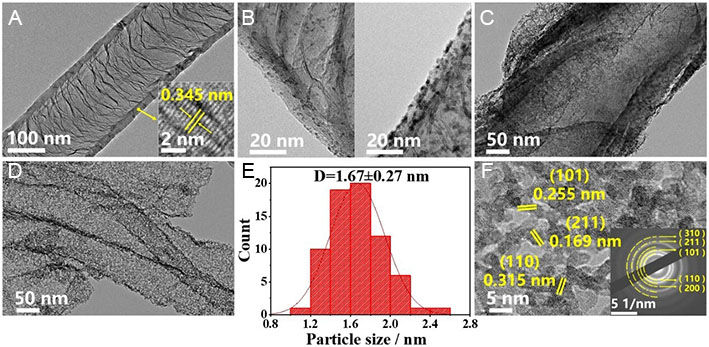
Figure 1. TEM characterization of CNT/Fe-Ni, CNT/Fe-Ni@RuO2, CNT/Fe-Ni@RuO2@PANI and CNT/Fe-Ni@RuO2@PANI-350. TEM images of (A) CNT/Fe-Ni; (B) CNT/Fe-Ni@RuO2 with low (left) and high (right) RuO2 loading; (C) CNT/Fe-Ni@RuO2@PANI, (D) CNT/Fe-Ni@RuO2@PANI-350; (E) Particle size distribution histogram of CNT/Fe-Ni@RuO2@PANI-350. (F) IFFT image of CNT/Fe-Ni@RuO2@PANI-350, inset: corresponding SAED image.
Figure 2A shows the XRD pattern of the CNT/Fe-Ni@RuO2@PANI-350 sample. The sharp peak at 26.5° is the characteristic diffraction peak of (002) crystal plane of graphitic carbon (PDF# 75-1621), and the (110), (101) and (211) crystal planes of rutile RuO2 (PDF# 71-2273) are also observed, further confirming the crystalline nature of the CNT as well as the presence of RuO2. XPS measurements were conducted to obtain more structural information about the CNT/Fe-Ni@RuO2@PANI-350 catalyst. Ru, Fe, Ni, O, C, and N elements were detected as shown in the survey XPS spectrum [Figure 2B]. Supplementary Figure 5 displays the scanning transmission electron microscopy (STEM) and EDS elemental mapping images of the CNT/Fe-Ni@RuO2@PANI-350 catalyst, demonstrating the uniform distribution of C, N, Fe, Ni throughout the CNT/Fe-Ni support as well as Ru and O from RuO2 uniformly distributed on the CNT/Fe-Ni support. The N element was introduced from the acetonitrile precursor and PANI. The high-resolution C 1s and Ru 3d spectra are shown in Figure 2C. The peak at a binding energy of 284.8 eV corresponds to the characteristic C=C bond in graphite, and the peak at a binding energy of 285.8 eV is attributed to C-N bonds in CNT/Fe-Ni@RuO2@PANI-350. For the Ru 3d spectrum, the peaks at 281.1 and 285.4 eV correspond to Ru 3d5/2 and Ru 3d3/2 of RuO2 with satellite peaks observed at 282.8 and 286.2 eV for Ru 3d5/2 and Ru 3d3/2, respectively. The XPS spectra of Fe 2p and Ni 2p for CNT/Fe-Ni@RuO2@PANI-350

Figure 2. XRD and XPS characterization of CNT/Fe-Ni@RuO2@PANI-350. (A) XRD pattern, (B) XPS survey spectrum, (C) Ru 3d and C 1s spectrum, (D) Ru 3p3/2 spectrum, (E) O 1s spectrum, and (F) N 1s spectrum.
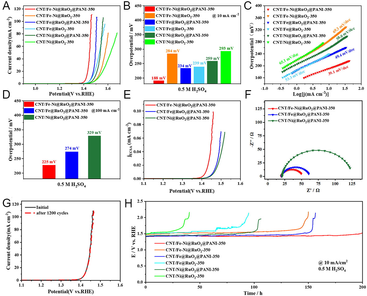
Figure 3. OER catalytic performance of different catalysts in 0.5 M H2SO4 solution. (A) OER polarization curves, (B) overpotentials at a current density of 10.0 mA cm-2, (C) Tafel plots, (D) overpotentials at a current density of 100.0 mA cm-2, (E) ECSA-normalized polarization profiles, (F) EIS spectra, (G) polarization profiles of CNT/Fe-Ni@RuO2@PANI-350 before and after OER, (H) time-dependent potential curves.
Figure 3 illustrates the OER catalytic performance of CNT/Fe-Ni@RuO2@PANI-350 in acidic conditions. Meanwhile, the OER catalytic performance of the catalyst prepared by only using ferrocene (denoted as CNT/Fe@RuO2@PANI-350) or nickelocene (denoted as CNT/Ni@RuO2@PANI-350) was also investigated for better comparison and to highlight the synergic effect of Fe-Ni alloy. As shown in Figure 3A, CNT/Fe-Ni@RuO2@PANI-350 exhibits the best OER activity, with an overpotential (ŋ10) of only ca. 188 mV at a current density of 10 mA cm-2. The overpotential (ŋ10) of CNT/Fe-Ni@RuO2@PANI-350 is significantly lower than those of CNT/Fe@RuO2@PANI-350 (234 mV), CNT/Ni@RuO2@PANI-350 (259 mV), and the other catalysts without PANI coating. The previous study has demonstrated that the catalysts with PANI modification exhibited better performance than the ones without PANI modification[38]. As displayed in Figure 3B, the ŋ10 values of CNT/Fe-Ni@RuO2@PANI-350, CNT/Fe@RuO2@PANI-350 and CNT/Ni@RuO2@PANI-350 are lower than those of CNT/Fe-Ni@RuO2-350, CNT/Fe@RuO2-350 and CNT/Ni@RuO2-350, respectively. This is potentially because the presence of PANI on the catalyst surface induces the formation of an ultra-thin carbon layer and abundant VOs in RuO2 NPs during the calcination process, resulting in the improved catalytic activity of RuO2. The corresponding Tafel plots shown in Figure 3C indicate that CNT/Fe-Ni@RuO2@PANI-350 possesses the smallest Tafel slope of only 39.1 mV dec-1. The Fe-C hetero-interface in CNT/Fe-Ni enhances the synergistic effect between metal and CNT, promoting the formation of active sites and improving catalytic activity[41,42]. Furthermore, the catalytic activity can be further enhanced by the introduction of Ni. As indicated in Figure 3D, CNT/Fe-Ni@RuO2@PANI-350 shows significantly improved OER catalytic activity compared with CNT/Fe@RuO2@PANI-350. The overpotentials at the current density of 10 and 100 mA cm-2 are reduced from 234 and 274 mV to 188 and 225 mV, respectively. Moreover, the catalytic activity of CNT/Fe-Ni@RuO2@PANI-350 surpasses that of commercial RuO2/CC (ŋ10 = 310 mV), and most reported catalysts such as B-RuO2 (ŋ10 = 200 mV)[43] and PtCo-RuO2/C (ŋ10 = 212 mV)[44] as summarized in Supplementary Table 2. These results verify the superior OER activity of CNT/Fe-Ni@RuO2@PANI-350 in acidic media. At a higher current density of 100 mA cm-2 [Figure 3D], CNT/Fe-Ni@RuO2@PANI-350 maintains a low overpotential (ŋ100) of 225 mV, which is significantly lower than those of CNT/Fe@RuO2@PANI-350 (ŋ100 = 274 mV) and CNT/Ni@RuO2@PANI-350 (ŋ100 = 329 mV). Such high-current performance is more favorable for practical applications, and the CNT/Fe-Ni@RuO2@PANI-350 catalyst exhibits remarkable advantage at the increased current density. Supplementary Figure 7 presents the OER catalytic performance of CNT/Fe-Ni, CNT/Fe-Ni@RuO2, and CNT/Fe-Ni@RuO2@PANI under acidic conditions. Combined with Figure 3A, it reveals that samples without Ru loading or calcination treatment exhibit lower catalytic activity, demonstrating the necessity of both Ru loading and calcination treatment.
The intrinsic activity of CNT/Fe-Ni@RuO2@PANI-350 towards the OER reaction is further evaluated by linear sweep voltammograms (LSVs) normalized by the ECSA. The ECSA of the catalyst can be calculated based on the Cdl value estimated by extrapolating the cyclic voltammograms (CVs) at different scan rates
DFT simulation is further used to reveal the origin of catalytic activity and stability of the CNT/Fe-Ni@RuO2@PANI-350 catalyst. Specifically, to simulate the CNT/Fe-Ni@RuO2@PANI-350 composite structure, a Fe-Ni co-doped graphene supported RuO2 (110) model (denoted as GPE/Fe-Ni@RuO2) was constructed [Figure 4A]. In the computational model of GPE/Fe-Ni@RuO2, Fe and Ni atoms are positioned adjacent to each other, representing the Fe-Ni alloy configuration. DFT calculations shown in Figure 4A reveal that the optimized Fe-O bond lengths at the interface of RuO2 clusters combined with GPE/Fe-Ni and GPE/Fe are 1.737 and 1.740 Å, respectively, which are significantly shorter than those in FeO
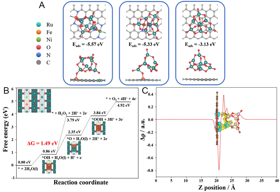
Figure 4. DFT simulations. (A) Optimized geometry of GPE/Fe-Ni@RuO2, GPE/Fe@RuO2, and GPE@RuO2; (B) OER free energy diagram, (C) charge density difference analysis of GPE/Fe-Ni@RuO2.
Charge density analysis was employed to reveal the influence of the catalyst’s electronic structure on its OER activity[47]. Figure 4C and Supplementary Figure 16 display the planar average charge density distribution curves of different catalyst models (GPE/Fe-Ni@RuO2, GPE/Fe@RuO2, and GPE@RuO2). Significant charge redistribution is observed at the interface between RuO2 (110) and graphite substrate under the synergistic effect of Fe-Ni bimetals [Figure 4C]. The yellow regions represent electron density depletion (Δρ < 0), while cyan regions indicate electron density accumulation (Δρ > 0). Local charge integration analysis shows that the presence of Fe-Ni bimetals promotes directional charge transfer from RuO2 to graphite substrate, resulting in a higher oxidation state of Ru sites. The results indicate that the distinct electronic interaction between RuO2 and graphite substrate with the synergistic effect of Fe-Ni bimetals effectively enhances the oxidation capacity of RuO2, thereby improving its OER catalytic performance[48]. In contrast, the GPE@RuO2 model exhibits minimal charge exchange between graphite substrate and RuO2 clusters in absence of Fe-Ni or Fe. Such a difference in electronic interaction between RuO2 and graphite substrate is closely related to the anchoring effect of Fe-Ni or Fe sites. Particularly, the planar average charge density curve of GPE/Fe-Ni@RuO2 shows a sharper peak at the adsorption site for RuO2, corresponding to the dual-site adsorption configuration induced by the Fe-Ni bimetallic sites. These findings at the electronic level corroborate the intrinsic mechanism that the anchoring-confinement effect of Fe-Ni bimetals on the CNT surface induces the preferential loading of RuO2 and enhances its catalytic performance.
CONCLUSIONS
In conclusion, the RuO2 nanoparticles decorated on Fe-Ni-doped CNTs have been prepared as a catalyst for OER in acidic conditions with high catalytic activity and stability. Experimental and theoretical investigations reveal that the nano-confinement effect induced by Fe-Ni bimetals on the CNT surface not only strengthens the anchoring stability of RuO2 nanoparticles, but also promotes a significant increase in the oxidation state of active-site through interfacial electron coupling. These effects boost the catalytic activity of Ru sites and enhance the surface stability of Ru during OER. As a result, the catalyst exhibits a decent OER performance with overpotential of 188 and 225 mV at a current density of 10 and 100 mA cm-2, respectively, in 0.5 M H2SO4. Notably, the catalyst sustains merely 30 mV overpotential increase throughout 150 h continuous operation at 10 mA cm-2. This study proposes a bimetallic nano-confinement strategy addressing the stability of Ru-based catalysts, potentially opening an alternative way for designing OER electrocatalysts with both high activity and long-term stability.
DECLARATIONS
Authors’ contributions
Conceptualization and supervision, review and editing: Zhao, Y.; Li, B.
Experimentation: Liu, S.; Tan, H.; Dai, G.
Investigation, methodology: Xiong, S.; Zhao, Y.; Li, B.
Materials characterization: Liu, S.; Dai, G.
Data analysis: Liu, S.; Tan, H.; Xiong, S.
Writing-original draft: Liu, S.
Availability of data and materials
All detailed materials and methods supporting the results of this study are included in the article/Supplementary Materials. Further inquiries can be directed to the corresponding author(s).
Financial support and sponsorship
This work was supported by National Natural Science Foundation of China (No. 22179031).
Conflicts of interest
All authors declared that there are no conflicts of interest.
Ethical approval and consent to participate
Not applicable.
Consent for publication
Not applicable.
Copyright
© The Author(s) 2025.
Supplementary Materials
REFERENCES
1. Gautam, J.; Lee, S.; Park, S. Strategic structural design of transition metal electrocatalysts for efficient water splitting: a comprehensive review. Nano. Today. 2024, 59, 102487.
2. Miao, H.; Zhang, D.; Shi, Y.; et al. Ultrasmall noble metal doped Ru2P@Ru/CNT as high-performance hydrogen evolution catalysts. ACS. Sustain. Chem. Eng. 2021, 9, 15063-71.
3. Frydendal, R.; Paoli, E. A.; Knudsen, B. P.; et al. Benchmarking the stability of oxygen evolution reaction catalysts: the importance of monitoring mass losses. ChemElectroChem 2014, 1, 2075-81.
4. Zhu, Y.; Wang, J.; Weiser, G.; et al. Ru single atoms and sulfur anions dual-doped NiFe layered double hydroxides for high-current-density alkaline oxygen evolution reaction. Adv. Energy. Mater. 2025, 15, 2500554.
5. Wei, J.; Tang, H.; Sheng, L.; et al. Site-specific metal-support interaction to switch the activity of Ir single atoms for oxygen evolution reaction. Nat. Commun. 2024, 15, 559.
6. Kim, J. S.; Kim, B.; Kim, H.; Kang, K. Recent progress on multimetal oxide catalysts for the oxygen evolution reaction. Adv. Energy. Mater. 2018, 8, 1702774.
7. Qin, Y.; Yu, T.; Deng, S.; et al. RuO2 electronic structure and lattice strain dual engineering for enhanced acidic oxygen evolution reaction performance. Nat. Commun. 2022, 13, 3784.
8. Hao, S.; Liu, M.; Pan, J.; et al. Dopants fixation of Ruthenium for boosting acidic oxygen evolution stability and activity. Nat. Commun. 2020, 11, 5368.
9. Zhang, L.; Jang, H.; Liu, H.; et al. Sodium-decorated amorphous/crystalline RuO2 with rich oxygen vacancies: a robust pH-universal oxygen evolution electrocatalyst. Angew. Chem. Int. Ed. 2021, 60, 18821-9.
10. Yao, Q.; Huang, B.; Zhang, N.; Sun, M.; Shao, Q.; Huang, X. Channel-rich RuCu nanosheets for pH-universal overall water splitting electrocatalysis. Angew. Chem. Int. Ed. 2019, 58, 13983-8.
11. Lin, C.; Li, J.; Li, X.; et al. In-situ reconstructed Ru atom array on α-MnO2 with enhanced performance for acidic water oxidation. Nat. Catal. 2021, 4, 1012-23.
12. Shi, Z.; Li, J.; Wang, Y.; et al. Customized reaction route for ruthenium oxide towards stabilized water oxidation in high-performance PEM electrolyzers. Nat. Commun. 2023, 14, 843.
13. Al, Zoubi. W.; Al, Mahmud. A.; Hazmatulhaq, F.; et al. Origin of the synergistic effects of bimetallic nanoparticles coupled with a metal oxide heterostructure for accelerating catalytic performance. SusMat 2024, 4, e216.
14. Zoubi W, Sheng Y, Hussain I, Seongjun H, Thalji MR, Park N. Synthesis and machine learning prediction of high entropy multi-principal element nanoparticles. Small 2025, 21, e2501444.
15. Wu, Z. Y.; Chen, F. Y.; Li, B.; et al. Non-iridium-based electrocatalyst for durable acidic oxygen evolution reaction in proton exchange membrane water electrolysis. Nat. Mater. 2023, 22, 100-8.
16. Zheng, X.; Yang, J.; Xu, Z.; et al. Ru-Co pair sites catalyst boosts the energetics for the oxygen evolution reaction. Angew. Chem. Int. Ed. 2022, 61, e202205946.
17. Liu, L.; Ji, Y.; You, W.; et al. Trace lattice S inserted RuO2 flexible nanosheets for efficient and long-term acidic oxygen evolution catalysis. Small 2023, 19, e2208202.
18. Liu, H.; Zhang, Z.; Fang, J.; et al. Eliminating over-oxidation of ruthenium oxides by niobium for highly stable electrocatalytic oxygen evolution in acidic media. Joule 2023, 7, 558-73.
19. Zhang, C.; Wang, J.; Ma, H.; et al. Electronic structure engineering of NiFe hydroxide nanosheets via ion doping for efficient OER electrocatalysis. Chem. Eng. J. 2024, 499, 156430.
20. Zheng, S.; Xu, H.; Zhu, H.; et al. Heterostructured electrocatalysts for the oxygen evolution reaction. J. Mater. Chem. A. 2024, 12, 18832-65.
21. Wang, H.; Fan, W.; Yang, S.; et al. Deeply understanding electrocatalytic oxygen evolution reaction from the perspective of defect structures. Chem. Eng. J. 2024, 499, 156124.
22. Zhang, J.; Chen, Q.; Zhao, P.; et al. Room temperature synthesis of gradient-distributed Ni/Fe sites in layered double hydroxides for enhanced oxygen evolution reaction. Small 2025, 21, e2409265.
23. Mu, X.; Yu, M.; Liu, X.; et al. High-entropy ultrathin amorphous metal-organic framework-stabilized Ru(Mo) dual-atom sites for water oxidation. ACS. Energy. Lett. 2024, 9, 5763-70.
24. González-ingelmo, M.; García, M. L.; Oropeza, F. E.; et al. Ultra-high dispersion of Ni-based OER catalysts on graphene 3D networks enhances the in situ Fe3+ catalytic activation. J. Mater. Chem. A. 2023, 11, 24248-60.
25. Zuo, S.; Wu, Z. P.; Zhang, G.; et al. Correlating structural disorder in metal (Oxy)hydroxides and catalytic activity in electrocatalytic oxygen evolution. Angew. Chem. Int. Ed. 2024, 63, e202316762.
26. Gao, T.; Kumar, K. S.; Yan, Z.; et al. Covalent organic framework derived synthesis of Ru embedded in carbon nitride for hydrogen and oxygen evolution reactions. J. Mater. Chem. A. 2023, 11, 19338-48.
27. Wang, Y.; Zhao, L.; Ma, J.; Zhang, J. Confined interface transformation of metal-organic frameworks for highly efficient oxygen evolution reactions. Energy. Environ. Sci. 2022, 15, 3830-41.
28. Zhang, D.; Miao, H.; Wu, X.; et al. Scalable synthesis of ultra-small Ru2P@Ru/CNT for efficient seawater splitting. Chin. J. Catal. 2022, 43, 1148-55.
29. Kresse, G.; Furthmüller, J. Efficiency of ab-initio total energy calculations for metals and semiconductors using a plane-wave basis set. Comput. Mater. Sci. 1996, 6, 15-50.
30. Kresse, G.; Furthmüller, J. Efficient iterative schemes for ab initio total-energy calculations using a plane-wave basis set. Phys. Rev. B. Condens. Matter. 1996, 54, 11169-86.
31. Kresse, G.; Hafner, J. Ab initio molecular-dynamics simulation of the liquid-metal-amorphous-semiconductor transition in germanium. Phys. Rev. B. Condens. Matter. 1994, 49, 14251-69.
32. Torres, E.; Kaloni, T. Projector augmented-wave pseudopotentials for uranium-based compounds. Comput. Mater. Sci. 2020, 171, 109237.
33. Perdew, J. P.; Burke, K.; Ernzerhof, M. Generalized gradient approximation made simple. Phys. Rev. Lett. 1996, 77, 3865-8.
34. Grimme, S.; Antony, J.; Ehrlich, S.; Krieg, H. A consistent and accurate ab initio parametrization of density functional dispersion correction (DFT-D) for the 94 elements H-Pu. J. Chem. Phys. 2010, 132, 154104.
35. Nørskov, J. K.; Rossmeisl, J.; Logadottir, A.; et al. Origin of the overpotential for oxygen reduction at a fuel-cell cathode. J. Phys. Chem. B. 2004, 108, 17886-92.
36. Wang, V.; Xu, N.; Liu, J.; Tang, G.; Geng, W. VASPKIT: a user-friendly interface facilitating high-throughput computing and analysis using VASP code. Comput. Phys. Commun. 2021, 267, 108033.
37. Jin, H.; Li, Z.; Wang, L.; Zeng, Q. Fabrication and properties of CNT /Ni/Y/ZrB2 nanocomposites reinforced in situ. J. Am. Ceram. Soc. 2018, 101, 1747-53.
38. Yan, H.; Jiang, Z.; Deng, B.; Wang, Y.; Jiang, Z. Ultrathin carbon coating and defect engineering promote RuO2 as an efficient catalyst for acidic oxygen evolution reaction with super-high durability. Adv. Energy. Mater. 2023, 13, 2300152.
39. Xu, Z.; Wang, S.; Tu, W.; et al. A superior bifunctional electrocatalyst in which directional electron transfer occurs between a Co/Ni alloy and Fe-N-C support. Small 2024, 20, e2401730.
40. Das, D.; Santra, S.; Nanda, K. K. In Situ fabrication of a nickel/molybdenum carbide-anchored n-doped graphene/CNT hybrid: an efficient (Pre)catalyst for OER and HER. ACS. Appl. Mater. Interfaces. 2018, 10, 35025-38.
41. Wang, H.; Luan, X.; Li, H.; et al. Ru-M (Fe, Co, Ni) onto nitrogen-doped two-dimensional carbon nanosheets through microwave approach with strong metal-support interactions for overall water-splitting. Chem. Eng. J. 2024, 502, 158063.
42. Gao, T.; Zhou, C.; Chen, X.; Huang, Z.; Yuan, H.; Xiao, D. Surface in situ self-reconstructing hierarchical structures derived from ferrous carbonate as efficient bifunctional iron-based catalysts for oxygen and hydrogen evolution reactions. J. Mater. Chem. A. 2020, 8, 18367-75.
43. Liu, C.; Sheng, B.; Zhou, Q.; et al. Motivating Ru-bri site of RuO2 by boron doping toward high performance acidic and neutral oxygen evolution. Nano. Res. 2022, 15, 7008-15.
44. Jin, H.; Choi, S.; Bang, G. J.; et al. Safeguarding the RuO2 phase against lattice oxygen oxidation during acidic water electrooxidation. Energy. Environ. Sci. 2022, 15, 1119-30.
45. Zagalskaya, A.; Alexandrov, V. Role of defects in the interplay between adsorbate evolving and lattice oxygen mechanisms of the oxygen evolution reaction in RuO2 and IrO2. ACS. Catal. 2020, 10, 3650-7.
46. Fang, Y. H.; Liu, Z. P. Mechanism and Tafel lines of electro-oxidation of water to oxygen on RuO2(110). J. Am. Chem. Soc. 2010, 132, 18214-22.
47. Lu, T.; Chen, F. Multiwfn: a multifunctional wavefunction analyzer. J. Comput. Chem. 2012, 33, 580-92.
Cite This Article
How to Cite
Download Citation
Export Citation File:
Type of Import
Tips on Downloading Citation
Citation Manager File Format
Type of Import
Direct Import: When the Direct Import option is selected (the default state), a dialogue box will give you the option to Save or Open the downloaded citation data. Choosing Open will either launch your citation manager or give you a choice of applications with which to use the metadata. The Save option saves the file locally for later use.
Indirect Import: When the Indirect Import option is selected, the metadata is displayed and may be copied and pasted as needed.
About This Article
Copyright

Data & Comments
Data
0


Comments
Comments must be written in English. Spam, offensive content, impersonation, and private information will not be permitted. If any comment is reported and identified as inappropriate content by OAE staff, the comment will be removed without notice. If you have any queries or need any help, please contact us at [email protected].