


3D-printed hydrogel and Joule-heating synthesis of Pt single-atom and nanoparticle electrodes for HER
 0
0 Abstract
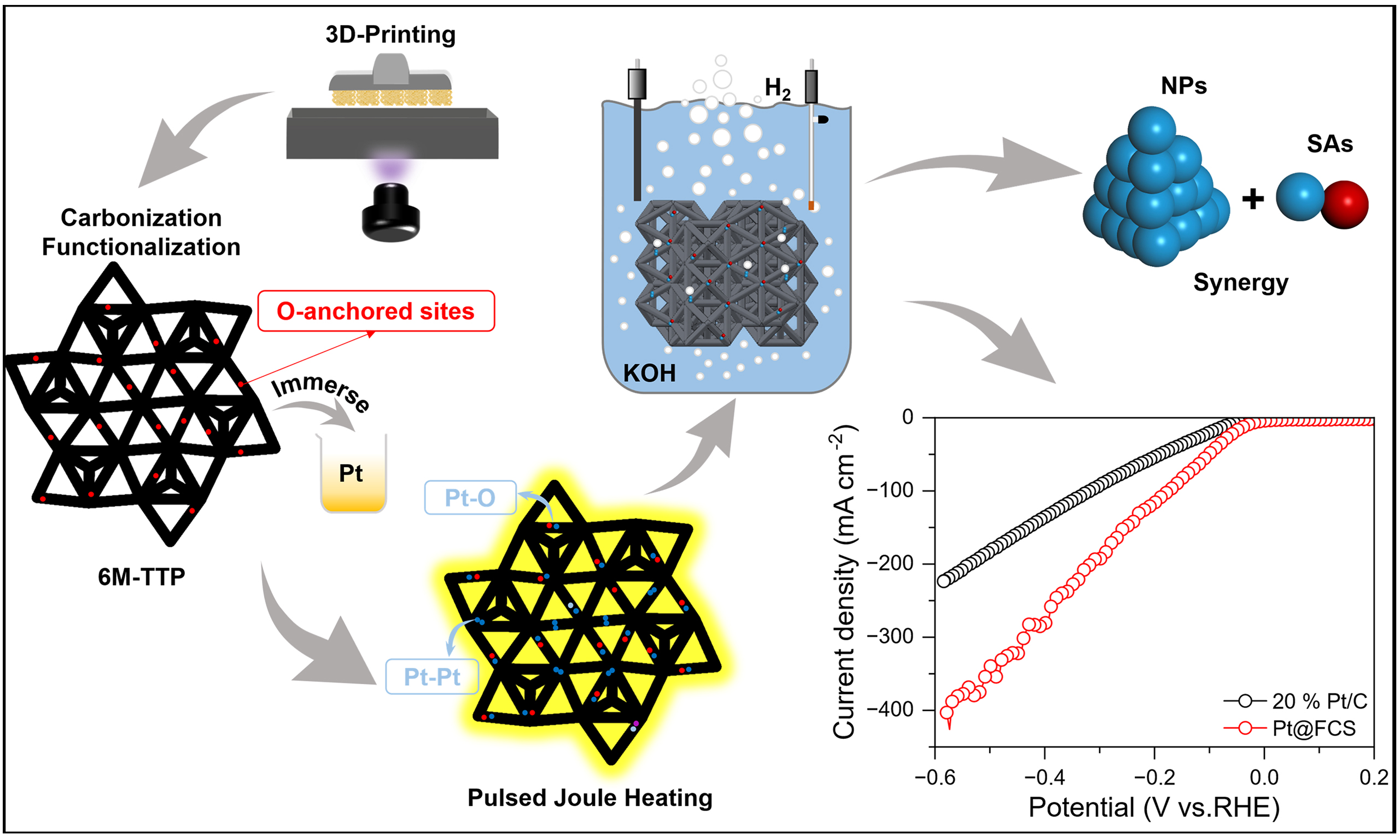
Electrocatalysts for the hydrogen evolution reaction (HER) are critical for sustainable hydrogen production, yet simultaneously achieving high activity, atom-efficient noble-metal use and integrated fabrication remains challenging. Herein, we report a scalable strategy for fabricating integrated electrodes by combining 3D-printed hydrogel templating with ultrafast pulsed Joule heating. In detail, a 3D-printed hydrogel scaffold is transformed into an oxygen-functional hierarchical carbon support that anchors oxygen-coordinated Pt single atoms (SAs) with finely dispersed Pt nanoparticles (NPs). The resulting integrated SA/NP hybrid electrode exhibits greatly increased surface area and a micro-mesoporous architecture, which suppresses NP agglomeration, increases active-site density and improves charge transfer. First-principles calculations reveal that Pt NP primarily drives water dissociation and H* generation, while adjacent Pt SA enhances the active-site utilization of Pt NP and facilitates OH* transfer, together accelerating the HER pathway. As a result, the fabricated electrode delivers low overpotentials of 33, 103, and 173 mV at current densities of 10, 50, and 100 mA cm-2, respectively, while also demonstrating remarkable durability. Beyond providing a practical route to atom-efficient HER electrodes, this integrated strategy uniquely combines a 3D-printed topological scaffold with ultrafast Joule heating to achieve synergistic Pt SA/NP sites, significantly enhancing both structural stability and catalytic kinetics, offering a great promise for next-generation energy-catalysis technologies.
Keywords
INTRODUCTION
The accelerating shift toward a hydrogen-based energy infrastructure has intensified the demand for efficient and economically viable electrochemical water-splitting technologies[1-3]. At the heart of this process lies the hydrogen evolution reaction (HER), whose performance is governed by the activity and stability of the cathode electrocatalyst[4-7]. Among all known catalysts, Pt exhibits the highest and most reliable HER activity across the entire pH range[8,9]. However, the high price and limited availability of Pt still impose a substantial bottleneck for large-scale hydrogen production, posing a major obstacle to industrial deployment[10-12]. To address this issue, downsizing Pt into nanoparticles (NPs) or even atomically dispersed single atoms (SAs) has emerged as a promising strategy. This approach maximizes atom utilization while retaining, or even enhancing, intrinsic catalytic efficiency, and has therefore attracted broad interest from both academia and industry[13].
Despite such progress, the catalytic performance of either Pt SAs or Pt NPs alone remains intrinsically limited, as each provides only part of the functionality required for fast and sustainable HER kinetics[14]. Recent studies have revealed that constructing hybrid catalysts containing both SAs and NPs can unlock synergistic benefits. Specifically, SAs with well-defined coordination environments offer favorable hydrogen adsorption energetics, while NPs provide extended metallic ensembles that promote water adsorption, dissociation, and rapid electron transfer[15,16]. When these atomic and nanoscale sites coexist within a rationally designed framework, their electronic and structural interactions lead to optimized H* binding, accelerated reaction pathways, and enhanced operational durability[17]. However, realizing such intimate and coherent SA/NP configurations in a controllable and scalable manner remains challenging, especially when aiming for industrial applications.
For practical water-electrolysis systems, the catalytic powder must ultimately be integrated into a mechanically robust, binder-free, and conductive electrode. This integration step introduces additional challenges[18]. Traditional slurry-coating approaches commonly induce poor dispersion, increased interfacial resistance, and partial blockage of active sites, limiting both performance and reproducibility[19,20]. Three-dimensional (3D) printing has therefore emerged as a promising alternative due to its ability to tailor macroscopic architecture, porosity, and mass-transport pathways with high precision[21,22]. Among various printable media, hydrogel-based 3D printing is particularly attractive, as the resulting viscoelastic networks can maintain structural fidelity while providing rich functional groups for subsequent conversion into carbon frameworks[23]. Nevertheless, the thermal treatments required to carbonize hydrogels and incorporate metal species often lead to structural shrinkage, defect accumulation, or uncontrolled NP growth[24]. In this context, ultrafast pulsed Joule heating has recently emerged as a powerful materials processing technique capable of reaching extremely high temperatures within milliseconds, providing a potential way to achieve the combination of carbon matrix and atoms[25]. Meanwhile, the Joule heating is also well suited for triggering the formation of diverse nanomaterials on carbon-based substrates[4]. These advantages motivate us to develop a combined 3D-printing Joule-heating strategy capable of fabricating integrated electrodes coupled with Pt SAs or NPs, thereby addressing both catalytic and manufacturing challenges in HER electrocatalysis.
Here, we report an integrated electrode fabrication strategy that combines hydrogel-based 3D printing with ultrafast pulsed Joule heating to construct Pt SA/NP hybrid electrodes for efficient HER. This approach introduces key innovations in both electrode architecture and fabrication methodology. The 3D-printed template adopts a six-membered triple-top triangular prism (6M-TTP) geometry, originating from a medium-range order structural motif in amorphous alloys. This design not only creates a well-defined porous architecture that facilitates mass transport, but also allows for uniform stress distribution and effective stress release. These features collectively enhance the structural integrity and long-term stability of the integrated electrode, an advantage that is difficult to achieve with traditional powder-coated electrodes. In addition, by combining additive manufacturing[26] with ultrafast Joule heating, we develop a seamless “macro-to-atomic” fabrication route that directly produces binder-free integrated electrodes. This approach avoids the increased interfacial resistance and active site burial commonly associated with conventional slurry-coating methods. This work highlights the potential of combining 3D printing with ultrafast thermal engineering to advance practical hydrogen-evolution technologies.
EXPERIMENTAL
Materials
All chemical reagents were of analytical grade and used as received, provided by Shanghai Maier Biochemical Technology Co., Ltd. Including poly(ethylene glycol) diacrylate (PEGDA), N, N-dimethylformamide (DMF), platinum (IV) chloride (PtCl4), and potassium hydroxide (KOH) were purchased from Shanghai MaiRu Biochemical Technology Co., Ltd. Photoinitiators including 2-(dimethylamino)-2-(4-methylbenzyl)-1-(4-morpholinophenyl)butan-1-one (Irgacure 379), 4,4’-di(N, N-dimethylamino) benzophenone (Michler’s ketone), and the photoabsorber 1-(phenyldiazenyl)naphthalen-2-ol (Sudan I). Nitric acid (HNO3, 65%-68%) and hydrogen peroxide (H2O2, 30%) were employed for oxidation treatment.
Sample preparation
Fabrication of 3D-printed hydrogel scaffold
A printable slurry was prepared by dissolving 694 mg Irgacure 379, 458 mg Michler’s ketone, and 20.6 mg Sudan I in 20 mL of DMF under stirring at 25 °C and 600 rpm for 24 h. Subsequently, 70 mL PEGDA was added to the solution and mixed thoroughly. The homogeneous resin was printed into a micro-nano lattice organogel adopting a 6M-TTP geometry using a commercial 405 nm digital light processing (DLP) printer. The as-printed structure was immersed in DMF at 70 °C for 1 h and subsequently exchanged into deionized water to remove unreacted residues.
Carbonization of hydrogel
The carbonization profile was established based on thermogravimetric analysis (TGA) performed under argon (10 °C/min to 800 °C). The organogel was sintered in a tube furnace under a high-purity argon atmosphere (purity ≥ 99.99%). The heat treatment involved heating to 250 °C at 1 °C/min, then gradually to 600 °C at 0.5 °C/min holding for 1 h, followed by rapid heating to 900 °C at 10 °C/min and maintaining for
Functionalization of the CS
The CS was functionalized using a mixed acid solution prepared by combining 20 mL of HNO3 (10, 20, 30, 40, or 50 mol%) with 10 mL of 30 mol% H2O2. The mixture was transferred to a 100 mL Teflon-lined autoclave for hydrothermal treatment at 120 °C for 5 h. The product obtained after acid activation was washed repeatedly with deionized water until a neutral pH (6-7) was reached, yielding the functionalized carbon support (FCS).
Synthesis of Pt@FCS and Pt@CS
Pt precursor solutions were prepared by dissolving PtCl4 in deionized water to obtain Pt concentrations of 0.08, 0.4, 2, 4, and 10 mM. The FCS was then impregnated in the precursor solutions at 70 oC for 12 h and dried at 70 oC for 30 min. Joule heating (HTS-7026D, Shenzhen Zhongke Jingyan Technology Co., Ltd.) was subsequently carried out by sandwiching the impregnated scaffold between two carbon-cloth electrodes and applying pulsed current (30 A, 32 V) under argon. Samples were treated using different heating temperatures (700, 800, 900, 1,000, 1,200, and 1,300 oC) and pulse numbers (1, 5, 10, and 15 pulses), with each pulse having a 50 ms ON-state. This process yielded the Pt SA/NP hybrid electrode denoted as Pt@FCS, whereas the counterpart without CS functionalization is denoted as Pt@CS.
Characterizations
TGA was conducted on a Mettler-Toledo TGA/differential scanning calorimetry (DSC) 3+ (Greifensee, Switzerland) under argon at 10 °C/min. X-ray diffraction (XRD) patterns were recorded on a Bruker D8 Advance diffractometer (Karlsruhe, Germany). Morphology and elemental distribution were examined using scanning electron microscopy (SEM, JSM-7800F PRIME, JEOL, Japan) with energy-dispersive X-ray spectroscopy (EDS) and aberration-corrected scanning transmission electron microscopy (AC-STEM, Titan Cubed Themis G2 300, Thermo Fisher Scientific, USA). Raman spectra were acquired on a confocal Raman microscope (inVia, Renishaw, UK) with a 532 nm laser. Fourier-transform infrared (FT-IR) spectra were collected on a Bruker ALPHA II spectrometer (Germany). Surface chemical states were analyzed by X-ray photoelectron spectroscopy (XPS, PHI QUANTERA II, ULVAC-PHI, Japan). The Pt content was quantified by inductively coupled plasma optical emission spectrometry (ICP-OES, iCAP 7000, Thermo Fisher Scientific, USA). N2 adsorption/desorption isotherms were measured at 77 K on a Micromeritics ASAP 2460 instrument (USA). The specific surface area and pore size of CS/FCS were calculated using the Brunauer-Emmett-Teller (BET) method. X-ray absorption fine structure (XAFS) measurements were conducted at the BL13W beamline of the Shanghai Synchrotron Radiation Facility (SSRF, Shanghai, China)[27]. The Pt L3-edge XAFS data were collected in fluorescence detection mode. The center energy of the radiated X-rays was 50.00 keV, corresponding to a wavelength of 0.2480 Å. Samples were exposed to air at room temperature throughout the experiments. The data, including X-ray absorption near edge structure (XANES) and extended X-ray absorption fine structure (EXAFS), were analyzed using the ATHENA software package (Demeter, Chicago, USA)[28]. The Fourier transform window range for the k-space is from 2.5 to 10 Å-1.
Electrochemical testing
Electrochemical measurements were performed in a standard three-electrode configuration, employing a carbon rod as the counter electrode and a Hg/HgO electrode as the reference. The electrolyte was 1.0 M KOH, and its pH was determined to be 13.8 using a calibrated pH meter (INESA, Shanghai INESA Scientific Instrument Co., Ltd., China) prior to each measurement. All measured potentials were converted to the reversible hydrogen electrode (RHE) scale according to the Nernst equation[29]:
All linear sweep voltammetry (LSV) curves presented in this work have been corrected to the RHE scale using this conversion. The working electrode was electrochemically conditioned by multiple activation cycles. LSV was then conducted between -1.5 and -0.6 V vs. RHE at a sweep rate of 10 mV s-1 until a steady response was achieved. To estimate the electrochemically active surface area (ECSA), the double-layer capacitance (Cdl) was derived from cyclic voltammetry (CV) measurements recorded in the non-faradaic region (-0.1 to 0 V vs. Hg/HgO) at scan rates of 20, 40, 60, 80, 100, and 120 mV s-1. Electrochemical impedance spectroscopy (EIS) measurements were carried out at -0.95 V vs. RHE over a frequency range of 100 kHz to 0.1 Hz with an alternating current (AC) perturbation of 5 mV.
Computational method
Spin-polarized density functional theory (DFT) computations were carried out employing the projected augmented wave (PAW) method, as implemented in the Vienna Ab Initio Simulation Package (VASP)[30,31]. Electron exchange-correlation interactions were treated using the Perdew-Burke-Ernzerhof (PBE) functional within the generalized gradient approximation (GGA)[32]. The plane-wave basis was expanded with a kinetic energy cutoff of 400 eV, and Brillouin zone sampling was performed using a 3 × 3 × 1 k-point mesh. A 20 Å vacuum gap was applied along the direction perpendicular to the slab to avoid spurious interactions between periodic images. Structural relaxations were carried out until the total energy change was less than 10-4 eV.
The adsorption energy of OH* and H* was calculated using[33]:
where Eslab is the total energy of the PtSA + PtNP. Eslab+OH and Eslab+H are the corresponding total energies with OH* and H*. EH2O and EH2 are the total energies of the H2O and H2 molecules. The free energy is calculated using[34]:
where ΔZPE, ΔEH*, and ΔS denote the changes in zero-point energy, hydrogen adsorption energy, and entropy, respectively. Following the work of Nørskov et al., the correction term ΔZPE - TΔS was taken as
RESULTS AND DISCUSSION
Figure 1A illustrates the overall fabrication route for constructing Pt SA/NP hybrid electrodes for HER using a hydrogel 3D-printing Joule-heating strategy. The process begins with printing a hydrogel scaffold based on the 6M-TTP structural model [Supplementary Figure 1A], followed by staged calcination under argon to form conductive CS [Supplementary Figure 1B]. According to TGA analysis [Supplementary Figure 2A and B], a significant mass loss was revealed between 223-482 °C, corresponding to the decomposition of the hydrogel matrix. Guided by this, a slow stepwise-heating protocol from 250 to 600 °C with a 1-hour holding period at 600 °C was adopted to ensure gradual removal of organics and preserve the framework geometry. Subsequently, a 4-hour holding period at 900 °C was introduced to promote carbonization of CS and enhance electrical conductivity. A mild surface treatment was then applied to remove residual pyrolytic particulates and generate abundant pores, ultimately producing the FCS [Supplementary Figure 2C].
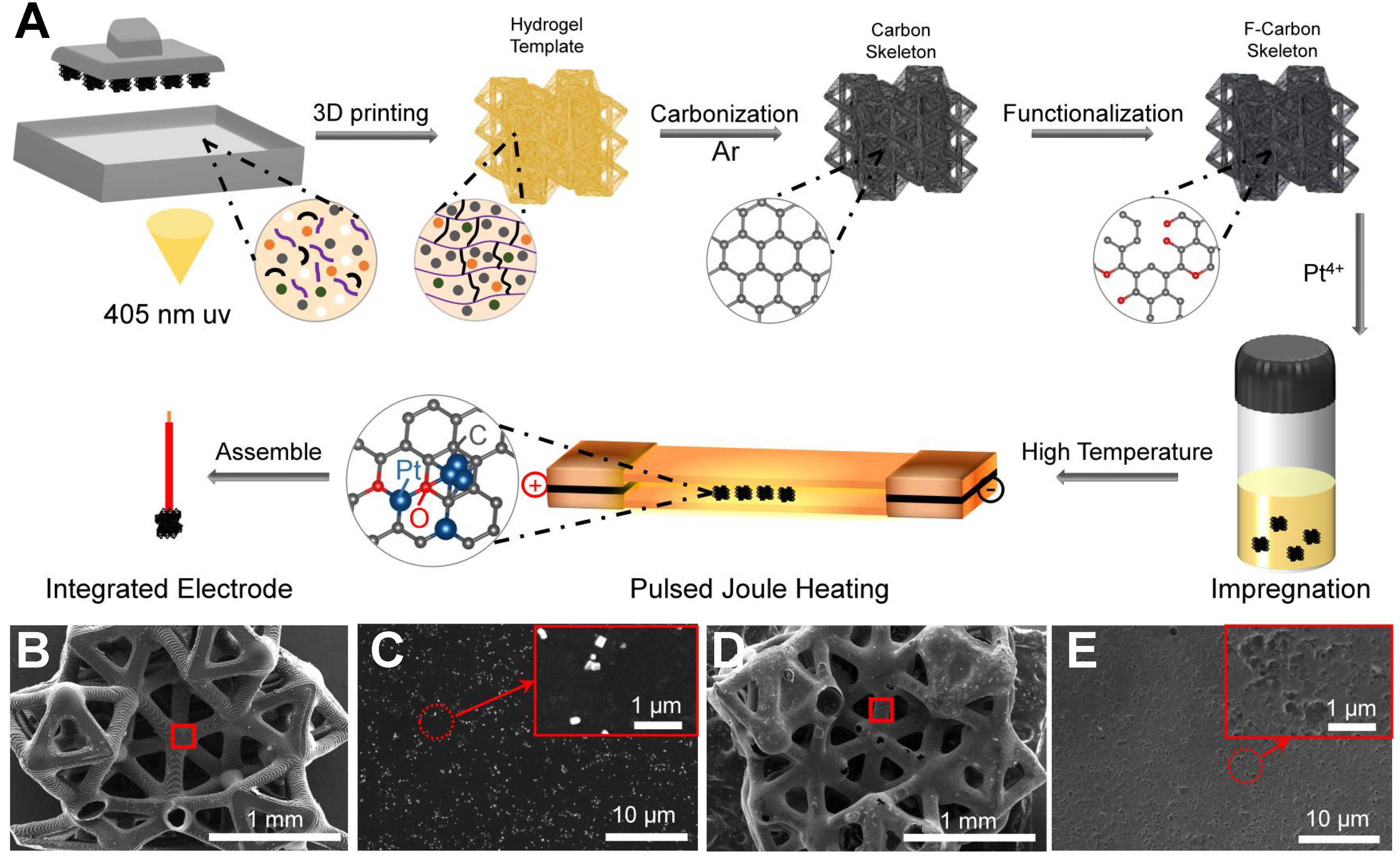
Figure 1. (A) Schematic diagram of the fabrication route for Pt SA/NP hybrid electrode based on 3D-printed hydrogel templates; (B) SEM image of CS with (C) high-magnification views showing surface particulate residues. The areas outlined in red in (B) correspond to the magnified regions shown in (C); (D) SEM images of FCS with (E) high-magnification views showing the formation of hierarchical porous structures. The areas outlined in red in (D) correspond to the magnified regions shown in (E). SA: Single atom; NP: nanoparticle; 3D: three-dimensional; SEM: scanning electron microscopy; CS: carbon support; FCS: functionalized carbon support.
As observed in Figure 1B, the magnified region of the CS framework contains abundant particulate residues originating from the incomplete pyrolysis of the hydrogel precursor. High-magnification imaging [Figure 1C] demonstrates that these residues persist as irregular aggregates attached to the CS surface, resulting in a rough and heterogeneous microstructure. In contrast, the FCS presents a clean surface with pyrolytic residues fully removed [Figure 1D], and the enlarged branch-like domains reveal the formation of a continuous porous network [Figure 1E]. This morphological evolution confirms that the functionalization process purifies the carbon framework and creates abundant accessible pores. These features facilitate the subsequent anchoring of Pt species. As revealed by nitrogen adsorption-desorption isotherms
Pt loading and stabilization were achieved via the ultrafast Joule heating method with a controlled number of pulses (see Experimental Section). As shown in the temperature profile [Supplementary Figure 4A], a single pulse heats the scaffold to ~800 °C within ~0.15 s, followed by immediate current cutoff and cooling in
To investigate the evolution of surface functional groups before and after acid activation, FT-IR spectroscopy was performed [Figure 2A]. In comparison with CS, the FCS obtained via HNO3-H2O2 treatment exhibits enhanced absorption bands at ~1,574 and ~1,726 cm-2, fingerprinting carbonyl (C=O) stretching vibrations. This confirms the successful incorporation of oxygen-containing groups into the carbon framework, which is expected to improve the Pt dispersion during subsequent loading. Notably, the characteristic signals of these oxygen-containing functional groups remained clearly detectable even after ten cycles of pulse Joule heating treatment [Supplementary Figure 6], indicating that these groups were well preserved during the ultrafast high-temperature process, thereby providing crucial coordination sites for the in-situ anchoring of Pt atoms. XRD analysis reveals that the carbon frameworks of CS and FCS exhibit nearly identical diffraction features [Supplementary Figure 7] with both showing two broad peaks at ~26° and ~44°, corresponding to (002) and (100) planes of graphitic carbon. These patterns indicate that both materials possess partially graphitized carbon structures, ensuring high electrical conductivity[37,38], and acid functionalization does not alter the average atomic arrangement of the carbon framework. In contrast, after Pt loading, the two electrodes display remarkably different XRD features [Figure 2B]. The Pt@CS exhibits distinct Bragg reflections indexed to metallic Pt (PDF#87-0636), indicating the formation of large Pt particles. Conversely, the absence of Pt diffraction peaks in Pt@FCS is attributed to the oxygen-containing functional groups introduced by acid treatment. These groups form strong Pt-O-C interactions that effectively anchor Pt atoms and suppress their migration and aggregation during ultrafast Joule heating. Consequently, atomic dispersion is favored over the formation of large crystalline particles, implying that Pt exists predominantly as Pt SAs or ultra-small clusters without long-range lattice coherence. Moreover, Raman spectroscopy shows that both samples exhibit the characteristic D and G bands at ~1,340 and ~1,586 cm-1 [Figure 2C], corresponding to the defect-induced vibration mode of disordered carbon and the in-plane sp2-hybridized graphitic carbon, respectively[39,40]. Notably, the Pt@FCS exhibits a slightly higher ID/IG ratios compared to Pt@CS (1.00 vs. 0.97), suggesting a greater concentration of defect sites generated during the functionalization process. These defects increase the hydrophilicity and surface accessibility of the carbon framework[41], thereby improving the wetting and penetration of the Pt precursor solution.
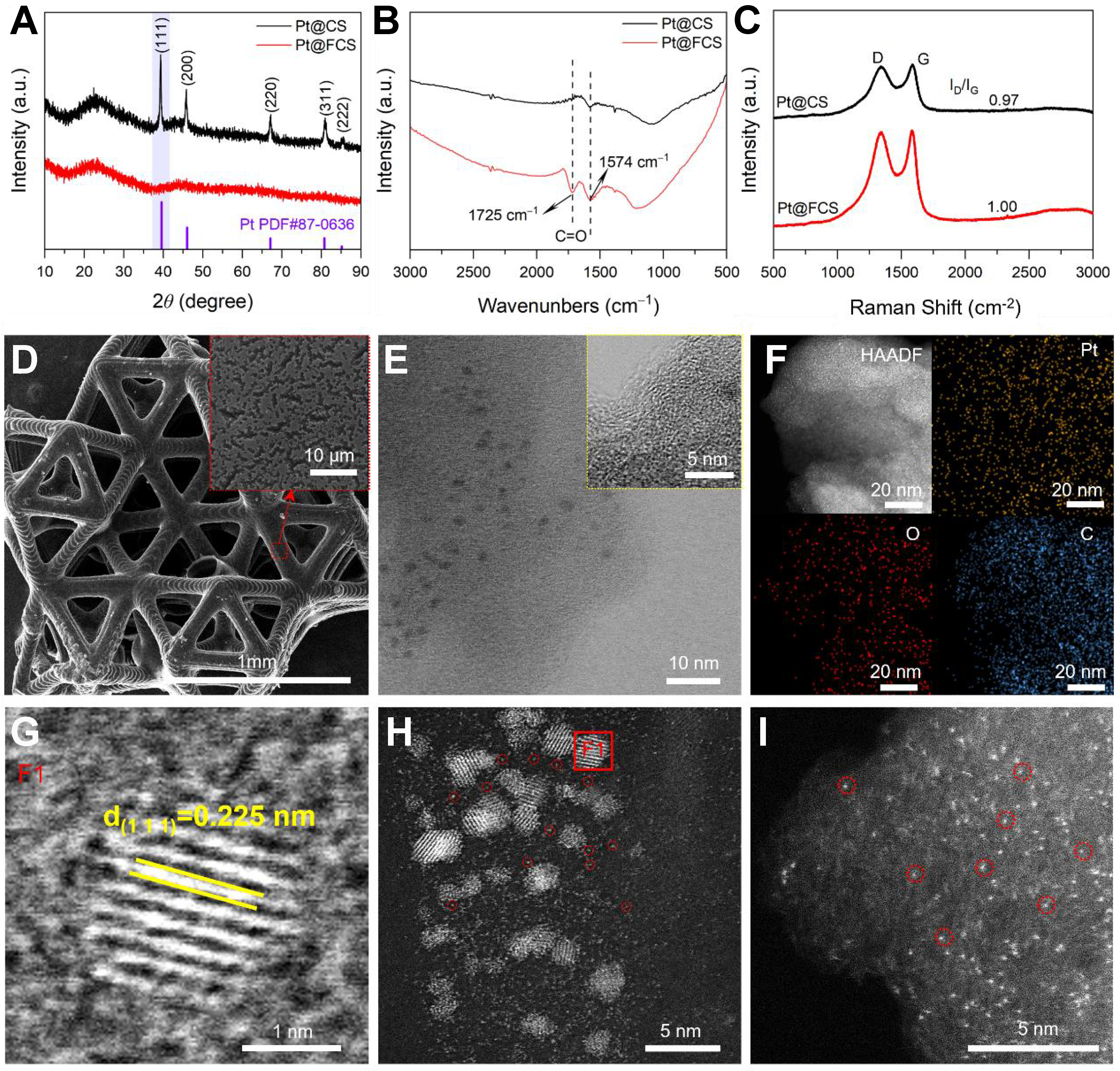
Figure 2. (A) FT-IR spectra of CS and FCS; (B) XRD patterns of Pt@CS and Pt@FCS. The purple vertical lines indicate the standard diffraction peaks of metallic Pt (PDF#87-0636); (C) Raman spectra of Pt@CS and Pt@FCS; (D) SEM image of the Pt@FCS, with an enlarged view of the marked region shown in the inset; (E) HRTEM images Pt@FCS, with the inset showing a higher-magnification view of the boxed area and (F) EDS elemental mapping of Pt@FCS; (G) HRTEM image of a single Pt nanocluster in Pt@FCS, corresponding to the area marked by the F1 in (H); (H) HAADF-STEM images of Pt@FCS highlighting ultrafine Pt NPs and (I) atomically dispersed Pt on FCS. FT-IR: Fourier-transform infrared; CS: carbon support; FCS: functionalized carbon support; XRD: X-ray diffraction; SEM: scanning electron microscopy; HRTEM: high-resolution transmission electron microscopy; EDS: energy-dispersive X-ray spectroscopy; HAADF-STEM: high-angle annular dark field scanning transmission electron microscopy; NPs: nanoparticles.
SEM [Figure 2D] and corresponding EDS analyses [Supplementary Figure 8] show that the Pt@FCS preserves the well-defined 6M-TTP nano-micro lattice while displaying no observable Pt aggregation. In contrast, the Pt@CS exhibits obvious particle agglomeration [Supplementary Figure 9]. AC-STEM further highlights the sharp contrast between these two electrodes. As shown in the high-angle annular dark field scanning transmission electron microscopy (HAADF-STEM) images [Supplementary Figure 10], dense Pt agglomerates appear on Pt@CS. For the Pt@FCS, distinct graphitic lattice fringes are revealed [Figure 2E], confirming the structural integrity of the functionalized carbon framework. The locally observed dark-contrast domains (1-2 nm) correspond to Pt nanoclusters, whose higher atomic number leads to stronger electron scattering and thus pronounced contrast. In addition, there are also atomically dispersed Pt and O species on the FCS framework, as validated by elemental mapping of homogeneous distributions of Pt and O [Figure 2F]. The Pt NPs loaded on Pt@FCS display a lattice spacing of 0.225 nm [Figure 2G], corresponding to the (111) planes of face-centered cubic Pt[42]. These structural details confirm the crystalline nature of the Pt NPs. Figure 2H and I also reveal the presence of ultrafine Pt NPs and numerous isolated Pt SAs decorating the carbon surface. This is consistent with the increased defect density and hydrophilicity induced by surface functionalization, which collectively inhibit Pt ripening and promote atomic-scale dispersion.
XPS analysis provides further evidence of the distinct Pt dispersion states on FCS and CS. Survey spectra show weaker Pt signals for Pt@FCS [Figure 3A], consistent with the suppressed formation of large surface-exposed Pt particles. In the Pt 4f region [Figure 3B], Pt@CS exhibits both metallic Pt0 (71.4/
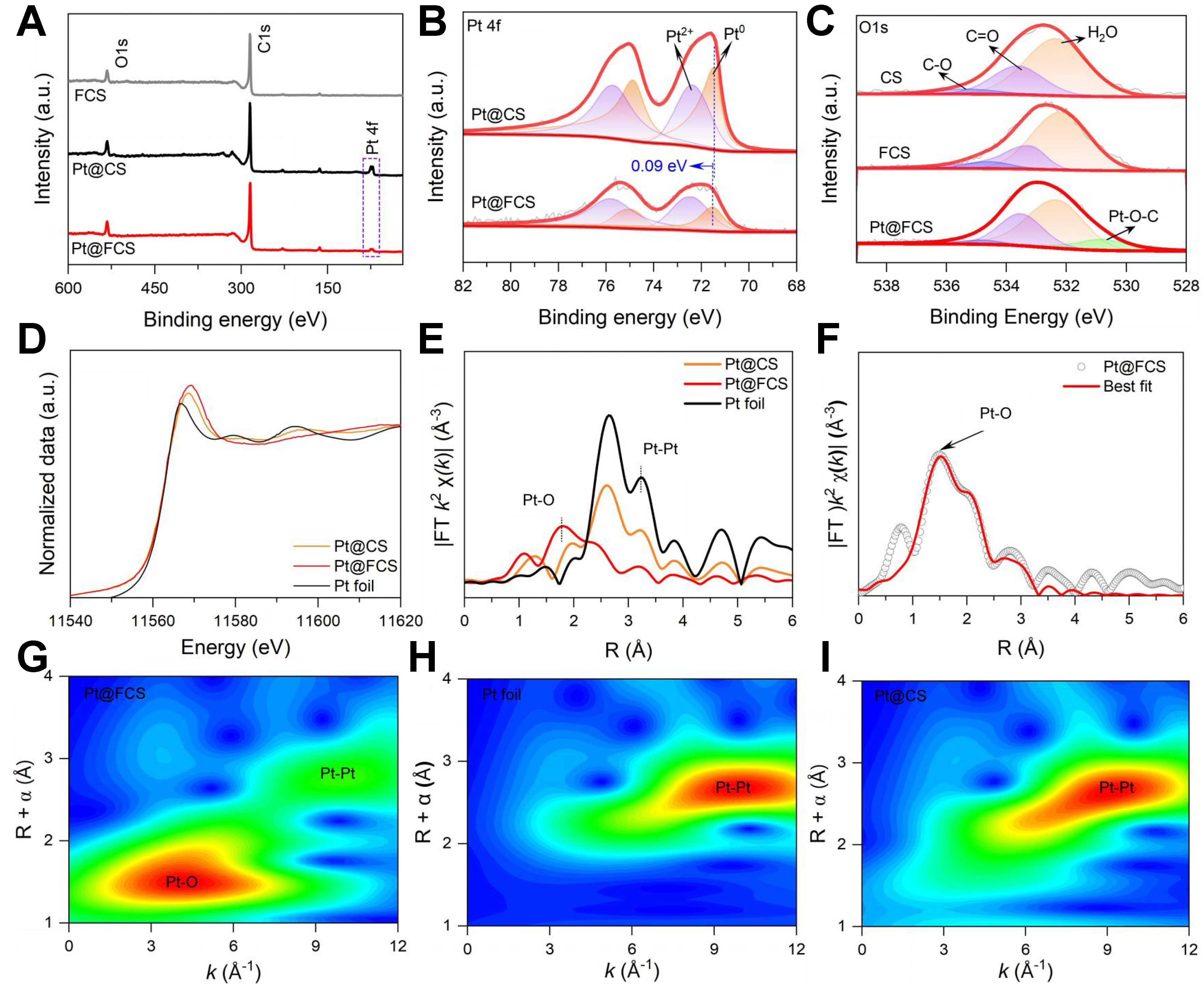
Figure 3. (A) XPS survey spectra of FCS, Pt@CS, and Pt@FCS; (B) High-resolution Pt 4f spectra highlighting the distinct electronic states of Pt species on Pt@CS and Pt@FCS; (C) O 1s spectra of CS, FCS, and Pt@FCS; (D) Pt L3-edge XANES spectra of Pt foil, Pt@CS, and Pt@FCS; (E) FT-EXAFS spectra illustrating the distinct first-shell coordination environments in Pt@CS and Pt@FCS; (F) EXAFS fitting of Pt@FCS; (G-I) WT contour plots of Pt@FCS, Pt foil, and Pt@CS. XPS: X-ray photoelectron spectroscopy; FCS: functionalized carbon support; CS: carbon support; XANES: X-ray absorption near edge structure; FT-EXAFS: Fourier transform extended X-ray absorption fine structure; WT: wavelet transform.
The chemical state and local coordination environment of Pt species were investigated by Pt L3-edge XAFS analysis. As shown in Figure 3D, the XANES spectra reveal a higher white-line intensity for Pt@FCS compared to both Pt foil and Pt@CS, indicating a higher oxidation state. This feature reflects electron depletion at Pt due to strong Pt-O interaction within the FCS matrix[47]. The k3-weighted EXAFS (Figure 3E, see k-space signal in Supplementary Figure 12) reveals a dominant Pt-O peak at ~1.9 Å, confirming that Pt species are stabilized mainly through coordination with O atoms during functionalization[48,49]. In contrast, Pt@CS and Pt foil display an intense peak at ~2.8 Å, characteristic of metallic Pt-Pt bonding. A weak Pt-Pt contribution at ~2.8 Å in Pt@FCS suggests the coexistence of SAs with a small number of NPs, in accordance with the HAADF-STEM observations. Quantitative EXAFS fitting shows that the first coordination shell of Pt in Pt@FCS consists of two O atoms with a fitted bond length of 1.90 Å [Figure 3F and Supplementary Table 3], further validating the Pt-O anchoring environment. Wavelet transform (WT) analysis [Figure 3G-I] further elucidates the local coordination environment by resolving the backscattering contributions in k space. For Pt@CS, the first-shell WT intensity is centered at k ≈ 9.3 Å-1, matching that of Pt foil, confirming that Pt engages in heavy-atom Pt-Pt coordination. This result validates the formation of large Pt particles on the unfunctionalized CS matrix. On the other hand, Pt@FCS exhibits its first-shell WT maximum at k ≈
To achieve maximized HER performance, we systematically tuned the Joule-heating parameters (including heating temperatures and pulse numbers) and the Pt impregnation concentration. For Pt@FCS, specifically, we further optimized the acid-functionalization conditions (see Experimental Section). We identify that a Pt precursor concentration of 0.4 mM, combined with Joule heating at 800 °C for 10 pulses, functionalized with 30 mol% HNO3, yields the optimal catalytic performance [Supplementary Figures 13 and 14]. Figure 4A shows the LSV curves of different electrodes. Among them, Pt@FCS exhibits the highest HER activity, achieving very low overpotentials of 33, 103, and 173 mV at current densities of 10, 50, and 100 mA cm-2, respectively. In contrast, Pt@CS exhibits higher overpotentials of 72, 212, and 356 mV at the same current densities [Figure 4B]. This remarkable enhancement demonstrates the catalytic advantage introduced by oxygen-rich surface functionalization, which strongly promotes the dispersion of Pt species and the formation of abundant SA sites.
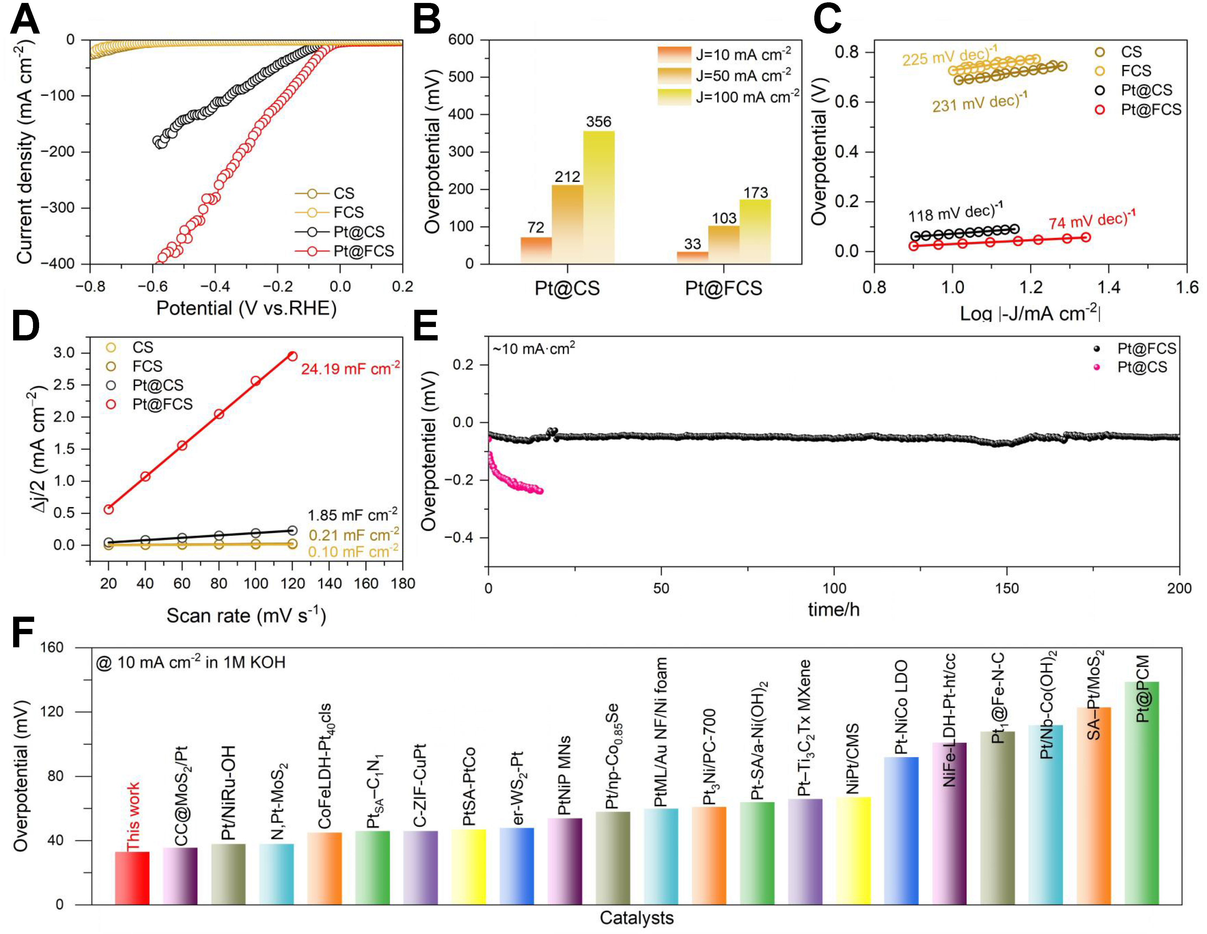
Figure 4. (A) LSV curves of CS, FCS, Pt@CS, and Pt@FCS; (B) overpotentials at 10 mA cm-2; (C) Tafel plots; (D) Cdl comparison extracted from CV measurements; (E) Chronopotentiometry stability test of Pt@FCS; (F) Comparison of the overpotential at 10 mA cm-2 Pt@FCS with state-of-the-art Pt-based HER electrocatalysts (references listed in Supplementary Table 4). LSV: Linear sweep voltammetry; CS: carbon support; FCS: functionalized carbon support; CV: cyclic voltammetry; HER: hydrogen evolution reaction; RHE: reversible hydrogen electrode.
Tafel analysis provides further insights into the HER kinetics. As shown in Figure 4C, Pt@FCS exhibits the smallest Tafel slope of 74 mV dec-1, which is considerably lower than that of Pt@CS (118 mV dec-1). This suggests faster hydrogen generation kinetics and confirms that our designed Pt SA/NP hybrid electrode follows a Volmer-Heyrovsky pathway with significantly improved charge-transfer efficiency[50]. To assess the availability of active sites, electrochemical Cdl was extracted from CV curves [Figure 4D and Supplementary Figure 15]. Pt@FCS exhibits a remarkably high Cdl of 24.19 mF cm-2, which is approximately 13 times that of Pt@CS (1.85 mF cm-2), 115 times that of FCS (0.21 mF cm-2), and 240 times that of CS (0.10 mF cm-2). This high Cdl value is consistent with the large population of exposed atomically dispersed Pt active sites. EIS further reveals the impact of acid-treated functionalization on electronic transport. As illustrated in Supplementary Figure 16, Pt@FCS displays the smallest Nyquist semicircle, indicating the lowest charge transfer resistance and the fastest electron transport, which collectively facilitate accelerated H2 evolution. The long-term stability of Pt@FCS and Pt@CS was evaluated by chronopotentiometry at 10 mA cm-2. As shown in Figure 4E, the Pt@FCS electrode maintains nearly constant potential over 200 h, with only a minimal increase. In stark contrast, Pt@CS exhibits a significant potential rise within just 20 h under identical conditions. This excellent durability highlights the strong anchoring effect of the functionalized carbon framework, which suppresses Pt migration and aggregation under operating conditions. To comparatively evaluate the elemental composition and Pt dissolution behavior of Pt@FCS before and after stability testing, XPS and ICP-OES analyses were conducted. As revealed by the survey spectra [Supplementary Figure 17], C, O, and Pt elements are clearly present in Pt@FCS both before and after 200 h of chronopotentiometry testing. High-resolution XPS analysis of the Pt 4f spectrum for Pt@FCS before and after 200 h of stability testing shows that Pt2+ remains the dominant oxidation state [Supplementary Figure 18]. Quantitative ICP-OES analysis reveals that the Pt loading in Pt@FCS decreases slightly to 0.28 wt.% after 200 h of continuous testing, corresponding to a minimal reduction of only ~0.01 wt.% [Supplementary Table 2]. This result indicates that the Pt species retain their oxidized state characteristic of Pt-O-C coordination, implying that the atomic dispersion is largely preserved even after prolonged operation. Additionally, to quantitatively evaluate the reproducibility of this process, we independently prepared five batches of Pt@FCS electrodes using identical optimized parameters. As shown in Supplementary Figure 19, the LSV curves of the five batches are nearly perfectly overlapped in 1 M KOH electrolyte. The average overpotential at
DFT calculations were performed to theoretically elucidate the superior alkaline HER activity of the designed Pt SA/NP hybrid catalyst. Based on the experiment results, we constructed three models with isolated Pt SA (PtSA), Pt NP (PtNP), and the hybrid (PtSA + PtNP) loaded on a single-layer graphene substrate [Supplementary Figure 21]. The calculation results indicate that water primarily adsorbs on the PtNP sites within the (PtSA + PtNP) hybrid structure, dissociating into H* and OH* intermediates. To elucidate the preferential adsorption sites for OH* and H* species after water dissociation, we systematically calculated their corresponding adsorption energies on each distinct active-site configuration. The PtNP sites in the hybrid (PtSA + PtNP) model exhibit a strongly exergonic OH* adsorption free energy (-0.596 eV), which is much stronger than that on the PtNP sites in (PtSA + PtNP) (-0.08 eV). So, a stronger OH* adsorption capability is expected on the PtSA sites around PtNP [Figure 5A]. These results demonstrate that the PtSA site promotes the transfer of OH* and exposes the PtNP active sites for water adsorption and subsequent dissociation when PtSA and PtNP coexist. As illustrated in Figure 5B, the PtNP sites within the hybrid (PtSA + PtNP) model exhibit a near-optimal Gibbs free energy of hydrogen adsorption (ΔGH*) of -0.18 eV, which is the closest value to the thermoneutral benchmark among all investigated configurations, demonstrating their superior capability for promoting the HER. In summary, these results establish a synergistic mechanism, where Pt NPs in the SA/NP hybrid electrode primarily drive water dissociation and H2 desorption, while the nearby Pt SAs critically enhance the active site utilization efficiency [Figure 5C].
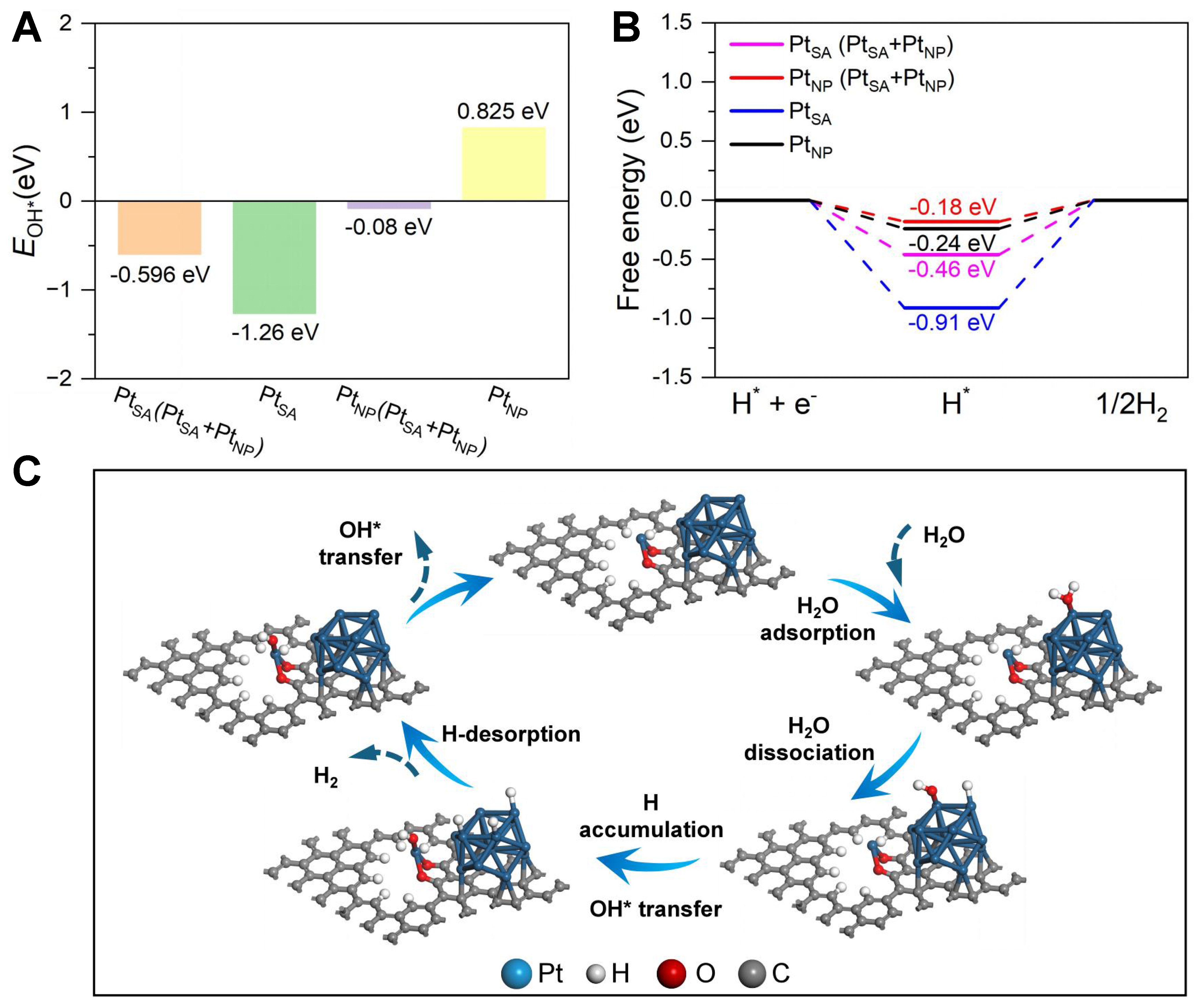
Figure 5. (A) Calculated OH* adsorption free energies on PtSA and PtNP sites within different constructed models; (B) The calculated free energy diagrams of H adsorption on different active sites; (C) Schematic illustration of the synergistic mechanism of Pt SA/NP hybrid electrode. SA: Single atom; NP: nanoparticle.
CONCLUSIONS
In summary, we have developed a novel strategy that combines 3D-printed hydrogel templating with ultrafast pulsed Joule heating to construct HER electrodes with dual active sites comprising Pt SAs and NPs. Derived from amorphous alloys, the 6M-TTP topological scaffold provides hierarchical porosity for improved mass transport and enables uniform stress distribution. These features collectively enhance the structural integrity and long-term stability of the integrated electrode. By integrating additive manufacturing with ultrafast Joule heating, we establish a seamless “macro-to-atomic” fabrication route that directly produces binder-free electrodes, avoiding the interfacial resistance and active site burial commonly associated with conventional slurry coating. Mechanistically, Pt NPs serve as the primary sites for water dissociation, while adjacent Pt SAs facilitate OH* transfer, creating a synergistic effect that accelerates alkaline HER kinetics. This work offers a versatile platform for designing high-performance, atom-efficient integrated electrodes for next-generation energy conversion technologies.
DECLARATIONS
Authors’ contributions
Investigation, methodology, data collection and analysis, writing - original draft: Jiao, C.
Writing - review and editing, visualization, validation: Zhu, Y.
Investigation, methodology: Liu, W.
Writing - review and editing, funding acquisition, conceptualization: Zhu, H.
Resources, data collection and analysis: Yu, R.
Resources, writing - review and editing, validation: Zhang, S.
Data collection and analysis: Xue, F.; Yao, Z.; Zhang, W.; Huang, J.
Writing - review and editing: Yu, F.
Writing - review and editing, Visualization: Liu, W. D.
Supervision, funding acquisition, writing - review and editing: Lan, S.
Availability of data and materials
The data that support the findings of this study are available from the corresponding author upon reasonable request.
AI and AI-assisted tools statement
Not applicable.
Financial support and sponsorship
This work was financially supported by the National Natural Science Foundation of China (Grant Nos. 22275089, 52573263, 52222104, 12261160364, 22502086), the Basic Research Program of Jiangsu (Nos. BK20253026, BK20251464), the Fundamental Research Funds for the Central Universities (No. 30925020216), and the Excellent Team of Qinglan Project in Jiangsu Province. We thank the BL13SSW beamline at the Shanghai Synchrotron Radiation Facility (https://cstr.cn/31124.02.SSRF.BL13SSW) for the XAFS experiments support.
Conflicts of interest
All authors declared that there are no conflicts of interest.
Ethical approval and consent to participate
Not applicable.
Consent for publication
Not applicable.
Copyright
© The Author(s) 2026.
Supplementary Materials
REFERENCES
1. Han, S.; Yun, Q.; Tu, S.; Zhu, L.; Cao, W.; Lu, Q. Metallic ruthenium-based nanomaterials for electrocatalytic and photocatalytic hydrogen evolution. J. Mater. Chem. A. 2019, 7, 24691-714.
2. Wang, T.; Cao, X.; Jiao, L. MOFs-derived carbon-based metal catalysts for energy-related electrocatalysis. Small 2021, 17, e2004398.
3. Zhu, X.; Huang, W.; Tan, L.; et al. Ultrafast synthesis of tetragonal-distorted FeCoNiCuCr high-entropy alloy nanoparticles for enhanced OER performance. Chin. Chem. Lett. 2026, 37, 110852.
4. Cheng, N.; Ren, L.; Xu, X.; Du, Y.; Dou, S. X. Recent development of zeolitic imidazolate frameworks (ZIFs) derived porous carbon based materials as electrocatalysts. Adv. Energy. Mater. 2018, 8, 1801257.
5. Radwan, A.; Jin, H.; He, D.; Mu, S. Design engineering, synthesis protocols, and energy applications of MOF-derived electrocatalysts. Nanomicro. Lett. 2021, 13, 132.
6. Shin, C.; Yu, T. H.; Lee, H.; et al. Ru-loaded pyrrolic-N-doped extensively graphitized porous carbon for high performance electrochemical hydrogen evolution. Appl. Catal. B. Environ. 2023, 334, 122829.
7. Vijayapradeep, S.; Logeshwaran, N.; Ramakrishnan, S.; et al. Novel Pt-carbon core–shell decorated hierarchical CoMo2S4 as efficient electrocatalysts for alkaline/seawater hydrogen evolution reaction. Chem. Eng. J. 2023, 473, 145348.
8. Tian, B.; Gao, W.; Ning, X.; Wu, Y.; Lu, G. Enhancing water splitting activity by protecting hydrogen evolution activity site from poisoning of oxygen species. Appl. Catal. B. Environ. 2019, 249, 138-46.
9. Yin, H.; Zhao, S.; Zhao, K.; et al. Ultrathin platinum nanowires grown on single-layered nickel hydroxide with high hydrogen evolution activity. Nat. Commun. 2015, 6, 6430.
10. Yan, Q. Q.; Wu, D. X.; Chu, S. Q.; et al. Reversing the charge transfer between platinum and sulfur-doped carbon support for electrocatalytic hydrogen evolution. Nat. Commun. 2019, 10, 4977.
11. Yang, M.; Jiao, L.; Dong, H.; et al. Conversion of bimetallic MOF to Ru-doped Cu electrocatalysts for efficient hydrogen evolution in alkaline media. Sci. Bull. 2021, 66, 257-64.
12. Li, L.; Qiu, H.; Zhu, Y.; et al. Atomic ruthenium modification of nickel-cobalt alloy for enhanced alkaline hydrogen evolution. Appl. Catal. B. Environ. 2023, 331, 122710.
13. Wang, M.; Feng, C.; Mi, W.; et al. Defect‐induced electron redistribution between Pt‐N3S1 single atomic sites and Pt clusters for synergistic electrocatalytic hydrogen production with ultra‐high mass activity. Adv. Funct. Mater. 2024, 34, 2309474.
14. Qiao, B.; Wang, A.; Yang, X.; et al. Single-atom catalysis of CO oxidation using Pt1/FeOx. Nat. Chem. 2011, 3, 634-41.
15. Sun, Y.; Lin, J.; Yang, W.; et al. Unraveling the multifunctional sites of Ag single-atom and nanoparticles confined within carbon nitride nanotubes for synergistic photocatalytic hydrogen evolution. Small 2025, 21, e2408655.
16. Luo, T.; Huang, J.; Hu, Y.; et al. Fullerene lattice‐confined Ru nanoparticles and single atoms synergistically boost electrocatalytic hydrogen evolution reaction. Adv. Funct. Mater. 2023, 33, 2213058.
17. Chang, Y. H.; Tseng, I. H.; Pourzolfaghar, H.; Lin, S. H.; Li, Y. Y. Atomic engineering of bifunctional core-shell catalysts with dual single-atom and cobalt nanoparticles for boosting ORR and OER kinetics in Zn-air batteries. Small 2025, 21, e06084.
18. Miao, H.; Zhang, D.; Shi, Y.; et al. Ultrasmall noble metal doped Ru2P@Ru/CNT as high-performance hydrogen evolution catalysts. ACS. Sustainable. Chem. Eng. 2021, 9, 15063-71.
19. Emana, B. B.; Bulge, T. B. Integrated electrodes for the nutrient removal from municipal wastewater using electrocoagulation technology. Sci. Rep. 2025, 15, 28244.
20. Chen, Y.; Qian, W.; Razansky, D.; Yu, X.; Qian, C. WISDEM: a hybrid wireless integrated sensing detector for simultaneous EEG and MRI. Nat. Methods. 2025, 22, 1944-53.
21. Brown, M. A.; Zappitelli, K. M.; Singh, L.; et al. Direct laser writing of 3D electrodes on flexible substrates. Nat. Commun. 2023, 14, 3610.
22. Scheideler, W. J.; Im, J. Recent advances in 3D printed electrodes - bridging the nano to mesoscale. Adv. Sci. 2025, 12, e2411951.
23. Ma, S.; Bai, W.; Xiong, D.; et al. Additive manufacturing of micro-architected copper based on an ion-exchangeable hydrogel. Angew. Chem. Int. Ed. Engl. 2024, 63, e202405135.
24. Saccone, M. A.; Gallivan, R. A.; Narita, K.; Yee, D. W.; Greer, J. R. Additive manufacturing of micro-architected metals via hydrogel infusion. Nature 2022, 612, 685-90.
25. Yao, Y.; Huang, Z.; Xie, P.; et al. High temperature shockwave stabilized single atoms. Nat. Nanotechnol. 2019, 14, 851-7.
26. Hussain, M. I.; Xia, M.; Ren, X.; Shen, Z.; Jamil, M.; Ge, C. Recent advances in photopolymerization 3D printing of alumina-ceramic. Prog. Nat. Scie. Mater. Int. 2025, 35, 1-30.
27. Luo, M.; Zhao, Z.; Zhang, Y.; et al. PdMo bimetallene for oxygen reduction catalysis. Nature 2019, 574, 81-5.
28. Ravel, B.; Newville, M. ATHENA, ARTEMIS, HEPHAESTUS: data analysis for X-ray absorption spectroscopy using IFEFFIT. J. Synchrotron. Radiat. 2005, 12, 537-41.
29. Anantharaj, S.; Sagayaraj, P. J. J.; Yesupatham, M. S.; et al. The reference electrode dilemma in energy conversion electrocatalysis: “right vs. okay vs. wrong”. J. Mater. Chem. A. 2023, 11, 17699-709.
30. Kresse, G.; Furthmüller, J. Efficient iterative schemes for ab initio total-energy calculations using a plane-wave basis set. Phys. Rev. B. Condens. Matter. 1996, 54, 11169-86.
31. Kresse, G.; Hafner, J. Ab initio molecular dynamics for liquid metals. Phys. Rev. B. Condens. Matter. 1993, 47, 558-61.
32. Hammer, B.; Hansen, L. B.; Nørskov, J. K. Improved adsorption energetics within density-functional theory using revised Perdew-Burke-Ernzerhof functionals. Phys. Rev. B. 1999, 59, 7413-21.
33. Ma, M.; Xu, J.; Wang, H.; et al. Multi-interfacial engineering of hierarchical CoNi2S4/WS2/Co9S8 hybrid frameworks for robust all-pH electrocatalytic hydrogen evolution. Appl. Catal. B. Environ. 2021, 297, 120455.
34. Nørskov, J. K.; Bligaard, T.; Logadottir, A.; et al. Trends in the exchange current for hydrogen evolution. J. Electrochem. Soc. 2005, 152, J23.
35. El Nemr, A.; Aboughaly, R. M.; El Sikaily, A.; Masoud, M. S.; Ramadan, M. S.; Ragab, S. Microporous-activated carbons of type I adsorption isotherm derived from sugarcane bagasse impregnated with zinc chloride. Carbon. Lett. 2022, 32, 229-49.
36. Tao, L.; Wang, Y.; Zou, Y.; et al. Charge transfer modulated activity of carbon‐based electrocatalysts. Adv. Energy. Mater. 2020, 10, 1901227.
37. Wang, M.; Zheng, X.; Qin, D.; et al. Atomically dispersed CoN3C1-TeN1C3 diatomic sites anchored in N-doped carbon as efficient bifunctional catalyst for synergistic electrocatalytic hydrogen evolution and oxygen reduction. Small 2022, 18, e2201974.
38. Gong, X.; Li, D.; Zhang, Q.; et al. Cobalt single atoms supported on monolithic carbon with a hollow-on-hollow architecture for efficient transfer hydrogenations. Nano. Res. 2023, 16, 11358-65.
39. Wu, N.; Zhao, Z.; Zhang, Y.; et al. Revealing the fast reaction kinetics and interfacial behaviors of CuFeS2 hollow nanorods for durable and high-rate sodium storage. J. Colloid. Interface. Sci. 2025, 679, 990-1000.
40. Ma, X.; Guo, C.; Xiang, J.; et al. Synthesis and applications of biomass-derived electrocatalysts in water electrolysis. Int. J. Hydrogen. Energy. 2024, 60, 845-66.
41. Tao, Y.; Endo, M.; Kaneko, K. Hydrophilicity-controlled carbon aerogels with high mesoporosity. J. Am. Chem. Soc. 2009, 131, 904-5.
42. Liang, L.; Jin, H.; Zhou, H.; et al. Cobalt single atom site isolated Pt nanoparticles for efficient ORR and HER in acid media. Nano. Energy. 2021, 88, 106221.
43. Feng, Y.; Li, Z.; Li, S.; Yang, M.; Ma, R.; Wang, J. One stone two birds: vanadium doping as dual roles in self-reduced Pt clusters and accelerated water splitting. J. Energy. Chem. 2022, 66, 493-501.
44. Feng, Y.; Ma, R.; Wang, M.; et al. Crystallinity effect of NiFe LDH on the growth of Pt nanoparticles and hydrogen evolution performance. J. Phys. Chem. Lett. 2021, 12, 7221-8.
45. Yang, M.; Liu, J.; Lee, S.; et al. A common single-site Pt(II)-O(OH)x-species stabilized by sodium on "active" and "inert" supports catalyzes the water-gas shift reaction. J. Am. Chem. Soc. 2015, 137, 3470-3.
46. Jiang, Y.; Deng, Y.; Fu, J.; et al. Interpenetrating triphase cobalt‐based nanocomposites as efficient bifunctional oxygen electrocatalysts for long‐lasting rechargeable Zn–air batteries. Adv. Energy. Mater. 2018, 8, 1702900.
47. Shen, R.; Chen, W.; Peng, Q.; et al. High-concentration single atomic Pt sites on hollow CuSx for selective O2 reduction to H2O2 in acid solution. Chem 2019, 5, 2099-110.
48. Ren, Y.; Tang, Y.; Zhang, L.; et al. Unraveling the coordination structure-performance relationship in Pt1/Fe2O3 single-atom catalyst. Nat. Commun. 2019, 10, 4500.
49. Zhu, Y.; Luo, Y.; Yao, J.; et al. Atomically dispersed Pt-O coordination boosts highly active and durable acidic hydrogen evolution reaction. Chem. Eng. J. 2022, 440, 135957.
Cite This Article
How to Cite
Download Citation
Export Citation File:
Type of Import
Tips on Downloading Citation
Citation Manager File Format
Type of Import
Direct Import: When the Direct Import option is selected (the default state), a dialogue box will give you the option to Save or Open the downloaded citation data. Choosing Open will either launch your citation manager or give you a choice of applications with which to use the metadata. The Save option saves the file locally for later use.
Indirect Import: When the Indirect Import option is selected, the metadata is displayed and may be copied and pasted as needed.
About This Article
Copyright

Data & Comments
Data
0


Comments
Comments must be written in English. Spam, offensive content, impersonation, and private information will not be permitted. If any comment is reported and identified as inappropriate content by OAE staff, the comment will be removed without notice. If you have any queries or need any help, please contact us at [email protected].