


fig8
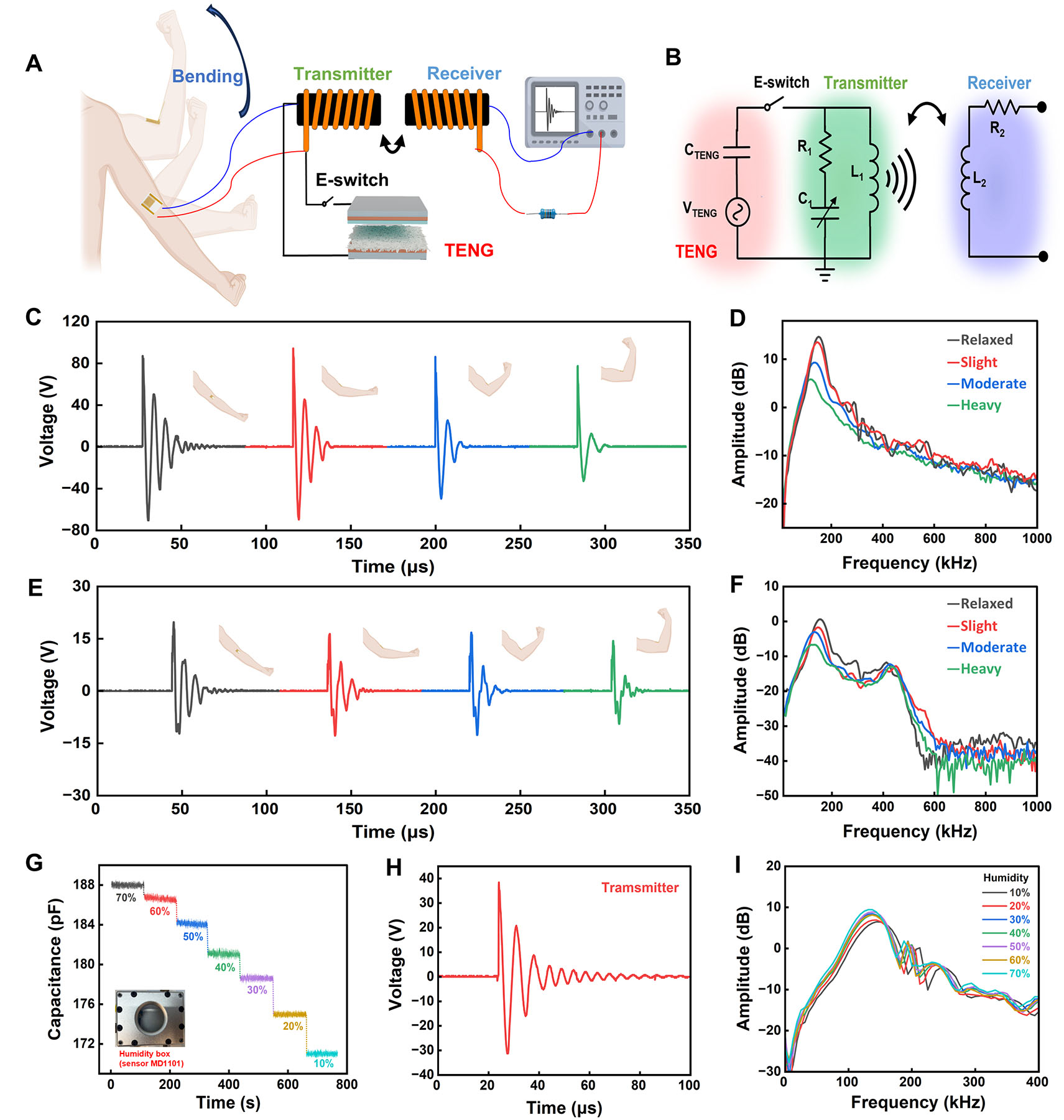
Figure 8. Self-powered wireless sensing system. (A) System overview. (The arm bending illustration was created with BioRender; Chen, C. (2025) https://BioRender.com/z63tmpw). (B) Circuit diagram. (C) Signals of the transmitter side at different arm bending angles. (D) Corresponding transmitted signals after FFT analysis. (E) Corresponding signals of the receiver side. (F) Corresponding received signals after FFT analysis. (G) Capacitance variation of the capacitive sensor with humidity. (The inset is the box with the humidity sensor.) (H) One transmitted signal with encoded humidity information. (I) Received signals containing humidity information after FFT.


