Download PDF
Article  |  Open Access  |  27 Aug 2025

A high capacity V$$_4$$C$$_3$$T$$_z$$ MXene electrode: expanding the limits of stable electrochemical windows using a highly concentrated LiBr/H$$_2$$O electrolyte

Views: 120 |  Downloads: 1 |  Cited:  0
Energy Mater. 2025, 5, 500143.
10.20517/energymater.2024.280 |  © The Author(s) 2025.
Author Information
Article Notes
Cite This Article

Abstract

The use of highly concentrated electrolytes to enlarge the operational electrochemical window of MXenes is a strategy to enhance their energy density. Here, we demonstrate that V$$ _4 $$C$$ _3 $$T$$ _z $$ can operate in a -0.7 to 0.8 V vs. Ag electrochemical window in a 17.5 m LiBr/H$$ _2 $$O electrolyte achieving a high capacity/capacitance of 237.1 C g-1/745.5 C cm-3/158 F g-1, electrode energy density of 49.4 Wh kg-1/155.3 mWh cm-3, and a high cycling stability up to 10, 000 cycles. This performance is superior to previously reported MXenes, including Ti$$ _3 $$C$$ _2 $$T$$ _z $$ and Ti$$ _2 $$CT$$ _z $$ tested in water-in-salt electrolytes and hydrate melts. We demonstrate the key role of electrolyte concentration in maximizing the electrochemically stable window. Electrolyte formulations in the low-concentration (5 m, 7.5 m and 10 m) and high-concentration (12.5 m, 15 m, 17.5 m, and 19 m) regimes were investigated. The best performance balance of capacity, capacity retention, Coulombic efficiency and cycling stability was achieved in the 17.5 m electrolyte. Electrochemical methods showed that this electrolyte formulation enabled the stabilization of the electrode against the hydrogen evolution reaction and oxidation processes at negative and positive potentials vs. Ag, respectively, where an interfacial film at the electrode-electrolyte interface, confirmed by electrochemical impedance spectroscopy, played a key role. Physical properties of the electrolyte were correlated to electrode performance. Importantly, this optimum performance was achieved without reaching the electrolyte concentration at the LiBr solubility limit at room temperature (19 m), which undermines rate performance and brings other operational issues.

Keywords

V4C3Tz MXene, water-in-salt electrolytes, LiBr, electrochemical window, enhanced charge storage, enhanced energy density

INTRODUCTION

The development of more efficient, sustainable and cost-effective energy storage devices is one of the top priorities in our society enabling the migration to renewable energies and supplying for the energy storage needs of a growing market of a range of applications including wearable electronics. The greatest challenge is to develop energy storage devices with high energy density and power density. Supercapacitors are high power density devices, as compared to batteries, but supply a comparatively lower energy density. Hence, enhancing energy density of supercapacitors is a current focus of intensive research.

MXenes have emerged as excellent material for supercapacitor applications[1]. MXenes, M$$ _{n+1} $$X$$ _n $$T$$ _z $$, are derived from M$$ _{n+1} $$AX$$ _n $$ precursors (termed MAX), where n$$ = $$ 1-4, M is an early transition metal (Ti, V, Mo, Ta, Nb, etc.), A is an element of the group IIIA or IVA (e.g., Al, Ga, Si, Ge, etc.), X is C and/or N and T$$ _z $$ describes surface chemical functionalities (-O, -F and -OH, -Cl groups and others)[2,3]. To date, more than 30 stoichiometric MXenes have been synthesized[3].

MXenes have demonstrated a high-rate performance in aqueous electrolytes of typically 1 M concentration. However, an area of improvement is the enlarging of typically negative electrochemical windows (EWs) vs. open circuit potential (OCP) to improve energy density. Particularly, Ti$$ _3 $$C$$ _2 $$T$$ _z $$ has been investigated in various aqueous electrolytes consisting of monovalent and multivalent cations H$$ ^{+} $$, Li$$ ^{+} $$, Na$$ ^{+} $$, K$$ ^{+} $$, Mg$$ ^{+2} $$, Al$$ ^{+3} $$[4,5]. Equally, other MXenes have been investigated in a variety of aqueous electrolytes: Ti$$ _2 $$CT$$ _z $$[6], V$$ _2 $$CT$$ _z $$[7,8], Mo$$ _2 $$CT$$ _z $$[9], Mo$$ _2 $$TiC$$ _2 $$T$$ _z $$[10], Mo$$ _x $$V$$ _{4-x} $$C$$ _3 $$[11] and Nb$$ _{4} $$C$$ _3 $$T$$ _z $$[12]. A typical EW, illustrated for the case of Ti$$ _3 $$C$$ _2 $$T$$ _z $$ in 1 M H$$ _2 $$SO$$ _4 $$, is -0.35 to 0.2 V vs. Ag/AgCl[5], limited by the hydrogen evolution reaction (HER) at negative potentials and by oxidation of the MXene at positive potentials[4]. This limits the capacity achieved in this 0.55 V EW. Recently, we have reported the performance of V$$ _4 $$C$$ _3 $$T$$ _z $$ in 3 M H$$ _2 $$SO$$ _4 $$ in a larger -0.35 to 0.4 Vvs. Ag/AgCl (0.75 V) EW[13], which achieved a larger capacity than the Ti$$ _3 $$C$$ _2 $$T$$ _z $$ in 1 M H$$ _2 $$SO$$ _4 $$[5]. The negative limit of the electrochemically stable window can be extended further in neutral electrolytes but at the expense of a lower energy density, linked to a lower ionic conductivity, as compared to acidic electrolytes, and energy storage mechanisms limited to double-layer capacitance[4,14]. Hence, an electrolyte that overcomes the limits imposed by HER at negative potentials, and limiting MXene oxidation processes or the oxygen evolution reaction (OER) at positive potentials, while providing high energy density would be ideal to exploit the full storage potential of MXenes.

Recently, water-in-salt electrolytes (WISEs) have emerged as a suitable alternative to enlarge the electrochemically stable windows, hence energy density, of MXene-based supercapacitors, overcoming the limitations imposed by standard aqueous electrolytes. WISEs are highly concentrated electrolytes (HCEs) where the salt outnumbers the water in weight and volume[15,16], and very few water molecules are free to form hydrogen bonds[17]. Unlike their salt-in-water counterpart, in WISEs, cation-anion interactions such as contact ion pairs (CIPs) and aggregated cation-anion pairs (ACAPs) dominate over ion-solvent interactions leading to unusual physicochemical properties[15,18]. The advantages of WISEs in energy storage were first visualized and utilized in battery applications to enlarge the electrochemically stable windows, where both HER and OER shifted to lower and higher potentials, respectively[15]. HER shifted to lower potentials as a result of a preferential reduction reaction of anions in cation-anion adducts (formed as a result of the very high concentration of salt) over water molecules[15]. This reduction reaction resulted in the formation of a passivation layer that eventually suppressed HER[15]. The shift of OER to positive potentials has been explained by several works. When coordinated with cations such as Li$$ ^+ $$, a Lewis acid, a water molecule donates its one electron from a lone pair in the oxygen, which lowers its highest occupied molecular orbital (HOMO) raising its oxidation potential[17,19,20]. In addition, the activity of water molecules is reduced due to the coordination with cations, and the formation of an inner Helmholtz layer populated with anions[21,22]. As an emerging field, newer studies on WISE structure lead to new criteria for WISE definition[23]. As found in this work using molecular dynamics simulations (Section {"Electrolyte formulations"}), a high-concentration electrolyte does not necessarily lead to the electrolyte structure and properties described for known WISEs. Thus, emphasizing the need for careful consideration before asserting HCEs as WISEs.

Another category of electrolytes of even higher salt concentration is hydrate melts, in which all the water molecules are coordinated with cations or CIPs and no water molecules are free to form hydrogen bonds[17]. Especially designed hydrate melts favor water solvation of cations disabling the formation of CIPs[17]. A disadvantage of WISEs and some hydrate melts is a substantial reduction of the reaction kinetics of energy storage process due to low ionic conductivity and high viscosity of such HCEs.

In the case of MXenes, WISEs have been used to enlarge the negative limit of electrochemically stable windows, while being paired with electrodes operating at positive potentials for the achievement of full cells. Ti$$ _3 $$C$$ _2 $$T$$ _z $$ has been used in a -0.1 to -1.6 V vs. Hg/Hg$$ _2 $$Cl$$ _2 $$ EW in a 21 m potassium acetate (KAcO) electrolyte, while pairing with a MnO$$ _2 $$ in a full cell that achieved a 2.2 voltage window[14]. More recently, Ti$$ _3 $$C$$ _2 $$T$$ _z $$ was tested in 19.8 m LiCl, 19.2 m LiBr and 15 m lithium bis(trifluoromethane sulfonyl) imide (LiTFSI) that achieved an enlargement of the electrochemically stable window not only at the negative limit to -0.8 V vs. Ag (for 19.8 m LiCl) but also to the positive limit to 0.8 V vs. Ag[24,25]. The latter is remarkable, first, because it implies that WISEs enable new energy storage processes in positive EWs (vs. OCP) of the MXenes, and, second, this is possible because, in the presence of WISEs, the MXene degradation induced by electrochemical processes at these potentials is presumably inhibited[24,25]. The newly elucidated energy storage processes were reported to consist of "desolvation-free" cation (de-)intercalation (three molecules of water per cation) that had a degree of ion-diffusion and charge transfer resistance, and thus, slower as compared to partially desolvated ion intercalation pseudocapacitive processes having place at the negative EW (vs. OCP)[24]. Other works considered Ti$$ _3 $$C$$ _2 $$T$$ _z $$, Ti$$ _2 $$C$$ _2 $$T$$ _z $$ and Nb$$ _2 $$CT$$ _z $$ in 21 m LiTFSI and hydrate melts[26,27]. Importantly, these works established that charge storage at the MXene interlayer space is dominated by CIP dissociation processes[27] and a high charge density of solvated cations[26]. Nevertheless, the charge storage properties of MXenes of the type M$$ _{4} $$X$$ _3 $$T$$ _z $$ have not yet been investigated in HCEs.

Herein, we investigate the charge storage processes of V$$ _4 $$C$$ _3 $$T$$ _z $$ MXene in a LiBr/H$$ _2 $$O electrolyte with the aim of establishing the optimum electrolyte formulation that enables maximum charge storage and best rate performance and cycling stability in the largest possible electrochemically stable potential window. We address this aim by utilizing a key combination of a range of electrochemicals, including electrochemical impedance spectroscopy (EIS), and electrolyte physical properties studies. We unveiled the key role of electrolyte concentration, investigated in a range of concentrations from 5 m to 19 m, and electrolyte physical properties in charge storage processes and performance. We established the optimum electrolyte concentration (17.5 m) and correlated physical properties that led to the best energy storage performance in terms of capacity, capacity retention and cycling stability. Unlike previous reports, we concluded that the optimum performance can be achieved without using electrolyte formulations in the salt solubility limit (19 m), which brings performance and operational disadvantages. The capacity, capacitance and energy density here achieved for the V$$ _4 $$C$$ _3 $$T$$ _z $$/17.5 m LiBr/H$$ _2 $$O system are superior to other MXenes previously reported and investigated in WISEs and hydrate melts, attributed to the particular MXene chemistry and stoichiometry and careful tuning of electrolyte formulation. We report on the unique electrochemical processes enabled by the optimum electrolyte formulation, including the formation of an interfacial film at the electrode-electrolyte interface, and on ion transport processes (diffusion coefficients).

EXPERIMENTAL METHODS

Chemicals

Hydrofluoric acid (HF, 48 wt.$$ \% $$, 27.58 M), hydrochloric acid (HCl, 37 wt.$$ \% $$, 12.17 M), tetrabutylammonium hydroxide (TBAOH, 40 wt.$$ \% $$ in water), and LiBr ($$ > $$ 99%, Reagent plus) were acquired from Sigma Aldrich, Germany. Deionized (DI) water of 18.2 M$$ \Omega $$ cm resistivity was used for synthesis procedures and electrolyte preparation.

Synthesis of V$$ _4 $$AlC$$ _3 $$

As reported previously in[13]. Vanadium powder (99.5%, -325 mesh, Alfa Aesar), aluminum powder (99.5%, -325 mesh, Alfa Aesar), and graphite (99$$ \% $$, -325 mesh, Alfa Aesar) were mixed in a 4:1.5:3 atomic ratio (10 g in total). The precursors were balled-milled with 5 mm Yttria Stabilized Zirconia balls (2:1 ball: powder ratio) in plastic jars at 60 rpm for 18 h. The powder mixture was then transferred to alumina crucibles, which were placed into a high-temperature tube furnace (Carbolite Gero). Ultra-high purity Ar (99.999$$ \% $$) gas was continually flown (200 cm-3 min-1) through the furnace for 1 h prior to heating and during the entire annealing procedure. The furnace was heated to 1, 500 $$ ^{\circ} $$C at 3 $$ ^{\circ} $$C min-1, held for 2 h, and then cooled to room temperature at 3 $$ ^{\circ} $$C min-1. The resulting solid block product was milled using a drill press with a TiN-coated milling bit. The powders were then sieved through a 400 mesh sieve, producing powders with a particle size $$ < $$ 38 $$ \mu $$m. The powders were then washed with HCl 37 wt.$$ \% $$; 10 g of powder were added slowly to 20 ml of HCl 37 wt.$$ \% $$ and stirred overnight. Then the acid was removed by vacuum-assisted filtration while flushing water until the filtrated liquid had pH = 7. The powders were then dried in vacuum at room temperature.

Synthesis of etched V$$ _4 $$AlC$$ _3 $$

As reported previously in[13]. Prior to etching procedures, particle size selection was performed. Powder of particle size $$ < $$ 36 $$ \mu $$m was selected (using a 36 $$ \mu $$m sieve) for etching processes. For the etching reaction, a 50 mL (4 cm bottom diameter) polytetrafluoroethylene (PTFE) reaction vessel and a 3 cm long magnetic stir bar were used. A HF (12 ML): HCl (12 mL): H$$ _2 $$O (6 mL), for a total of 30 mL, acid mix was carefully placed in the reaction vessel. Then, 1 g of V$$ _4 $$AlC$$ _3 $$ was added in small portions over 20 min while stirring at 50 rpm. The reaction vessel was then closed with the screw top lid giving 70$$ \% $$ of the turns necessary to fully close (important to allow gas evolution). The reaction vessel was then immersed in a silicon oil bath maintained at 45 $$ ^{\circ} $$C with the level of oil up to the height of the reaction mix and magnetic stirring was set to 400 rpm. The reaction was performed for 7 d.

After etching, the reaction mixture was placed in conical centrifuge tubes (150 mL); DI water was added and centrifugation was done at 5, 000 rpm for 10 min. The acidic supernatant was collected with a pipette and discarded. This step was repeated until the supernatant reached pH 5-6. The etched powder was then further washed and collected by vacuum-assisted filtration, using polyvinylidene fluoride (PVDF) membrane filters (0.22 $$ \mu $$m pore size). DI water (500 mL) was continuously flushed, and then the powders were left to settle and dry over the membrane filter (for 3-5 min) prior to collection.

Delamination of etched V$$ _4 $$AlC$$ _3 $$

As reported previously in[13]. For delamination, the etched powder was added to 10 wt.$$ \% $$ TBAOH, in a 2:1 mol ratio of TBAOH: V$$ _4 $$C$$ _3 $$, and stirred at 350 rpm, at 35 $$ ^{\circ} $$C, for 17 h. Afterward, washing steps were carried out to retrieve the TBAOH. The TBAOH intercalated products were placed in conical centrifuge tubes (150 mL); DI water was added and centrifugation was done at 5, 000 rpm for 10 min. The top 70$$ \% $$-80$$ \% $$ volume was pipetted out. This step was repeated until achieving pH 7-8, usually three steps. Then, DI water was added; the product was vigorously shaken by hand for 10 min, followed by centrifugation at 3, 500 rpm for 30 min. The top 70$$ \% $$ volume was pipetted out and constituted the delaminated material. This step was repeated three times to obtain more fractions of delaminated product. The V$$ _4 $$C$$ _3 $$T$$ _x $$/H$$ _2 $$O suspensions of delaminated material were either immediately processed for film manufacture or stored. Storing of V$$ _4 $$C$$ _3 $$/H$$ _2 $$O suspensions was done in gas-washing bottles bubbling with Ar for 5 min, followed by closing under Ar pressure and storing at 5 $$ ^{\circ} $$C.

V$$ _4 $$C$$ _3 $$T$$ _z $$ film manufacture

As reported previously in[13]. Delaminated films were manufactured using vacuum-assisted filtration. A standard glass vacuum filtration system and a Celgard 3501 filter membrane (64 nm pore size) were used. To determine the suspension volume to filter to achieve a determined film thickness, calibration was necessary according to the concentration of the suspension. In general, to reduce concentration and facilitate faster filtration, as-produced suspensions were purified by a centrifugation step at 5, 000 rpm for 30 min and collection of the top 70$$ \% $$ volume. In general, films were obtained by filtering 20-30 mL of V$$ _4 $$C$$ _3 $$T$$ _z $$/H$$ _2 $$O purified suspension per film. The film/filter membrane stack was then collected and dried in a B-585 Büchi glass vacuum oven at room temperature for 5 h. The film was then separated from the membrane filter and its weight and thickness were measured. The films used here had a thickness of 4-8 $$ \mu $$m. Electrodes used for electrochemical testing had a 3 mm diameter. Generally, the films were stored in a glove box ($$ < $$ 0.1 ppm O$$ _2 $$, $$ < $$ 0.1 ppm H$$ _2 $$O).

Electrolyte preparation and property measurements

LiBr/water electrolytes of 5, 7.5, 10, 12.5, 15, 17.5 and 19 molal concentration were prepared at room temperature by adding the LiBr salt in small portions to DI water (25 mL) while magnetically stirring (100 rpm). Complete dissolution, especially in the most concentrated electrolytes, was ensured by stirring overnight. The recipients containing the electrolyte were maintained closed to avoid water evaporation caused by the highly exothermic dissolution.

The following observations are worth noting. In this work, we found the limit of solubility of LiBr in DI water to be 19.0 m and not 19.2 m, as previously reported[24,25]. Previous studies in LiBr aqueous solubility as a function of temperature state a theoretical equilibrium solubility of a 0.625 wt.$$ \% $$ (19.2 m) solution at $$ \approx $$ 23.3 $$ ^{\circ} $$C and 1 atm[28]. Any slight variation toward lower temperatures or increased concentration will lead to crystallization. Other reports state an equilibrium solubility of 0.625 wt.$$ \% $$ (19.2 m) solutions at 33.14 $$ ^{\circ} $$C and 0.6063 wt.$$ \% $$ (17.73 m) solutions at 24.29 $$ ^{\circ} $$C[29]. These discrepancies were attributed by authors of these works to the use of different methods of calculation and/or experimental determination[29]. Other factors such as purity of the salt and the water can make a difference in solubility at this limiting concentration.

Measurements of electrolyte viscosity and conductivity were done at 25 $$ ^{\circ} $$C. The viscosity was measured using an ARES G2 rheometer (TA Instruments) equipped with a stainless steel recessed (parallel cylinders) Couette Cell (Bob diameter of 18.596 mm and cup diameter 19.992 mm, loading gap of 100 mm). A volume of 2.12 mL of each electrolyte was measured and each sample was measured at least six times. Preconditioning tests were performed to determine the best shear rate for tests. Conductivity measurements were performed using a Seven2Go S7 (Metler Toledo) conductivity meter equipped with an InLab 738-ISM sensor with a 0.001 to 1 mS cm-1 resolution. Each sample was measured at least three times. Calibration of the instrument was done with standard samples prior to measurements.

Equipment

Centrifugation was performed using a centrifuge (Thermo Scientific Heraeus Multifuge X1R) equipped with a TX-400 rotor (16.8 cm radius). The relative centrifugal force (RCF), measured in gravity acceleration (g) units, is defined as

$$ RCF = 1.118 \times 10^{-5} \times S^{2} \times r $$

where S is the centrifugal rotational speed (rpm), and r is the radius of the rotor (cm). This formula should be used to convert the $$ S $$ cited in this work to RCF.

The mass of the powders was measured using a balance (Sartorius, Germany) with a 0.0001 $$ \pm $$ 0.00015 g readability. The mass of electrodes was measured using an ultramicrobalance (Mettler Toledo XPR2U) with a 0.0001 $$ \pm $$ 0.00015 mg readability. The thickness of film electrodes was measured with a HEIDENHAIN ND280 length gauge with a 0.0001 mm readability.

Materials characterization methods

Materials characterization was performed in our previous work[13]. Here, we describe briefly instrumentation. Scanning electron microscopy (SEM) was performed in a ZEISS Merlin (ZEISS, Germany) microscope equipped with a GEMINI II column and using the In Lens detector. Standard and high-resolution high angle annular dark field scanning transmission electron microscopy (HAADF-STEM) and electron-energy loss spectroscopy (EELS) were conducted using a double C$$ _s $$ corrected FEI Titan$$ ^3 $$ 60-300 (Linköping, Sweden), operated at 300 kV. EELS was performed using the embedded Gatan imaging filter (GIF) Quantum ERS. Further details on sample preparation and data analysis are given in our previous work[13].

X-ray diffraction (XRD) was performed in a STOE STADI P diffractometer with a Mo K$$ \alpha $$1 radiation source ($$ \lambda $$ = 0.7093 $$ \mathscr{B} $$, 50 kV, 40 mA), a Ge 111 monochromator and a MYTHEN 1D silicon strip detector. The samples were measured using a Debye-Scherrer geometry using glass capillaries. The data was acquired from 2$$ \theta $$ = 2 to 92$$ ^{\circ} $$ in 2$$ \theta $$ = 0.495$$ ^{\circ} $$ steps and acquisition of 1.98 min/step for a total measuring time of 6 h. Each measurement was done twice to ensure reproducibility. Further details on sample preparation and data analysis are given in our previous work[13].

Electrochemical methods

Electrochemical cell. Electrochemical tests were performed in 1/4 inch 3-electrode perfluoroalkoxy alkane (PFA) Swagelok cells using 6 mm diameter glassy carbon rods as current collectors. Cells were assembled using disc electrodes of V$$ _4 $$C$$ _3 $$ film as a working electrode, an overcapacitive carbon film as a counter electrode (5 mm diameter), an Ag as a pseudoreference electrode and a Celgard 3501 film (6 mm diameter) as a separator. LiBr/H$$ _2 $$O electrolytes of 5 to 19 m concentration were used. The manufacture of the overcapacitive carbon electrode has been reported in our previous work[13].

Electrochemical tests. Electrochemical tests were performed in a VMP300 (BioLogic) potentiostat using EC-Lab software. Cyclic voltammetry (CV) was the main technique used. The capacitance C (F) was calculated as:

$$ C^{+/-} = \frac{\Delta Q^{+/-}}{\Delta V} = \frac{\int I^{+/-} dt}{(V_2 - V_1)} $$

where anodic ($$ + $$) and cathodic ($$ - $$) charge Q$$ ^{+/-} $$ (C) were obtained by numerical integration of the corresponding I$$ ^{+/-} $$ currents of the cyclic voltammogram. V$$ _1 $$ and V$$ _2 $$ (V) are the potential window limits of the CV and t (s) is time. The Coulombic efficiency (CE) was calculated as (Q$$ ^{+} $$/Q$$ ^{-} $$) $$ \times $$ 100. Chronoamperograms (CAs) were recorded at different potentials vs. Ag, for 15-30 min for the study of the limits of stability of EWs.

Galvanostatic cycling with potential limitation (GCPL) was performed according to the potential limits established by CV and according to the electrolyte concentration. GCPL rate tests were performed at 0.25 to 10 A g-1 current rates. The CE from GCPL studies was calculated as (Q$$ _{charge} $$/Q$$ _{discharge} $$) $$ \times $$ 100.

Staircase potentio-EIS (SPEIS), a technique suitable for performing successive EIS measurements during a potential scan, was used to study ion transport processes[13]. SPEIS was performed in half-cell electrode setups using electrolytes of selected concentrations. The measurements were conducted along a CV scan following an OCP to V$$ _1 $$ to V$$ _2 $$ to OCP sequence. Polarization (holding DC potential) was done every 25 mV during 10 min before the performance of each EIS measurement. EIS was performed by applying a single sine alternate voltage of 10 mV amplitude (V$$ _{rms} $$ = 7.07 mV). Measurements were done in a 4 mHz to 250 kHz frequency range, reading ten points per decade (logarithmic scale) and averaging five measurements per read frequency point. A waiting period of p$$ _w $$ = 0.1(1/frequency) (s) was set before reading each frequency point.

Capacitance was calculated from EIS studies according to[30]:

$$ Z(\omega) = \frac{1}{j \omega C (\omega)} $$

where $$ \omega $$$$ = $$ 2$$ \pi $$f is the angular frequency with f$$ = $$ frequency (Hz) and j$$ = $$$$ \sqrt{-1} $$.

$$ C'(\omega) = \frac{-Z" (\omega)}{\omega |Z(\omega)|^{2}} $$

$$ C''(\omega) = \frac{Z' (\omega)}{\omega |Z(\omega)|^{2}} $$

where $$ |Z(\omega)| $$ is the magnitude of the impedance.

Results and discussion

Materials characterization

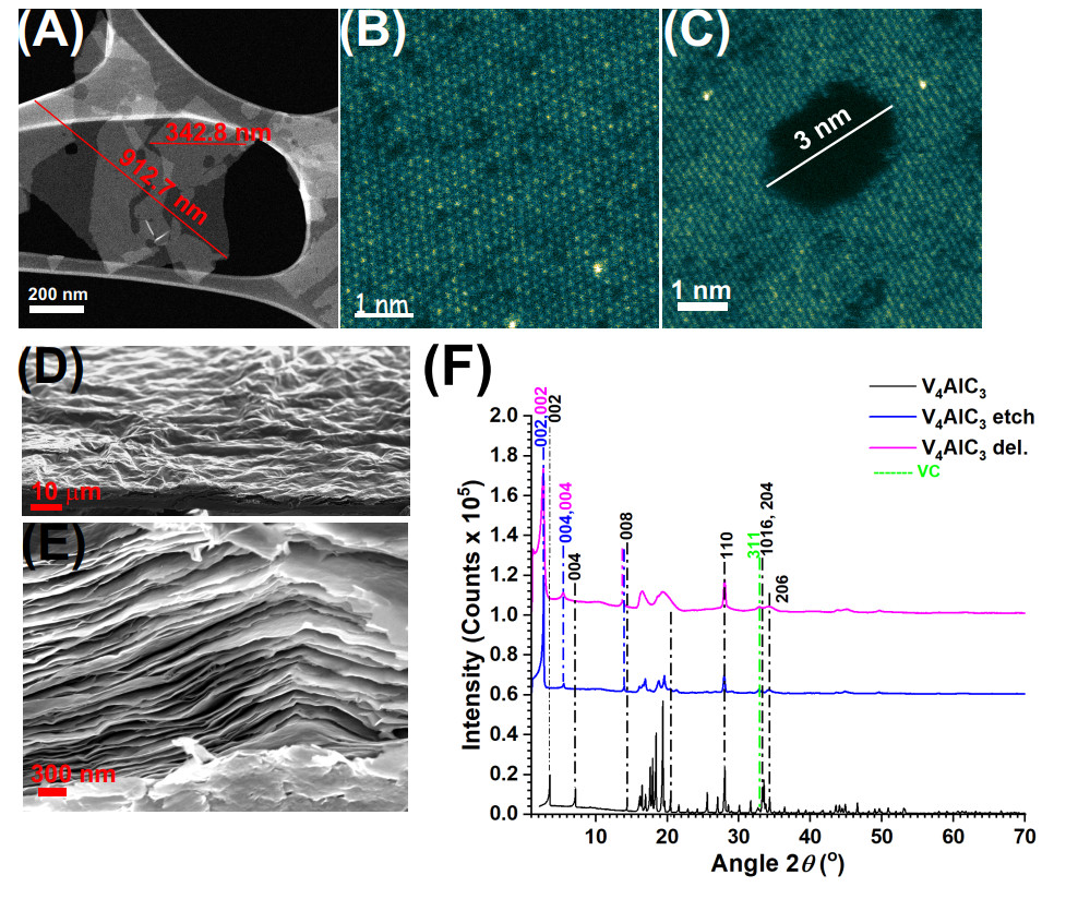
The MXene V$$ _{4} $$C$$ _3 $$T$$ _z $$ was synthesized according to acid-etching and delamination procedures recently reported by us[13]. The synthesized material consisted of a mix of monolayers and few-layer material with a flake size of $$ \approx $$ 200 nm to 2.0 $$ \mu $$m [Figure 1A]. In our previous work, we confirmed the 4:3 atomic structure and the elemental composition including V, C and surface functional groups T$$ _z $$$$ = $$ O, F and Cl, using a range of spectroscopy methods including high-resolution transmission electron microscopy (HRTEM) and EELS [Figure 1B and C][13]. Equally, the presence of V vacancies and pores, and hence the V$$ _{4-x} $$C$$ _3 $$T$$ _z $$ composition, would be more accurate, were identified, which is a desired property for energy storage applications to promote ion transport across nanosheets [Figure 1C][13]. For denomination simplification, we use V$$ _{4} $$C$$ _3 $$T$$ _z $$ throughout the text. V$$ _{4} $$C$$ _3 $$T$$ _z $$ electrodes were obtained by vacuum filtration and used for electrochemical studies [Figure 1D and E].

Figure 1. (A) HAADF-STEM image of V4C3Tz flakes with lateral size indicated, (B and C) HAADF-STEM images of a V4C3Tz monolayers showing vacancies and a (C) pore, (D and E) SEM images of a V4C3Tz film obtained by vacuum filtration, (F) XRD patterns of V4AlC3 and corresponding etched and delaminated samples. Reprinted from[13], Copyright (2024), with permission from Elsevier.

In our previous work, XRD studies and Rietveld refinement confirmed the crystal structure of V$$ _4 $$AlC$$ _3 $$ corresponding to the P 6$$ _3 $$/m m c hexagonal space group with lattice parameters: a $$ = $$ b $$ = $$ 2.92795(6) $$ \mathscr{B} $$, c $$ = $$ 22.7116(5) $$ \mathscr{B} $$, $$ \alpha $$$$ = $$$$ \beta $$$$ = $$ 90$$ ^{\circ} $$, $$ \gamma $$$$ = $$ 120$$ ^{\circ} $$[13]. A table with the full structural description and a report of minor secondary phases is reproduced in the Supplementary Table S1. The successful etching and delamination were confirmed by XRD, which was demonstrated by a characteristic shift to lower 2$$ \theta $$ angles and broadening of the 002, 004 and 008 reflections [Figure 1F][13,31]. As calculated from the 2$$ \theta $$ angles of the 002 reflection, the c lattice parameters were: 29.6451 $$ \mathscr{B} $$ (d space of 14.8225 $$ \mathscr{B} $$) for the etched sample and 30.3364 $$ \mathscr{B} $$ (d space of 15.1682 $$ \mathscr{B} $$) for the delaminated sample.

Electrolyte formulations

The electrochemical activity of V$$ _4 $$C$$ _3 $$T$$ _z $$ film electrodes was studied as a function of LiBr/H$$ _2 $$O electrolyte concentration. A range of electrolyte concentrations of 5 m, 7.5 m, 10 m, 12.5 m, 15 m, 17.5 m and 19 m were considered. The corresponding LiBr/H$$ _2 $$O weight, volume and mol ratios are tabulated in Table 1. According to the definition of WISEs[15,16], the salt should outnumber the water both in weight and volume, i.e., wt. LiBr/wt. H$$ _2 $$O $$ > $$ 1 and vol. LiBr/vol. H$$ _2 $$O $$ > $$ 1. The former condition is fulfilled by the 12.5 m, 15 m, 17.5 m and 19 m electrolytes but none fulfills the latter. Previously reported WISE systems have a mol H$$ _2 $$O/mol salt ratio of 2.5[27], whereas for hydrate melts such ratio is 2[17,27]. Here, the 19 m LiBr electrolyte has a mol H$$ _2 $$O/mol LiBr $$ = $$ 2.9, which is higher than 2.5 for a WISE. Preliminary molecular dynamic simulations of the electrolyte at 5 m, 10 m, 17.5 m and 19 m concentrations were performed [Supplementary Section S2]. Radial distribution functions of water-water molecules showed a slight decrease of the main peak at 2.8 $$ \mathscr{B} $$ while a new "peak" at 3.4 $$ \mathscr{B} $$ barely emerged as the molality increased [Supplementary Figure S1A]. For a reference 30 m KAcO/1 m ZnAcO WISE, a main peak at 2.8 $$ \mathscr{B} $$ was completely replaced by a well-defined peak at 3.4 $$ \mathscr{B} $$, and these correlated changes are attributed to the replacement of a water hydration shell by indirect "bridging" interactions where two water molecules interact indirectly via an ion[23]. However, this was not the case for the 19 m LiBr/H$$ _2 $$O electrolyte. In addition, the water-water coordination numbers (CN) decreased from 4.7 (5 m) to 3.7 (19 m) [Supplementary Figure S1B], whereas in the reference 30 m KAc/1 m ZnAc WISE, the CN is 0.63. The H$$ _2 $$O-Li and H$$ _2 $$O-Br CN remained small (0.78 and 1.1, respectively, for the 19 m electrolyte) whereas the Li-Br CN remained high (1.8 for the 19 m electrolyte) [Supplementary Figure S1B]. These results indicated predominant H$$ _2 $$O-H$$ _2 $$O and Li-Br interactions in the 19 m electrolyte, thus not fulfilling the conditions of a WISE.

Table 1

LiBr/H$$ _2 $$O electrolyte properties. Molality and weight, volume and mol LiBr/H$$ _2 $$O ratios. The latter also indicated as mol H$$ _2 $$O/LiBr ratio

LiBr/H$$ _2 $$O electrolytes
Molality57.51012.51517.519
wt. LiBr/wt. H$$ _2 $$O0.430.650.871.091.301.521.65
vol. LiBr/vol. H$$ _2 $$O0.130.200.270.340.410.480.54
mol LiBr/mol H$$ _2 $$O0.090.140.180.230.270.320.34
mol H$$ _2 $$O/mol LiBr11.117.405.554.443.703.172.92

Based on these arguments, we consider the 12.5 m, 15 m, 17.5 m and 19 m electrolytes as high-concentration electrolytes, where the 19 m is a HCE but not WISE, whereas the other 5 m, 7.5 m, 10 m electrolytes are considered low-concentration or salt-in-water electrolytes.

Electrochemical windows

The stability of EWs was studied. CVs were performed at 0.5 mV s-1 from OCP to negative potentials vs. Ag (all the potentials in this work are referred to as an Ag pseudoreference electrode) in steps of 0.05 V. The same was done for positive potentials using a different electrode. In addition, CAs were performed from OCP to the same potentials for 15-30 min ensuring current stabilization and using different electrodes for positive and negative potentials vs. OCP. The OCP of the electrodes varied with electrolyte concentration.

For the test using the 10 m electrolyte and negative EW, the OCP was at 0.37 V [Supplementary Figure S3A]. In this electrolyte, significant CV cathodic currents were observed at potentials $$ < $$ -0.7 V [Supplementary Figure S3A]. A stable chronoamperometric (CA) current at -0.7 V was -30 $$ \mu $$A cm-2 [Supplementary Figure S3C]. For the positive EW, the OCP was at 0.4 V; significant anodic CV currents were observed at potentials $$ > $$ + 0.7 V [Supplementary S3B], and a stable CA current at 0.7 V was 20 $$ \mu $$A cm-2 [Supplementary S3D]. The current at potentials $$ < $$ -0.7 V is attributed to HER. At positive potentials, the anodic current at potentials $$ > $$ 0.7 V could be well related to OER and/or to electrolyte oxidation processes involving the Br$$ ^{-} $$ anion[24].

The EWs for the other low-concentration electrolytes, 5 m and 7.5 m followed a similar behavior at the negative limit, having and onset of HER at -0.7 V [Supplementary Figure S2]. However, at the positive limit of the EW, the onset of high anodic currents was at a lower potential of 0.6 V for the electrode tested in the 5 m electrolyte [Supplementary Figure S2B]. For the electrode tested in the 7.5 m electrolyte, the electrochemically stable positive EW limit was 0.7 V [Supplementary Figure S2D].

For the 15 m electrolyte and positive EW, the OCP was 0.54 V; significant cathodic CV currents were observed at potentials $$ < $$ -0.7 V [Supplementary Figure S5A], and a stable CA current at -0.7 V was -50 $$ \mu $$A cm-2 [Supplementary Figure S5C]. For the positive EW, the OCP was 0.54 V; significant anodic CV currents were observed at potentials $$ > $$ 0.8 V [Supplementary Figure S5B], and a stable CA current at 0.8 V was 15 $$ \mu $$A cm-2 [Supplementary Figure S5D]. The stability limits of the EW for the 12.5 m electrolyte were -0.7 V and 0.8 V [Supplementary Figure S4].

For the 19 m electrolyte and negative EW, the OCP was 0.5 V; significant CV cathodic currents were observed at potentials $$ < $$ -0.7 V [Supplementary Figure S7A]. CAs showed a stabilized current of -50 $$ \mu $$A cm-2 at -0.7 V [Supplementary Figure S7C]. For the positive EW, significant anodic CV currents were observed at potentials $$ > $$ 0.8 V [Supplementary Figure S7B], and a stable CA current at 0.8 V was 5 $$ \mu $$A cm-2 [Supplementary Figure S7D]. The stability limits of EWs for the 17.5 m electrolyte were -0.7 V and 0.8 V [Supplementary Figure S6].

A suitable observation on all these tests is that the evolving currents beyond the set negative EW limits are larger than those evolving beyond the set EW positive limits, describing a larger electrochemical activity due to HER than the activity at the positive limits.

Based on these studies, EW potential limits were set for further studies. A negative EW potential limit of -0.7 V was set for tests in all electrolytes. Positive EW potential limits were set as 0.8 V for tests in 12.5 m, 15 m, 17.5 m and 19 m electrolytes; and 0.7 V for tests in 5 m, 7.5 m and 10 m electrolytes. An EW positive potential limit of 0.6 V applies to tests in the 5 m electrolyte. However, a setting at 0.7 V was preferred for the sake of comparison of charge storage in a common EW with tests in 7.5 m and 10 m electrolytes. Cycling stability studies indeed showed that a positive EW limit of 0.7 V leads to poor cycling stability and poor CE in these electrolytes (Sections "Cyclability tests", "Analysis of CVs of cycling tests"), thus, confirming that a lower positive EW limit of a maximum of 0.6 V should be used.

Cyclic voltammetry tests

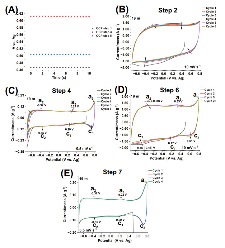
Next, the electrochemical activity of V$$ _4 $$C$$ _3 $$T$$ _z $$ film electrodes was studied by CV in the range of 5-19 m electrolytes at the defined EWs. A first observation is that the testing history of the electrode was important for the electrochemical activity observed. In order to illustrate the case, the electrochemical response to a "standard testing sequence" is described in detail for an experiment using the 19 m LiBr electrolyte [Figure 2]. Typically, in step 1, an OCP was read [Figure 2A], which was 0.46 V. Then, in step 2 a CV was run at 10 mV s-1 for five cycles [Figure 2B]. Here the current decreased over cycling, perhaps implying electrochemical activity of surface groups/surface oxides that faded over time. In step 3, an OCP was read as 0.61 V [Figure 2A]. Thus, the electrochemical activity of the previous CV affected the OCP, typically, shifting it to higher potentials. In step 4, a CV was run at 0.5 mV s-1 for 5 cycles [Figure 2C]. In this CV, it is evident that the lower potential limit of -0.7 V for the EW implied HER, which, however, decreased over cycling. At the same time, some cathodic waves emerged at c$$ _1 $$$$ = $$ 0.20 V and c$$ _2 $$$$ = $$ -0.35 V and some anodic waves emerged at a$$ _1 $$$$ = $$ 0.27 V and a$$ _2 $$$$ = $$ -0.37, which increased over cycling. We hypothesize that this might be due to formation of a passivation layer that leads to the decrease of the HER while originating the (c$$ _1 $$, c$$ _2 $$, a$$ _1 $$, a$$ _2 $$) electrochemical activity (EIS studies - in "SPEIS studies" section -, showed evidence of an interfacial film at the electrode-electrolyte interface for tests in 17.5 m and 19 m electrolytes). In addition, there were cathodic and anodic peak currents at c$$ _3 $$$$ = $$ 0.73 V and a$$ _3 $$$$ = $$ 0.8 V, respectively, that developed over cycling. As previously stated, this electrochemical activity might be related to OER or to oxidation processes involving the Br$$ ^{-} $$ anion. In step 5, an OCP was read as 0.5 V [Figure 2A]. In step 6, a CV was run at 10 mV s-1 for 25 cycles with the aim of activating the electrode, i.e., promoting electrolyte infiltration within the interlayer spaces of the film electrode [Figure 2D]. It is clear that in this CV, the (c$$ _1 $$, c$$ _2 $$, a$$ _1 $$, a$$ _2 $$) electrochemical activity decreased over cycling - the potentials are slightly different than in step 4 [Figure 2C] due to the different scan rates. This may indicate that this activity is related to a passivation layer, that upon cycling was disturbed. In step 7, a CV was run at 0.5 mV s-1 for three cycles. It is clear that the HER activity decreased at -0.7 V. The (c$$ _1 $$, c$$ _2 $$, a$$ _1 $$, a$$ _2 $$) electrochemical activity was present. The current peaks at c$$ _3 $$ and a$$ _3 $$ were definitely developed over the activation processes and were larger than in step 4. Further cycling tests describe how the c$$ _3 $$ and a$$ _3 $$ activity leads to poor cycling stability (Section "Cyclability tests").

Figure 2. CV tests of V$$ _4 $$C$$ _3 $$T$$ _z $$ film electrodes in 19 m LiBr electrolyte, a half-cell setup and a -0.7 to 0.8 V vs. Ag electrochemical window. (A) OCPs at steps 1, 3 and 5, (B) CV at 10 mV s-1 (step 2), (C) CV at 0.5 mV s-1 (step 4), (D) CV at 10 mV s-1 (step 6), (E) CV at 0.5 mV s-1 (step 6). The arrows indicate currents at specified potentials or within a potential range from cycle 1 to cycle n.

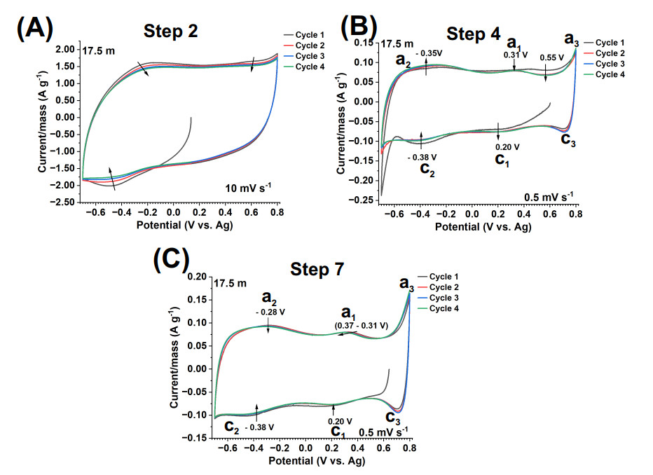
The electrochemical processes undergone by the V$$ _4 $$C$$ _3 $$T$$ _z $$ electrode tested in 17.5 m LiBr electrolyte were similar to those in 19 m LiBr, yet with key differences. Following the standard testing sequence, in step 2, CVs were run at 10 mV s-1, showing a decreasing current over cycling [Figure 3A]. In step 4, CVs at 0.5 mV s-1 showed HER at -0.7 V, which decreased over cycling [Figure 3B]. Electrochemical activity emerged at c$$ _1 $$$$ = $$ 0.20 V and c$$ _2 $$$$ = $$ -0.38 V. Unlike in the test in the 19 m LiBr, where the current at c$$ _2 $$ remained stable, in the 17.5 m electrolyte this current decreased over cycling. This current peak was most likely influenced by the HER activity at -0.7 V. Anodic currents were observed at a$$ _1 $$$$ = $$ 0.31 V and a$$ _2 $$$$ = $$ - 0.35 V. Over cycling, the former was stable whereas the latter increased. In addition, an anodic current at 0.55 V decreased, while the c$$ _3 $$$$ = $$ 0.73 V and a$$ _3 $$$$ = $$ 0.8 V current peaks increased. This current increase was less pronounced than in the case of the 19 m LiBr test. This may indicate that the 17.5 m LiBr is more effective in shifting the related OER/Br$$ ^{-} $$ oxidation to higher potentials. Thus, both, a passivation effect suppressing HER and a shift of the OER/Br-1 oxidation to higher potentials appeared to occur when using the 17.5 m LiBr electrolyte. Next, a CV at 0.5 mV s-1 was performed directly (step 7), without the activation procedure (step 6) [Figure 3C]. Here, in comparison with the CVs in step 4, the (c$$ _1 $$, c$$ _2 $$, a$$ _1 $$, a$$ _2 $$) currents became more enhanced and stable. Thus, this supports the hypothesis that this activity is related to a passivation layer formed in step 4, which was not removed by an electrode activation procedure this time. The c$$ _3 $$ and a$$ _3 $$ current peaks remained at low current values. No HER activity was observed. Thus, we can conclude that in the 17.5 m LiBr electrolyte, a stable electrochemical activity was achieved, where the contribution of the (c$$ _1 $$, c$$ _2 $$, a$$ _1 $$, a$$ _2 $$) current peaks was significant and stable upon cycling.

Figure 3. CV tests of V$$ _4 $$C$$ _3 $$T$$ _z $$ film electrodes in a 17.5 m LiBr electrolyte, a half-cell setup and a -0.7 to 0.8 V vs. Ag electrochemical window. (A) CV at 10 mV s-1 (step 2), (B) CV at 0.5 mV s-1 (step 4) and (C) CV at 0.5 mV s-1 (step 7). The arrows indicate currents at specified potentials or potential ranges from cycle 1 to cycle n. No activation was performed in this electrode (10 mV s-1 for 25 cycles, step 6).

The electrochemical processes of the V$$ _4 $$C$$ _3 $$T$$ _z $$ electrode tested in 15 m electrolyte [Supplementary Figure S8] were similar to those undergone when using the 19 m electrolyte [Figure 2]. Upon activation by a CV at 10 mV s-1 (step 6), the electrochemical processes related to (c$$ _1 $$, c$$ _2 $$, a$$ _1 $$, a$$ _2 $$) decreased [Supplementary Figure S8C], just as in the case of the 19 m test [Figure 2D]. The CV at 0.5 mV s-1 in step 7 [Supplementary Figure S8D] was similar to the corresponding CV test in 19 m LiBr [Figure 2E]. Both had large c$$ _3 $$ and a$$ _3 $$ current peaks that were enhanced during step 7, leading to cycling instability (Section "Cyclability tests").

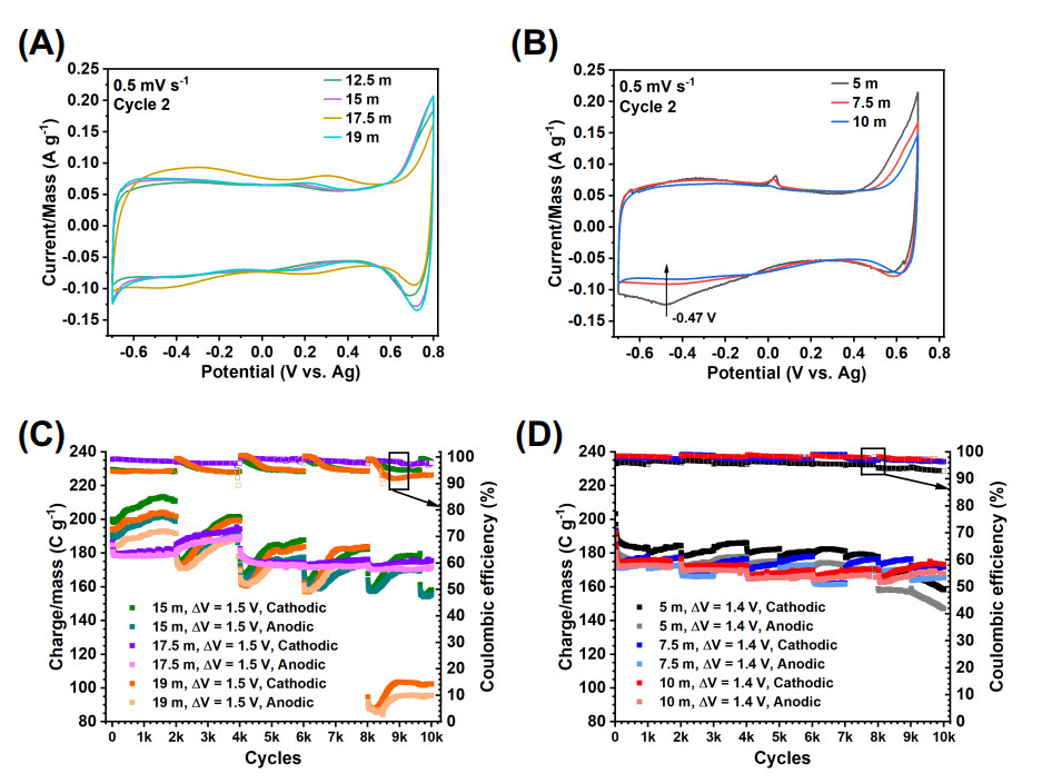
Similar electrochemical processes were undergone by the V$$ _4 $$C$$ _3 $$T$$ _z $$ electrode tested in the 12.5 m electrolyte. Particularly, the (c$$ _1 $$, c$$ _2 $$, a$$ _1 $$, a$$ _2 $$) electrochemical processes were shared for electrodes tested in 12.5 m to 19 m LiBr electrolytes [Figure 4A].

Figure 4. Charge storage performance of V$$ _4 $$C$$ _3 $$T$$ _z $$ film electrodes in a half-cell setup. (A) CVs (step 7 and cycle 2) at 0.5 mV s-1 in a -0.7 to 0.8 V vs. Ag electrochemical window and in a 12.5 m, 15 m, 17.5 n and 19 m LiBr electrolytes, (B) CVs (step 7 and cycle 2) at 0.5 mV s-1 in a -0.7 to 0.7 V vs. Ag electrochemical window and in a 5 m, 7.5 m and 10 m electrolytes, (C and D) charge storage (cathodic and anodic) per unit mass vs. cycle number curves for electrodes tested using CV at 10 mV s-1 and in (C) 15 m, 17.5 m and 19 m and (D) 5, 7.5 and 10 m LiBr electrolytes.

The CV tests in electrodes tested in $$ \leq $$ 10 m LiBr electrolytes and a -0.7 to 0.7 EW showed a different electrochemical signature than the electrodes tested in 19-12.5 m LiBr [Figure 4B]. The (c$$ _1 $$, c$$ _2 $$, a$$ _1 $$, a$$ _2 $$) electrochemical processes were not present. The new electrochemical signature is illustrated for the case of the test in the 7.5 m electrolyte [Supplementary Figure S9]. Following the standard testing sequence, in step 2, a CV test at 10 mV s-1 showed a decrease in electrochemical activity [Supplementary Figure S9A]. This indicated that this phenomenon is linked to electrode properties rather than to the electrolyte concentration. In step 4, a CV was performed at 0.5 mV s-1 [Supplementary Figure S9B]. Unlike the CV tests in $$ \geq $$ 10 m LiBr, no drastic cathodic currents at -0.7 V were present [Supplementary Figure S9D]. Instead, mild cathodic currents were present at -0.43 to -0.54 V [Figure 4B, [Supplementary Figure S9B]. This indicated a less vigorous HER, contrary to what would be expected in a low-concentration electrolyte. This current decreased as the electrolyte concentration increased from 5 m to 10 m [Figure 4B]. This may indicate better passivation as the electrolyte concentration increased.

An anodic peak at 0.0 V was proved to be related to the glassy carbon current collector [Supporting Information, Supplementary Section S5, Supplementary Figure S10]. The cathodic/anodic currents at c$$ _3 $$$$ = $$ 0.6 V and a$$ _3 $$$$ = $$ 0.7 V were of similar magnitude to those in the case of the tests in $$ \geq $$ 10 m electrolyte [Supplementary Figure S9D]. However, the a$$ _3 $$ anodic current was clearly enhanced as the electrolyte concentration decreased from 10 m to 5 m [Figure 4B]. This is expected for the electrode tested in the 5 m electrolyte, which, for the sake of charge storage comparison across electrodes tested in the 7.5 m and 10 m electrolytes, was tested beyond the determined positive EW potential limit of stability (0.6 V). In step 7, a CV was performed at 0.5 mV s-1 without an activation process [Supplementary Figure S9C]. The electrochemical activity was the same as in step 4, but with stabilized HER currents. Except for the indicated differences, similar electrochemical processes were observed in the CVs performed in all the other $$ \leq $$ 10 m LiBr electrolytes [Figure 4B].

In order to evaluate the nature of the charge storage contribution of the V$$ _4 $$C$$ _3 $$T$$ _z $$ electrodes, CVs of electrodes tested in 5 m and 17.5 m LiBr and at a 0.5 to 500 mV s-1 scan rate range were analyzed using TB Robot, a supervised machine learning tool that reports on the "capacitive tendency" of a CV[32,33]."Capacitive tendency" is the probability ($$ \% $$) of the shape of a CV to correspond to the shape of a signal of an ideal capacitor (box-like shape, 100$$ \% $$ capacitive tendency) or battery shape (0$$ \% $$ capacitive tendency)[33]. Results showed a 52$$ \% $$-52.5$$ \% $$ capacitive tendency at 0.5 and 1 mV s-1 for electrodes tested in both electrolytes, and 96$$ \% $$-96.2$$ \% $$ for higher scan rates [Supplementary Figure S11]. In the former case, the non-capacitive 47.5$$ \% $$-48$$ \% $$ was attributed to the large "faradaic type" currents at c$$ _3 $$ and a$$ _3 $$, enhanced at the 0.5 and 1 mV s-1 scan rates and decreased in the 17.5 m electrolyte. Therefore, the V$$ _4 $$C$$ _3 $$T$$ _z $$ electrodes have a predominant capacitive charge storage mechanism in the LiBr electrolyte.

In summary, the electrodes tested in 19 m, 17.5 m, 15 m, and 12.5 m showed a similar electrochemical activity consisting of (c$$ _1 $$, c$$ _2 $$, a$$ _1 $$, a$$ _2 $$) and c$$ _3 $$ and a$$ _3 $$ current peaks. The former correlated to an interfacial film, confirmed by EIS studies (Section "SPEIS studies"), and the latter correlated to likely OER/Br$$ ^{-} $$ oxidation processes (also supported by EIS studies, Section "SPEIS studies"). The electrodes tested in 10 m, 7.5 m and 5 m electrolytes showed a different electrochemical activity with absence of (c$$ _1 $$, c$$ _2 $$, a$$ _1 $$, a$$ _2 $$) current waves (and no evidence of interfacial film, EIS studies, Section "SPEIS studies") but an increasing c$$ _3 $$ and a$$ _3 $$ current activity as the electrolyte concentration decreased to 5 m. The charge storage mechanism of V$$ _4 $$C$$ _3 $$T$$ _z $$ was confirmed as capacitive, except for the current peaks at c$$ _3 $$ and a$$ _3 $$.

Cyclability tests

Cyclability tests revealed further insights into charge storage mechanisms and EW stability. Electrodes were tested by CV at 10 mV s-1 up to 10, 000 cycles in 7.5 m, 10 m, 15 m, 17.5 m and 19 m LiBr [Figure 4C and D]. In order to understand the cycling trends, the following note is relevant. Preliminary tests showed that the Celgard separator is not stable in LiBr and tends to degrade over cycling. For this reason, the separator and electrolyte were changed every 1, 000 or 2, 000 cycles. Other separators, including glass fiber, were tested with no better performance.

The cycling performance of the electrodes tested in the low-concentration electrolytes 5 m and 7.5 m was relatively stable but highly irreversible [Figure 4D]. Namely, cathodic capacity retention of 77.8$$ \% $$ (5 m) and 83.5$$ \% $$ (7.5 m) and CE of 96.8 to 92.9$$ \% $$ (5 m) and 99.9 to 96.3$$ \% $$ (7.5 m) over the 10, 000 cycle tests. The electrode tested in the 10 m electrolyte had comparatively better cycling stability (cathodic capacity retention of 86.2$$ \% $$ over 10, 000 cycles) and better reversibility (CE of 99.0 to 96.4$$ \% $$ over the 10, 000 cycles test) [Figure 4D]. The capacity decreased with the electrolyte concentration, e.g., for the cathodic capacity: 5 m (182.5 C g-1, cycle 5, 000) $$ > $$ 7.5 m (173.4 C g-1, cycle 5, 000) $$ > $$ 10 m (168.1 C g-1, cycle 5, 000).

The cycling performance of the electrodes tested in the high-concentration electrolytes 15 m, 17.5 m and 19 m electrolytes was different as compared to those tested in the low-concentration electrolytes [Figure 4C]. For the tests in the 15 m and 19 m electrolytes, there was an increasing capacity trend for each set of 2, 000 cycles with a poor CE. For instance, in the 15 m LiBr, the CE was 94.4-95.4$$ \% $$ at cycles 10-1970, which is poorer than the CE for the 10 m electrolyte. However, the capacity of electrodes tested in these electrolytes was larger than the capacity of electrodes tested in the low-concentration electrolytes and followed a decreasing trend. For example, for the electrode tested in the 15 m electrolyte, the cathodic capacity was 213.5 C g-1 (maximum), 184.5 C g-1 (at cycle 5, 000) and 155.2 C g-1 (minimum) with a cathodic capacity retention of 72.6$$ \% $$ over the 10, 000 cycles test. Such capacity was higher than the capacity of the electrode tested in the 10 m electrolyte. The electrode tested in the 19 m electrolyte had a similar capacity and CE as the electrode tested in the 15 m electrolyte, but a poorer cycling stability, especially at the last 2, 000 cycles.

On the other hand, the electrode tested in the 17.5 m electrolyte, although with a slightly lower capacity than the electrode tested in the 15 m electrolyte (195.5 C g-1 (maximum), 174.5 C g-1 (at cycle 5, 000) cathodic capacity), had a superior CE (CE of 99.9 to 96.5$$ \% $$ over 10, 000 cycles) and capacity retention (cathodic capacity retention of 88.0$$ \% $$ over 10, 000 cycles). This offers the best performance balance amongst all the electrolytes. The cyclability over the first 4, 000 cycles can be further improved with further electrode engineering.

In general, the electrodes tested in the high-concentration electrolytes have a higher capacity but poorer cycling stability and CE than the low-concentration electrolytes. This is correlated to electrolyte properties (Section "Electrolyte properties"). However, electrodes tested in the 7.5 m and 5 m low-concentration electrolytes have a different source of instability linked to an irreversible electrochemical activity at the positive EW potential limit, as demonstrated in the next section ("Analysis of CVs of cycling tests"), which indicates that the EW positive limit should be lowered to at least 0.6 V. This instability is improved for the test in the 10 m electrolyte. The 17.5 m electrolyte offers the best performance balance among all the electrolytes.

Analysis of CVs of cycling tests

A close examination of the electrochemical activity revealed by CVs of the cyclability tests gave insights into the cycling trends. The test sequence followed here was: (Step 1) 10 mV s-1 for five cycles, (Step 2) a CV at 0.5 mV s-1 for five cycles and (Step 3) a CV at 10 mV s-1 for 25 cycles. Due to an analysis of CVs at 10 mV s-1, instead of 0.5 mV s-1 analyzed in the previous section "Cyclic voltammetry tests", a different notation is used to describe the CV electrochemical activity.

The CVs of the tests in the 10 m electrolyte showed fairly stable activity over cycling [Supplementary Figure S12]. The electrochemical activity at 0.045 V (A, anodic), 0.7 V (B, anodic), 0.53 V (C, cathodic), -0.52 V (D, cathodic) and -0.53 V (E, anodic) potentials was analyzed. The anodic current peak A has already been identified as correlated to a reaction with the glassy carbon current collector. The current peaks B and C (c$$ _3 $$ and a$$ _3 $$ in CVs at 0.5 mV s-1 in the previous section "Cyclic voltammetry tests") increased over cycling and decreased when the separator and electrolyte were changed, e.g., cycle 1, 010 vs. all the previous ones [Supplementary Figure S12A-C]. This indicated that this electrochemical activity is linked to electrolyte reaction. On the other hand, the activity in D (identified at -0.43 to -0.53 V in the CVs at 0.5 mV s-1, Figures 4B, Supplementary Figure S9B) is linked to HER that however was stabilized over cycling.

The CVs of the tests in the 15 m LiBr electrolyte showed a different electrochemical activity [Supplementary Figure S13]. The same current peaks as in the case of the 10 m electrolyte were found at 0.045 V (A, anodic), 0.8 V (B, anodic), 0.60 V (C, cathodic), -0.52 V (D, cathodic) and -0.53 V (E, anodic). In addition, an anodic current at 0.28 V (A') emerged at cycle 2 and moved to 0.16 V on the following cycles [Supplementary Figure S13A]. Other new cathodic currents emerged at 0.08 V, which moved to -0.02 V over cycling (C'), and at -0.40 V (C"). The latter most likely is current D but displaced over cycling. A current at -0.33 V (F) grew over cycling. At cycle 2, 000, the current A was enhanced, along with the currents B and C [Supplementary Figure S13A]. At the same time, C' and C" vanished while a current at -0.20 V (C"') emerged. Upon change of separator and electrolyte, at cycle 2002, the activity in B, C and C"' decreased drastically. From cycles 2, 002 to $$ \approx $$ 2, 170, the charge storage decreased and the activity of B, C, and C"' remained small [Supplementary Figure S13B]. This is linked to a period of hampered electrolyte access and, thus, indicated that activity at B, C and C"' is related to electrolyte reactions at inner sites of active materials. Since the activity at C' and C"' was not present in the 10 m LiBr test, which was performed up to 0.7 V, instead of 0.8 V in the 15 m LiBr test, such electrochemical activity might be linked to activity in B and C current peaks. Upon subsequent cycling, the charge storage increased up to cycle 4, 000, where, as in cycle 2, 000, the activity in A, B, C and C"' was enhanced [Supplementary Figure S13B]. After a new electrolyte and separator change, the trend repeated [Supplementary Figure S13C].

The CVs of the tests in the 19 m LiBr electrolyte showed similar electrochemical activity and evolution over cycling than the 15 m [Supplementary Figure S14].

In summary, the electrochemical activity in A is related to the current collector-electrolyte interface. The electrochemical activity in B and C is definitely linked to electrolyte reaction and explains the poor cycling stability and poor CE of the electrodes tested in 5 m and 7.5 m electrolytes.

Electrode rate performance

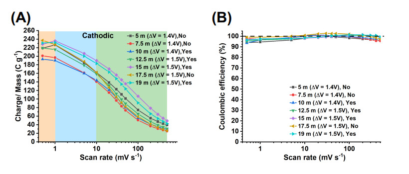
The charge storage evolution over CV scan rate and as a function of the LiBr electrolyte concentration was studied. Electrodes were tested by CV (at 0.5 to 500 mV s-1 scan rates) in 5 m to 19 m LiBr electrolytes [Supplementary Figure S15]. The cathodic and anodic charge per each scan rate and the CE [Figure 5 and Supplementary Figure S16] were calculated. The trends of the cathodic and anodic charge vs. scan rates were similar [Supplementary Figure S16A-C]. At scan rates $$ \leq $$ 5 mV s-1, the CE ranged from 93.7$$ \% $$ (10 m, at 0.5 mV s-1) to 100$$ \% $$ (17.5 m, 5 mV s-1) describing a better reversibility for the electrode tested in the 17.5 m electrolyte [Figure 5B, Supplementary Figure S16D]. From 10 to 50 mV s-1, the CE improved reaching 100$$ \% $$ for electrodes tested on most electrolytes. At scan rates $$ \geq $$ 100 mV s-1, the trend showed a decrease in CE, but it remained around 100$$ \% $$ with larger deviations for the low-concentration 5 m and 7.5 m electrolytes.

Figure 5. (A) Cathodic charge storage vs. scan rate curves for electrodes tested in 5 to 19 m LiBr electrolytes, and (B) the corresponding Coulombic efficiency curves. The notes "Yes" or "No" indicate whether the electrode underwent an activation procedure (step 6).

Given the similar trends of cathodic and anodic charge vs. scan rate [Supplementary Figure S16], an analysis of the trends across electrolytes is based on the cathodic charge [Figure 5A]. The charge storage vs. concentration trends varied according to three different scan rate regimes: very low (0.5 mV s-1), medium (1-10 mV s-1) and high (20-500 mV s-1). The charge vs. electrolyte concentration trends are as follows. At the very low scan rate of 0.5 mV s-1, the charge storage decreased as: 17.5 m $$ > $$ 19 m $$ \approx $$ 15 m $$ > $$ 5 m $$ \approx $$ 12.5 m $$ > $$ 7.5 m $$ > $$ 10 m. At 1-10 mV s-1, the charge storage decreased as: 15 m $$ > $$ 19 m $$ > $$ 17.5 m $$ \approx $$ 5 m $$ > $$ 12.5 m $$ > $$ 7.5 m $$ > $$ 10 m. At 20-500 mV s-1, the charge storage decreased as: 15 m $$ > $$ 19 m $$ > $$ 5 m $$ > $$ 12.5 m $$ > $$ 17.5 m $$ \approx $$ 10 m $$ > $$ 7.5 m.

These charge storage vs. scan rate trends are determined by several variables. First, electrolyte properties, which are a function of concentration, play a key role (Section "Electrolyte properties"). Second, different EWs were considered, i.e., 1.4 V for tests in 5 m, 7.5 m and 10 m electrolytes and 1.5 V for 12.5 m, 15 m, 17.5 m, 19 m electrolytes. A higher charge storage is expected for larger EWs. However, this is not true for the test in 5 m electrolyte (1.4 V EW), which showed higher charge storage than for tests in, e.g., 12.5 m (1.5 V EW) at 1-500 mV s-1 scan rates. A third variable was the performance or not of the activation process (25 cycles at 10 mV s-1, step 6), which was done for tests in 19 m, 15 m, 12.5 m and 10 m electrolytes but not for tests in 17.5 m, 7.5 m and 5 m electrolytes. Electrodes for which activation was not performed had a more drastic decreasing charge storage at high scan rates (20-500 mV s-1). This is the case for the electrode tested in the 17.5 m electrolyte, which had a marked charge storage decrease from 20 to 500 mV s-1, falling below the charge storage of electrodes tested in 5 m (non-activated) and 12.5 m (activated). The same can be said about the non-activated electrode tested in 7.5 m electrolyte, which had a marked charge storage decrease from 20 to 500 mV s-1, which fell below the charge storage of the electrode tested in the 10 m electrolyte (activated). In contrast, electrodes tested in 15 m and 19 m, which underwent activation, did not show a drastic decrease of capacity at 20 to 500 mV s-1 scan rates. Thus, activation procedures are important in keeping a high storage capacity at high scan rates and this becomes important for HCEs.

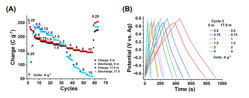
A clear picture of the advantages of the 17.5 m electrolyte over the 5 m electrolyte was provided by GCPL studies performed on electrodes without activation and at a range of rates from 0.25 to 10 A g-1 [Figure 6A]. At the very low current rate of 0.25 A g-1, the electrodes performed poorly in both electrolytes, especially in the 17.5 m, attributed to the high viscosity and low ionic conductivity at this high concentration. However, at 0.5 to 2 A g-1, the electrode tested in the 17.5 m electrolyte had a higher capacity than the electrode tested in the 5 m electrolyte. The CE was below 100$$ \% $$ for the electrode tested in the 5 m electrolyte describing a larger discharge than charge capacity due to the irreversible process at the positive limit of the EW. In contrast, the electrode tested in the 17.5 m electrolyte had a CE slightly close to 100$$ \% $$, evidencing the better reversibility of the charge storage processes. At larger current rates of 4 to 10 A g-1, only the electrode tested in the 5 m electrolyte performs satisfactorily. Here, the negative effects of the high concentration of the 17.5 m electrolyte on the kinetics of the electrode were obvious. When the current rate was reversed to 0.25 A g-1, the electrode tested in the 17.5 m electrolyte achieved 237 C g-1 and a CE of 99%-100$$ \% $$, whereas the electrode tested in the 5 m electrolyte had a very irreversible performance and poor CE. The former was attributed to activation processes undergone during the rate test and facilitated in the 17.5 m electrolyte. GCPL curves [Figure 6B] showed the higher storage time achieved in the 17.5 m electrolyte, and the obvious resistance during charge for electrodes tested in the 5 m electrolyte at the positive limit of the EW, which was less pronounced in the electrode tested in the 17.5 m electrolyte. This resistance is linked to the a$$ _3 $$ high currents shown by CV studies at the positive limit of the EW [Figure 4A and B] and attributed to electrolyte oxidation processes.

Figure 6. GCPL rate studies of electrodes tested at 0.25 to 10 A g-1 current rates in 5 m and 17.5 m LiBr electrolytes. (A) Charge vs. cycles curves, (B) GCPL curves.

Charge storage performance in context

The maximum charge storage achieved by the electrode tested in the 17.5 m electrolyte at 0.5 mV s-1 was 237.1 C g-1 (65.8 mAh g-1)/158 F g-1/745.5 C cm-3, which delivers and energy density of 49.4 Wh kg-1/155.3 mWh cm-3. The electrode tested in the 15 m electrolyte had superior performance at higher scan rates from 1-500 mV s-1, i.e., 235.9 C g-1 (65.5 mAh g-1)/157.2 F g-1/759.6 C cm-3 and 49.1 Wh kg-1/158.2 mWh cm-3. This performance is superior to the 120 F g-1 reported for Ti$$ _3 $$C$$ _2 $$T$$ _z $$ in 19.8 m LiCl and 19.2 m LiBr in a -0.8 to 0.8 V vs. Ag EW[24]. Therefore, this is a superior performance of the V$$ _4 $$C$$ _3 $$T$$ _z $$vs. Ti$$ _3 $$C$$ _2 $$T$$ _z $$ offered in a smaller EW of 1.5 V and, importantly, with no additional contribution of the "desolvation-free" charge storage reported in this previous work[24]. Also important to highlight is that our electrodes are vacuum-filtrated films with no further pore engineering that was reported in this previous work[24], which indicates that the performance of V$$ _4 $$C$$ _3 $$T$$ _z $$ can improve even further in these 15 m or 17.5 m electrolytes.

Equally, the performance of the V$$ _4 $$C$$ _3 $$T$$ _z $$ in 17.5 m or 15 m electrolyte is superior to the performance reported for Ti$$ _3 $$C$$ _2 $$T$$ _z $$ in 21 m KAcO of 77 F g-1/361 C cm-3 in a 1.5 V EW[14]; Ti$$ _2 $$C$$ _2 $$T$$ _z $$ in a Li(TFSI)$$ _{0.7} $$(BETI)$$ _{0.3} $$$$ \cdot $$2H$$ _2 $$O hydrate melt electrolyte of 45 mAh g-1 in a 1.1 V EW[26]; and Ti$$ _3 $$C$$ _2 $$T$$ _z $$ in a Li(TFSI)$$ _{0.7} $$(BETI)$$ _{0.3} $$$$ \cdot $$2H$$ _2 $$O of 141 F g-1 in a 1.1 V EW[27].

Electrolyte properties

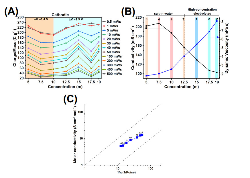
The electrolyte properties were studied. The charge storage vs. concentration trends are summarized in Figure 7A (the same data as in Figure 5A). The ionic conductivity and dynamic viscosity were measured as a function of concentration [Figure 7B]. As the electrolyte concentration increased, the ionic conductivity first increased (from 5 m to 7.5 m concentration) and then decreased (for concentrations $$ > $$ 7.5 m). This is a typical trend of a variety of aqueous and nonaqueous electrolytes of chlorides and acetates of alkali metals and LiTFSI[16,34]. Previous works report on two different ion transport mechanisms before and after a maximum ionic conductivity: "vehicular" and "hopping", respectively[16,34]. The latter involves networks of ion pairs and ion clusters[34]. It must be highlighted that the conductivities of the LiBr aqueous solutions are much higher than the conductivities of a variety of aqueous solutions used as WISEs, including LiCl, KCl, KAcO, and a range of salts based on TFSI, TfO, EMIm, BETI anions and alkali cations[16]. For instance, 207.7 mS cm-1 for 7.5 m LiBr $$ > $$ 160 mS cm-1 for 2 M LiCl $$ > $$ 100 mS cm-1 for all salts based on anions of weaker Lewis basicity than chlorides[16]. The viscosity, on the other hand, increased continuously as the electrolyte concentration increased [Figure 7B]. In addition, a Walden plot confirmed that the LiBr electrolyte at all concentrations is a good ionic conductor[16,35,36] - lying in between theoretical curves corresponding to solutions with 0$$ \% $$ (ideal dilution) and 90$$ \% $$ ion pairing, respectively [Figure 7C]. The ratio of molar conductivity to fluidity decreased as the electrolyte concentration increased, but always lying in the "good ionic conductor" region.

Figure 7. Charge storage performance and electrolyte properties. (A) Charge storage obtained from CVs at a range of scan rates vs. LiBr electrolyte concentration curves, (B) electrolyte conductivity and dynamic viscosity vs. LiBr electrolyte concentration curves, and (C) Walden plot of the LiBr electrolytes at the range of concentration considered in this study (indicated with labels). In (B), the following standard deviations apply to dynamic viscosity values: (5 m) $$ \pm $$ 3.15E-01, (7.5 m) $$ \pm $$ 1.68E-01, (10 m) $$ \pm $$ 1.37E-01, (12.5 m) $$ \pm $$ 4.04E-01, (15 m) $$ \pm $$ 7.94E-02, (17.5 m) $$ \pm $$ 1.05E-01, (19 m) $$ \pm $$ 6.93E-02 mPa s. The corresponding standard deviations for the conductivity values are: (5 m) $$ \pm $$ 1.40, (7.5 m) $$ \pm $$ 1.44, (10 m) $$ \pm $$ 0.92, (12.5 m) $$ \pm $$ 1.55, (15 m) $$ \pm $$ 0.48, (17.5 m) $$ \pm $$ 0.49, (19 m) $$ \pm $$ 0.97 mS cm-1. In (B), the numbers and colors indicate regions of highest (1) to lowest (4) charge storage according to (A). In (C), the upper and bottom dotted lines are theoretical curves corresponding to solutions with 0$$ \% $$ and 90$$ \% $$ ion pairing, respectively[16].

Using the two pieces of evidence, charge storage trends and electrolyte properties, the following conclusions can be drawn. Considering the charge vs. concentration curves at medium to high scan rates (1-500 mV s-1), it is clear that the highest charge storage in the 15 m LiBr electrolyte has place at intermediate conductivity and viscosity values of 129.7 mS cm-1 and 5.42 mPa s [Figure 7B, region 1]. On the other hand, according to the condition wt. LiBr/wt. H$$ _2 $$O $$ > $$ 1 [Table 1], the 12.5 m concentration is a threshold concentration between low-concentration (salt-in-water) and high-concentration electrolytes. Thus, very different ion solvation structures and ion transport mechanisms are expected for concentrations below and above this threshold value[16,34]. In the high-concentration electrolytes regime, the poorer charge storage and poorer performance over scan rates of electrodes tested in 19 m and 17.5 m electrolytes is explained as per the higher viscosity and much lower conductivity of these electrolytes [Figure 7B, region 2]. In the salt-in-water regime, i.e., concentrations $$ < $$ 12.5 m, the highest charge storage performance was obtained for the electrode tested in the 5 m electrolyte [Figure 7B, region 3] and the lowest for the 7.5 m and 10 m electrolytes [Figure 7B, region 4]. This can be explained in terms of the highest conductivity and lowest viscosity of the 5 m electrolyte. Interestingly, despite the expected very different ion structure/ion transport mechanisms, the charge storage achieved in the 12.5 m and 5 m electrolytes was very similar [Figure 7A and B region 3]. This could be partially explained by the poorer performance in the 12.5 m electrolyte of lower ionic conductivity and larger viscosity than the 5 m electrolyte, but larger testing EW.

At the lowest testing scan rate of 0.5 mV s-1, transport processes controlled by diffusion become important. The 17.5 m $$ > $$ 19 m $$ \approx $$ 15 m charge storage trend at this low rate [Figure 7A] indicated that the negative impact on charge storage of a higher viscosity and lower conductivity of the 17.5 m and 19 m electrolytes as compared to the 15 m electrolyte becomes less important. For the rest of the electrolytes, the capacity followed a similar trend to that in the medium-high scan rate regime (12.5 m $$ \approx $$ 5 m $$ > $$ 7.5 m $$ > $$ 10 m), thus applying the same reasoning with respect to the electrolyte properties.

In conclusion, these measured electrolyte properties provided guidance to explain charge storage performance trends as a function of electrolyte concentration. Importantly, these experiments showed that the highest charge storage performance was achieved in the 17.5 m (0.5-1 mV s-1) and 15 m (5-500 mV s-1) electrolytes. Therefore, from the capacity point of view, and considering operation at room temperature, the use of extremely high concentrated electrolytes of 19 m (solubility limit at room temperature) is unnecessary, precluding associated problems of electrolyte crystallization (imminent upon slight variation of temperature or concentration). Further details are provided in the Experimental section. In addition, the results from cyclability tests [Figure 4C], reporting the best performance for the electrode tested in the 17.5 m electrolyte, and despite the high viscosity (but lower than for the 19 m electrolyte), further support that this electrolyte best performs. Performance over scan rates could be further improved with suitable electrode activation processes and further engineering of the electrode and/or utilization at applications at temperatures higher than room temperature.

SPEIS studies

Next, details of ion transport processes were investigated by SPEIS. SPEIS experiments were performed in half-cell setups for electrodes tested in 5 m, 15 m, 17.5 m and 19 m LiBr electrolytes. PEIS was performed every 25 mV during the first cycle of a CV following an OCP to V$$ _1 $$ (cathodic scan 1) to V$$ _2 $$ (anodic scan) to OCP (cathodic scan 2) polarization sequence. Polarization (holding DC potential) was done every 25 mV during 10 min before the performance of each EIS measurement. Measurements were done in a 4 mHz to 250 kHz frequency range. Further details are provided in the Experimental section.

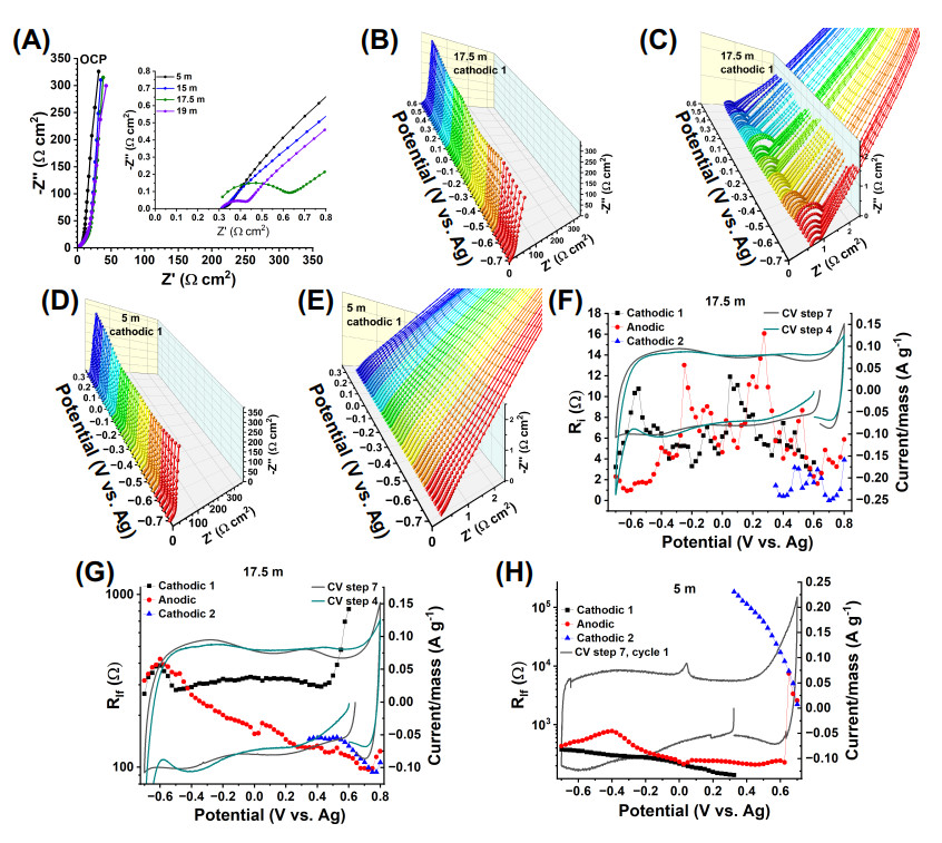
The Nyquist plots of the electrodes tested at OCP and in the 17.5 m and 19 m LiBr electrolytes showed a semicircle at high frequencies, whereas the others tested in 5 m and 15 m LiBr electrolytes did not [Figure 8A]. Such semicircle persisted (and varied) across polarization potentials over the entire EW and all the cathodic and anodic scans (e.g., for tests in the 17.5 m electrolyte shown in Figure 8B, C and Supplementary Figure S17B, D, F). Since the semicircle is present at OCP, its origin cannot be ascribed to a charge transfer resistance but rather an interfacial resistance experienced by the Li$$ ^{+} $$, imposed by the presence of CIP and ACAPs formed at high electrolyte concentrations[27] and which could form a solid electrolyte interface (SEI) of a very different nature than in the case of organic electrolytes[16,18].

Figure 8. (A) Nyquist plots of electrodes polarized at OCP for electrodes tested in 5 m, 15 m, 17.5 m and 19 m LiBr electrolytes, (B), (C) 3D Nyquist plots of electrodes tested in the 17.5 m LiBr electrolyte (cathodic scan 1), (D), (E) 3D Nyquist plots of electrodes tested in the 5 m LiBr electrolyte (cathodic scan 1), (F) R$$ _i $$ and (G) R$$ _{lf} $$vs. polarization potential curves of the PEIS test in 17.5 m electrolyte, as determined by fitting model 1, and CVs at 0.5 mV s-1 (cycle 1) for steps 4 and 7 of the experiment in Figure 3, (H) R$$ _{lf} $$vs. polarization potential curves as determined by fitting model 2 (cathodic scan 1), model 2 (anodic scan from -0.7 to 0.625 V) and model 1 (anodic scan from 0.65 to 0.7 V and cathodic scan 2), and CVs at 0.5 mV s-1 (cycle 1) for step 7 of the standard testing sequence (with no activation, step 6).

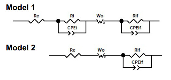
We focus first on the analysis of the EIS data of electrodes tested in the 17.5 m electrolyte. An EIS model 1 was proposed to describe the data [Figure 9].

Figure 9. Equivalent circuits of model 1 and model 2.

The circuit R$$ _e $$[R$$ _i $$CPE$$ _{dl} $$] modeled the data at high frequencies. $$R _e $$ is the sum of the resistance of the electrolyte, separator, and internal resistance of the cell. A parallel circuit [R$$ _i $$CPE$$ _{dl} $$] modeled the properties at the electrode-electrolyte interface, where $$ R_i $$ is the interfacial resistance and $$ CPE_{dl} $$ is the surface double-layer capacitance modeled by a constant phase element, which accounts for a frequency-dispersed capacitance[37,38].

At medium and low frequencies, the 17.5 m EIS data set showed two main contrasting EIS spectra. In the first case, the Nyquist data showed a semi-infinite linear diffusion behavior at medium frequencies (Z' $$ = $$ -Z") followed by a dispersive capacitive behavior at low frequencies, where Z' $$ > $$ -Z" and $$ -\phi $$ is slightly less than 45 $$ ^{\circ} $$ as frequency decreased[39], e.g., at OCP $$ = $$ 0.6 V cathodic scan 1 [Supplementary Figure S19A]. On the other extreme case, the semi-infinite linear diffusion behavior was followed by a semicircle at low frequencies, e.g., at -0.7 V cathodic scan 1 [Supplementary Figure S19A]. As the polarization potential evolved from OCP to either the negative or positive potential limits of the EW, during cathodic and anodic scans, respectively, the low-frequency EIS data evolved from an increasingly dispersed capacitive behavior to the semicircle behavior. The diffusion processes at medium frequencies were adequately modeled by a generalized open circuit terminus Warburg element, W$$ _o $$[40], which is also named "blocked-diffusion Warburg impedance element" with frequency dispersion [Supplementary Equation S1][39]. The "blocked-diffusion Warburg impedance element" term makes reference to "reflective" boundary conditions at the electrode-current collector interface where ions from the electrolyte cannot penetrate the current collector but rather accumulate at the interface giving place to a capacitive response[41,42]. When 0.5p $$ = $$ 0.5 [Supplementary Equation S1], an ideal capacitive behavior occurs (a Z' vs. Z" response where Z' is constant and -Z" increases as the frequency decreases)[39]. A 0.5p $$ < $$ 1, defining the "generalized" version of the open Warburg element, accounts for a frequency dispersion of diffusion processes at low frequency causing a slopping Z' vs. -Z" behavior[39]. The origin of frequency dispersion is attributed to an inhomogeneous charge distribution at the electrode-current collector interface[39]. However, this element was not adequate to model the data at the very low frequencies of none of the EIS spectra - not even the data with the nearest ideal capacitive behavior at low frequencies. This data was only suitably modeled by adding a second [R$$ _{lf} $$CPE$$ _{lf} $$] parallel circuit that describes a boundary condition at a back layer of the electrode in contact with the current collector where ion injection and reactivity take place, typically leading to a semicircle at low frequencies in a Nyquist plot[43]. The \textit{R$$ _{lf} $$} might be correlated to potential side reactions of the surface chemical groups of the MXene with the electrolyte and/or current collector (glassy carbon). Since this Nyquist semicircle was clear as the polarization potential reached the EW limits, a second phenomenon most likely playing a role is HER/OER. Supporting this view, this is typical behavior of the EIS data of fuel cells where OER takes place, and where similar EIS data at low frequency describes oxygen transport limitations[44,45]. The CPE$$ _{lf} $$ was attributed to an R$$ _{lf} $$-associated surface frequency-dispersed capacitance.

The EIS data of the electrode tested in the 17.5 m LiBr electrolyte was adequately modeled using model 1 for the cathodic 1, anodic and cathodic 2 scans [Supplementary Figure S19]. Next, we analyze the evolution of physical parameters with polarization potential.

During the cathodic scan 1, R$$ _{i} $$ evolved from 3.668 $$ \Omega $$ (OCP $$ = $$ 0.6 V) to 3.23 $$ \Omega $$ (-0.7 V) having fluctuations for polarization potentials in between [Figure 8F]. There is no clear correlation of local maxima or minima with the CV activity (0.5 mV $$ s^{-1} $$, cycle 1, steps 4 or 7 of the experiment in Figure 3), except for a maximum of 10.76 $$ \Omega $$ at -0.55 V followed by a decreasing trend down to 3.23 $$ \Omega $$ at -0.7 V, which coincides with the onset HER described by the CV step 4. This indicated that the interfacial film was disturbed by the HER. During the anodic scan, R$$ _{i} $$ followed a similar trend with similar values as the cathodic scan 1 with low values at the negative (-0.6 to -0.4 V) and positive limits (0.55 to 0.8 V) of the EW. This described disruption of the film giving origin to R$$ _{i} $$ by the electrochemical activity at the EW potential limits. During the subsequent cathodic scan 2, R$$ _{i} $$ had similar values to those in the previous anodic scan, describing subsequent stability of this interfacial film. It is clear that R$$ _{i} $$ varied with potential, which may indicate charge transfer for the eventual formation of a stable SEI[16,18].

During the cathodic scan 1, R$$ _{lf} $$ had the highest values of 823.9 $$ \Omega $$ (OCP $$ = $$ 0.6 V) to 339.4 $$ \Omega $$ (0.5 V) for the first five polarization potentials [Figure 8G]. This described the low-frequency charge transfer phenomenon taking place at the back layer of the electrode experiencing a resistance, perhaps due to the stacking of the MXene at this early testing stage (no activation of the electrode was performed before the SPEIS tests). Subsequently, R$$ _{lf} $$ followed a constant trend having values of 308.4 $$ \Omega $$ (0.475 V) to 280.1 $$ \Omega $$ (-0.5 V), stating the average charge transfer resistance of the process in place at the back of the electrode. Afterward, R$$ _{lf} $$ started to increase at -0.525 V to reach a local maximum of 388.5 $$ \Omega $$ at -0.6 V. This enhancement is clearly correlated with the onset of HER observed in a CV at 0.5 mV $$ s^{-1} $$, cycle 1, step 4 of the experiment in Figure 3. Therefore, this R$$ _{lf} $$ parameter has indeed contributions of HER. During the anodic scan, the R$$ _{lf} $$ followed the same trend and similar values as at the end of the cathodic scan 1 from -0.7 to -0.475 V. Afterward, it followed a decreasing trend as the polarization potential increased to positive values to reach a minimum of 97 $$ \Omega $$ at 0.725 V, followed by a slight increase to 123.8 $$ \Omega $$ at 0.8 V. The former decreasing trend described that, whichever this activity at low frequency is, its resistance decreased, and upon reaching the positive limit of the EW, it was enhanced by a different electrochemical process, most likely, OER or Br$$ ^- $$ anion-related reactions. This R$$ _{lf} $$ was, however, much smaller as compared to that obtained in the electrode tested in the 5 m electrolyte (see below). During the subsequent cathodic scan 2, the R$$ _{lf} $$ followed the trend of the previous anodic scan with similar values. This described the reversibility of this activity.

The EIS data of the electrode tested in the 5 m LiBr electrolyte had no semicircle at high frequencies in the cathodic scan 1, and most of the anodic scan from -0.7 to 0.625 V [Figures 8D and E, Supplementary Figure S18A-D]. In this case, a Model 2 was utilized [Figure 9]. The fit data is reported in Supplementary Figure S20. The absence of such a semicircle indicated the absence of an interfacial film. During the cathodic scan 1 from OCP to -0.7 V, R$$ _{lf} $$ evolved from 139.1 to 378.2 $$ \Omega $$ [Figure 8H]. These values were comparable to the average R$$ _{lf} $$ values (280.1 to 300 $$ \Omega $$) during the cathodic scan 1 of the electrode tested in 17.5 m LiBr [Figure 8G]. During the anodic scan from -0.7 to 0.625 V, the R$$ _{lf} $$ evolved from 434.4 $$ \Omega $$ to 228.6 $$ \Omega $$, respectively [Figure 8H]. A maximum at -0.4 V of 779.4 $$ \Omega $$ and a minimum at 0.025 V of 213.5 $$ \Omega $$ were correlated with larger and lower, respectively, Z' at medium-low frequencies, as compared to the rest of the anodic EIS data. The EIS spectra performed at the last three anodic polarization potentials of 0.65 V, 0.675 V and 0.7 V were modeled with model 1 [Figure 9], as a semicircle at the very high frequencies started to evolve [Supplementary Figures S18D and S20D]. At the same time, from 0.35 to 0.7 V, the maximum -Z" progressively decreased evolving into a semicircle at low frequencies clearly pronounced in the last three polarization potentials of the anodic scan [Supplementary Figures S18C and S20C]. This resulted in the very high values of R$$ _{lf} $$ of 7471 $$ \Omega $$, 3363 $$ \Omega $$ and 2587 $$ \Omega $$ at these polarization potentials [Figure 8H]. By observation of the electrochemical activity of the CV at 0.5 mV $$ s^{-1} $$ at these potentials, a current increase is clear [Figure 8H], thus confirming that R$$ _{lf} $$ has contributions of a resistance correlated to a high current process taking place at the positive limit of the EW. This behavior persisted over the subsequent cathodic scan 2 [Supplementary Figures S18E and S20E], where the EIS data was modeled using model 1 [Figure 9] and where R$$ _{lf} $$ remained at very high values [Figure 8H].

It is clear, thus, that a key difference between tests in the 5 m and the 17.5 m electrolytes is the high current and irreversible process at the positive EW potential limit, confirmed by CV (Section "Cyclic voltammetry tests"), analysis of CVs of cycling tests (Section "Analysis of CVs of cycling tests"), GCPL (Section "Electrode rate performance") and EIS studies. The electrode tested in the 17.5 m electrolyte was more stable at the positive EW potential limit allowing the EW to be enlarged up to 0.8 V.

Next, diffusion coefficients were calculated for tests in the 5 m, 15 m, 17.5 m and 19 m LiBr electrolytes at 0 V polarization potential [Supplementary Figure S21D]. This polarization potential was considered an intermediate value within the EW where the secondary processes, other than the intrinsic storage processes of the electrode, observed at the limits of the EW could be avoided. The anomalous diffusion coefficients were calculated according to the parameters derived from the fit using model 2 (5 m and 15 m LiBr EIS data) and model 1 (17.5 m and 19 m LiBr EIS data) and Supplementary Equation S4. Supplementary Figure S21A-C shows the experimental and calculated EIS data. The $$ P $$ values were all near 1 [Supplementary Figure S21D], indicating a standard rather than an anomalous diffusion process[39]. The diffusion coefficients were in the order of 1.35 to 6.15 $$ \times $$ 10-10 m2 s-1 for testing in all the considered electrolytes [Supplementary Figure S21D]. This indicated that the electrolyte concentration does not pose a difference on ion transport processes.

The diffusion coefficients were calculated at all polarization potentials for the tests in the 5 m and 17.5 m electrolytes. There were variations with potential, which is expected from the basis of diffusion theory upon which, the open Warburg element is derived [Supplementary Equation S1)[42]. The Faradaic current due to an overpotential equals the diffusion flux (Fick's first law) and steady-state conditions are applied[42]. However, the calculation of T$$ _W $$, according to the modeling using an open Warburg element [Supplementary Equations S1 and S4), was affected by the secondary processes ongoing at the limits of the EWs and showing up at the low-frequency EIS modeled by the R$$ _{lf} $$CPE$$ _{lf} $$ circuit. Therefore, calculations of diffusion coefficients at this EW limit were not considered reliable.

A final point of interest is an insight of the influence of electrolyte properties such as viscosity on electrode rate performance that can be given by EIS studies (complementing studies in Sections "Electrode rate performance", "Electrolyte properties"). A measure of the response rate of a capacitor is the so-called "dielectric relaxation time constant' ($$ \tau $$), which is a limiting time between resistive and capacitive behavior in a frequency scale and where half of the capacitive behavior of an electrode has been reached[30]. This parameter is obtained as $$ \tau $$$$ = $$ 1$$ / $$f$$ _{max} $$, where f$$ _{max} $$ is the frequency at which the imaginary part of the capacitance (C") of the EIS evaluated electrode reaches a maximum[30]. The real (C') and imaginary (C") capacitance components were calculated according to Equations 4 and 5[30] (Experimental methods).

In order to study the effect of viscosity on capacitor rate response, we considered it tests in two electrolytes having viscosity values in the low and high limit: 5 m and 17.5 m LiBr with a viscosity of 1.8 and 6.92 mPa$$ \cdot $$s, respectively [Figure 7B]. The capacitance (C' and C") vs. frequency [Supplementary Figure S22A-D] and $$ \tau $$vs. potential curves [Supplementary Figure S22E] were calculated from SPEIS studies cathodic scan 1 at each potential of polarization. From OCP to 0 V vs. Ag, the capacitive response was faster (shorter $$ \tau $$) for the electrode tested in the 5 m electrolyte (low viscosity) than for the electrode tested in the 17.5 m electrolyte (high viscosity). However, as the polarization potential became more negative, the capacitive response in the 5 m electrolyte became slower (25 s), whereas the capacitive response in the 17.5 m electrolyte kept a constant trend between 15-20 s. At the negative limit of the EW, the capacitive response of the electrode tested in the 17.5 m electrolyte increased to 39.6 s, whereas such value remained at 25 s for the electrode tested in the 5 m electrolyte. Therefore, we can conclude that at OCP, as expected, the capacitive response is faster when using the electrolyte with the lowest viscosity. However, the trends change drastically under potential polarization, which is, thus, a dominant variable over viscosity at in operando conditions. On the other hand, a significant capacitance C' $$ > $$ 0 starts at a 100 Hz frequency in the 5 m electrolyte [Supplementary Figure S22A], whereas it starts at 10 Hz in the 17.5 m electrolyte [Supplementary Figure S22C], describing one order of magnitude of difference. This describes a larger capacitive contribution at higher rates when using the 5 m electrolyte than when using the 17.5 m electrolyte, in agreement with the GCPL tests, which showed larger charge storage at current rates $$ > $$ 4 A g-1 when using the 5 m electrolyte [Figure 6A]. Future theoretical studies on structure of the electrode-electrolyte interface will provide further insights into the presented behavior.

In conclusion, the EIS data showed that in the HCE of 17.5 m, an interfacial film formation takes place, which may involve faradaic processes that upon cycling may derive into an SEI. This is in agreement with the (c$$ _1 $$, c$$ _2 $$, a$$ _1 $$, a$$ _2 $$) electrochemical activity observed by CV [Figure 3B and C] and stabilized over cycling and leading to a decrease of the current activity at -0.7 V attributed to HER [Figure 3B and C]. This interfacial film is absent at the electrode-electrolyte interface of the electrode tested in 5 m LiBr. At the positive limits of the EW, the low-frequency EIS data showed contributions from two processes, one related to properties of the electrode-current collector interface and another correlated to the high CV currents enhanced in the electrode tested in the 5 m electrolyte and common to electrodes tested in 5 m, 7.5 m, 10 m, 12.5 m and 15 m electrolytes [Figure 4A and B]. This indicated the suitability of the 17.5 m electrolyte in suppressing this activity at the positive limit of the EW and enabling a shift of the EW up to 0.8 V and stabilizing the performance of the electrode over cycling [Figure 4C]. EIS studies provided insights into the correlation of electrolyte properties with electrode rate response.

CONCLUSIONS

The electrochemical processes undergone by V$$ _4 $$C$$ _3 $$T$$ _z $$ electrodes were studied in a LiBr electrolyte at a range of concentrations spanning from 5 m up to 19 m. The best performance balance of capacity, CE, capacity retention and cycling stability was obtained in the 17.5 m electrolyte, which enabled operation in a 1.5 V EW. A capacity of 237.1 C g-1 (65.8 mAh g-1)/158 F g-1/745.5 C cm-3 and energy density of 49.4 Wh kg-1/155.3 mWh cm-3 were achieved, which are superior to several previously reported systems using Ti$$ _3 $$C$$ _2 $$T$$ _z $$ or Ti$$ _2 $$CT$$ _z $$ in WISEs or hydrate melts. The cycling stability was demonstrated up to 10, 000 cycles.

The use of the 17.5 m electrolyte suppressed HER activity and an irreversible process at the positive limit of the EW, which might consist of OER or Br-1 oxidation reactions. Cycling tests confirmed the irreversibility of these processes, enhanced in the low-concentration electrolytes (5 m to 7.5 m) and EIS confirmed a correlated high resistance at low frequencies. Further studies would be necessary to confirm the precise nature of this process. CV and EIS confirmed evidence of an interfacial film at the electrode-electrolyte interface enabled by 17.5 m and 19 m electrolytes that may lead to the formation of a stabilizing SEI.

Studies of the electrolyte properties showed that an optimized charge storage performance requires a careful balance of ionic conductivity and viscosity, which was achieved for the electrolytes at a concentration (17.5 m) well below the solubility limit of LiBr (19.0 m). The higher the concentration, the greater the viscosity and lower the conductivity, which brings disadvantages to rate performance and cycling stability. Key to the improvement of rate performance is the electrode architecture to facilitate electrolyte access, evidenced here for activated electrodes. Further engineering of the electrode is necessary to improve further the rate performance.

DECLARATIONS

Acknowledgments

Yury Gogotsi (Drexel University) is acknowledged for his kind gesture of providing MAX materials. Dr. Alessandro Mariani (Elettra Sincrotrone Trieste) is acknowledged for the preliminary MD simulations. Dr. Christopher Klein is acknowledged for access to rheology instrumentation and for his kind support with measurements. Prof. Juan Bisquert (UPV-CSIC) and Assoc. Prof. Mathijs Janssen (NMBU) are acknowledged for useful EIS discussions.

Authors' contributions

Beatriz Mendoza-Sánchez (Corresponding and Senior author): Conceptualization, Methodology, Software, Validation, Formal analysis, Investigation, Resources, Data Curation, Writing - Original Draft, Writing - Review $$ \& $$ Editing, Visualization, Supervision, Project administration, Resources, Funding acquisition; Enrique Samperio-Niembro: Investigation; Atharva H. Ladole: Investigation; Liuda Mereacre: Investigation; Michael Knapp: Resources; Camille Douard: Investigation; Thierry Brousse: Formal analysis, Writing - Review & Editing; Christopher E. Shuck: Investigation, Writing - Review & Editing.

Availability of data and materials

The data that support the findings of this work are available upon request to the corresponding author.

Financial support and sponsorship

This work was supported by the Helmholtz Association with a Helmholtz ERC Recognition Award (ERC-RA-0028) granted to Beatriz Mendoza-Sánchez. Camille Douard and Thierry Brousse acknowledge Labex STORE-EX (ANR-10-LABX-7601) for financial support. This work contributes to the research performed at the Centre for Electrochemical Energy Storage Ulm-Karlsruhe (CELEST).

Conflicts of interest

All authors declared that there are no conflicts of interest.

Ethical approval and consent to participate

Not applicable.

Consent for publication

Not applicable.

Copyright

© The Authors 2025.

REFERENCES

1. Mendoza-Sánchez, B.; Gogotsi, Y. Synthesis of two-dimensional materials for capacitive energy storage. Adv. Mater. 2016, 28, 6104-35.

2. Anasori, B.; Lukatskaya, M. R.; Gogotsi, Y. 2D metal carbides and nitrides (MXenes) for energy storage. Nat. Rev. Mater. 2017, 2, 16098.

3. VahidMohammadi, A.; Rosen, J.; Gogotsi, Y. The world of two-dimensional carbides and nitrides (MXenes). Science 2021, 372, eabf1581.

4. Lukatskaya, M. R.; Mashtalir, O.; Ren, C. E.; et al. Cation intercalation and high volumetric capacitance of two-dimensional titanium carbide. Science 2013, 341, 1502-5.

5. Ghidiu, M.; Lukatskaya, M. R.; Zhao, M. Q.; Gogotsi, Y.; Barsoum, M. W. Conductive two-dimensional titanium carbide 'clay' with high volumetric capacitance. Nature 2014, 516, 78-81.

6. Yoon, Y.; Lee, M.; Kim, S. K.; et al. A strategy for synthesis of carbon nitride induced chemically doped 2D MXene for high-performance supercapacitor electrodes. Adv. Energy. Mater. 2018, 8, 1703173.

7. Shan, Q.; Mu, X.; Alhabeb, M.; et al. Two-dimensional vanadium carbide (V$$_2$$C) MXene as electrode for supercapacitors with aqueous electrolytes. Electrochem. Commun. 2018, 96, 103-7.

8. VahidMohammadi, A.; Mojtabavi, M.; Caffrey, N. M.; Wanunu, M.; Beidaghi, M. Assembling 2D MXenes into highly stable pseudocapacitive electrodes with high power and energy densities. Adv. Mater. 2019, 31, 1806931.

9. Halim, J.; Kota, S.; Lukatskaya, M. R.; et al. Synthesis and characterization of 2D molybdenum carbide (MXene). Adv. Funct. Mater. 2016, 26, 3118-27.

10. Anasori, B.; Xie, Y.; Beidaghi, M.; et al. Two-dimensional, ordered, double transition metals carbides (MXenes). ACS. Nano. 2015, 9, 9507-16.

11. Pinto, D.; Anasori, B.; Avireddy, H.; et al. Synthesis and electrochemical properties of 2D molybdenum vanadium carbides - solid solution MXenes. J. Mater. Chem. A. 2020, 8, 8957-68.

12. Zhao, S.; Chen, C.; Zhao, X.; et al. Flexible Nb$$_4$$C$$_3$$T$$_x$$ film with large interlayer spacing for high-performance supercapacitors. Adv. Funct. Mater. 2020, 30, 2000815.

13. Mendoza-Sánchez, B.; Ladole, A. H.; Samperio-Niembro, E.; et al. On the atomic structure of monolayer V$$_4$$C$$_3$$T$$_z$$ and the study of charge storage processes in an acidic electrolyte using SPEIS and in-situ X-ray absorption spectroscopy. Energy. Storage. Mater. 2024, 71, 103566.

14. Avireddy, H.; Byles, B. W.; Pinto, D.; et al. Stable high-voltage aqueous pseudocapacitive energy storage device with slow self-discharge. Nano. Energy. 2019, 64, 103961.

15. Suo, L.; Borodin, O.; Gao, T.; et al. "Water-in-salt" electrolyte enables high-voltage aqueous lithium-ion chemistries. Science 2015, 350, 938-43.

16. Han, J.; Mariani, A.; Passerini, S.; Varzi, A. A perspective on the role of anions in highly concentrated aqueous electrolyte. Energy. Environ. Sci. 2023, 16, 1480-501.

17. Yamada, Y.; Usui, K.; Sodeyama, K.; Ko, S.; Tateyama, Y.; Yamada, A. Hydrate-melt electrolytes for high-energy-density aqueous batteries. Nat. Energy. 2016, 1, 16129.

18. Zhang, H.; Liu, X.; Li, H.; Hasa, I.; Passerini, S. Challenges and strategies for high-energy aqueous electrolyte rechargeable batteries. Angew. Chem. Int. Ed. 2021, 60, 598-616.

19. Yoshida, K.; Nakamura, M.; Kazue, Y.; et al. Oxidative-stability enhancement and charge transport mechanism in Glyme lithium salt equimolar complexes. J. Am. Chem. Soc. 2011, 133, 13121-9.

20. Yokoyama, Y.; Fukutsuka, T.; Miyazaki, K.; Abe, T. Origin of the electrochemical stability of aqueous concentrated electrolyte solutions. J. Electrochem. Soc. 2018, 165, A3299.

21. Tian, Z.; Deng, W.; Wang, X.; et al. Superconcentrated aqueous electrolyte to enhance energy density for advanced supercapacitors. Funct. Mater. Lett. 2017, 10, 1750081.

22. McOwen, D. W.; Seo, D. M.; Borodin, O.; Vatamanu, J.; Boyle, P. D.; Henderson, W. A. Concentrated electrolytes: decrypting electrolyte properties and reassessing Al corrosion mechanisms. Energy. Environ. Sci. 2014, 7, 416-26.

23. Han, J.; Mariani, A.; Zarrabeitia, M.; et al. Zinc-ion hybrid supercapacitors employing acetate-based water-in-salt electrolytes. Small 2022, 18, 2201563.

24. Wang, X.; Mathis, T. S.; Sun, Y.; T; et al. Titanium carbide MXene shows an electrochemical anomaly in water-in-salt electrolytes. ACS. Nano. 2021, 15, 15274-84.

25. Wang, X.; Bak, S. M.; Han, M.; et al. Surface redox pseudocapacitance of partially oxidized titanium carbide MXene in water-in-salt electrolyte. ACS. Energy. Lett. 2022, 7, 30-5.

26. Kim, K.; Ando, Y.; Sugahara, A.; et al. Dense charge accumulation in MXene with a hydrate-melt electrolyte. Chem. Mater. 2019, 31, 5190-6.

27. Kim, K.; Okubo, M.; Yamada, A. Interfacial dissociation of contact-ion-pair on MXene electrodes in concentrated aqueous electrolytes. J. Electrochem. Soc. 2019, 166, A3739.

28. Duvall, K. N.; Dirksen, J. A.; Ring, T. A. Ostwald-meyers metastable region in LiBr Crystallization - comparison of measurements with predictions. J. Colloid. Interface. Sci. 2001, 239, 391-8.

29. Boryta, D. A. Solubility of lithium bromide in water between -50.deg. and +100.deg. (45 to 70% lithium bromide). J. Chem. Eng. Data. 1970, 15, 142-4.

30. Taberna, P. L.; Simon, P.; Fauvarque, J. F. Electrochemical characteristics and impedance spectroscopy studies of carbon-carbon supercapacitors. J. Electrochem. Soc. 2003, 150, A292-300.

31. Mendoza-Sanchez, B.; Samperio-Niembro, E.; Dolotko, O.; et al. Systematic study of the multiple variables involved in V$$_2$$AlC acid-based etching processes, a key step in MXene synthesis. ACS. Appl. Mater. Interfaces. 2023, 15, 28332-48.

32. CV Classifier; 2024. Available from: http://supercapacitor-battery-artificialintelligence.vistec.ac.th/CV[Last accessed on 22 Mar 2025].

33. Deebansok, S.; Deng, J.; Le Calvez, E.; et al. Capacitive tendency concept alongside supervised machine-learning toward classifying electrochemical behavior of battery and pseudocapacitor materials. Nat. Commun. 2024, 15, 1133.

34. Yim, C. H.; Tam, J.; Soboleski, H.; Abu-Lebdeh, Y. On the correlation between free volume, phase diagram and ionic conductivity of aqueous and non-aqueous lithium battery electrolyte solutions over a wide concentration range. J. Electrochem. Soc. 2017, 164, A1002.

35. Yoshizawa, M.; Xu, W.; Angell, C. A. Ionic liquids by proton transfer: vapor pressure, conductivity, and the relevance of $$\Delta \mathrm{p} K_{\mathrm{a}}$$ from aqueous solutions. J. Am. Chem. Soc. 2003, 125, 15411-9.

36. Videa, M.; Angell, C. A. Glass formation, ionic conductivity, and conductivity/viscosity decoupling, in LiAlCl$$_4$$ + LiClO$$_4$$ and LiAlCl$$_4$$ + LiAlCl$$_3$$·imide solutions. J. Phys. Chem. B. 1999, 103, 4185-90.

37. Bisquert, J.; Garcia-Belmonte, G.; Bueno, P.; Longo, E.; Bulhoes, L. O. S. Impedance of constant phase element (CPE)-blocked diffusion in film electrodes. J. Electroanal. Chem. 1998, 452, 229-34.

38. Brug, G. J.; van den Eeden, A. L. G.; Sluyters-Rehbach, M.; Sluyters, J. H. The analysis of electrode impedances complicated by the presence of a constant phase element. . J. Electroanal. Chem. Inter. Electrochem. 1984, 176, 275-95.

39. Cruz-Manzo, S.; Greenwood, P. Frequency transition from diffusion to capacitive response in the blocked-diffusion warburg impedance for EIS analysis in modern batteries. J. Electrochem. Soc. 2020, 167, 140507.

40. Ho, C.; Raistrick, I. D.; Huggins, R. A. Application of A-C techniques to the study of lithium diffusion in tungsten trioxide thin films. J. Electrochem. Soc. 1980, 127, 343-50.

41. Cruz-Manzo, S.; Greenwood, P. Blocked-diffusion with frequency dispersion for study of EIS in NiMH batteries. J. Electrochem. Soc. 2019, 166, A1176.

42. Cruz-Manzo, S.; Greenwood, P.; Chen, R. An impedance model for EIS analysis of nickel metal hydride batteries. J. Electrochem. Soc. 2017, 164, A1446.

43. Peng, W.; Aranda, C.; Bakr, O. M.; Garcia-Belmonte, G.; Bisquert, J.; Guerrero, A. Quantification of ionic diffusion in lead halide perovskite single crystals. ACS. Energy. Lett. 2018, 3, 1477-81.

44. Cruz-Manzo, S.; Chen, R.; Greenwood, P. Analysis of the performance of an open-cathode polymer electrolyte fuel cell stack using simultaneous electrochemical impedance spectroscopy measurements. ECS. Trans. 2014, 48, 47.

45. Cruz-Manzo, S.; Rama, P.; Chen, R. Impedance study on oxygen diffusion through fuel cell cathode catalyst layer at high current. J. Electrochem. Soc. 2010, 157, B1865.

Cite This Article

Article
Open Access
A high capacity V$$_4$$C$$_3$$T$$_z$$ MXene electrode: expanding the limits of stable electrochemical windows using a highly concentrated LiBr/H$$_2$$O electrolyte
Beatriz Mendoza-SánchezBeatriz Mendoza-Sánchez, ... Christopher E. Shuck

How to Cite

Download Citation

If you have the appropriate software installed, you can download article citation data to the citation manager of your choice. Simply select your manager software from the list below and click on download.

Export Citation File:

Type of Import

Tips on Downloading Citation

This feature enables you to download the bibliographic information (also called citation data, header data, or metadata) for the articles on our site.

Citation Manager File Format

Use the radio buttons to choose how to format the bibliographic data you're harvesting. Several citation manager formats are available, including EndNote and BibTex.

Type of Import

If you have citation management software installed on your computer your Web browser should be able to import metadata directly into your reference database.

Direct Import: When the Direct Import option is selected (the default state), a dialogue box will give you the option to Save or Open the downloaded citation data. Choosing Open will either launch your citation manager or give you a choice of applications with which to use the metadata. The Save option saves the file locally for later use.

Indirect Import: When the Indirect Import option is selected, the metadata is displayed and may be copied and pasted as needed.

About This Article

The Author(s) 2025. Open Access This article is licensed under a Creative Commons Attribution 4.0 International License (https://creativecommons.org/licenses/by/4.0/), which permits unrestricted use, sharing, adaptation, distribution and reproduction in any medium or format, for any purpose, even commercially, as long as you give appropriate credit to the original author(s) and the source, provide a link to the Creative Commons license, and indicate if changes were made.

Data & Comments

Data

Views
120
Downloads
1
Citations
0
Comments
0
0

Comments

Comments must be written in English. Spam, offensive content, impersonation, and private information will not be permitted. If any comment is reported and identified as inappropriate content by OAE staff, the comment will be removed without notice. If you have any queries or need any help, please contact us at [email protected].

0
Download PDF
Share This Article
Scan the QR code for reading!
See Updates
Contents
Figures
Related
Energy Materials
ISSN 2770-5900 (Online)
Follow Us

Portico

All published articles are preserved here permanently:

https://www.portico.org/publishers/oae/

Portico

All published articles are preserved here permanently:

https://www.portico.org/publishers/oae/