




Pore interconnectivity as a design principle for durable high-voltage carbon-based supercapacitors
 0
0 Abstract
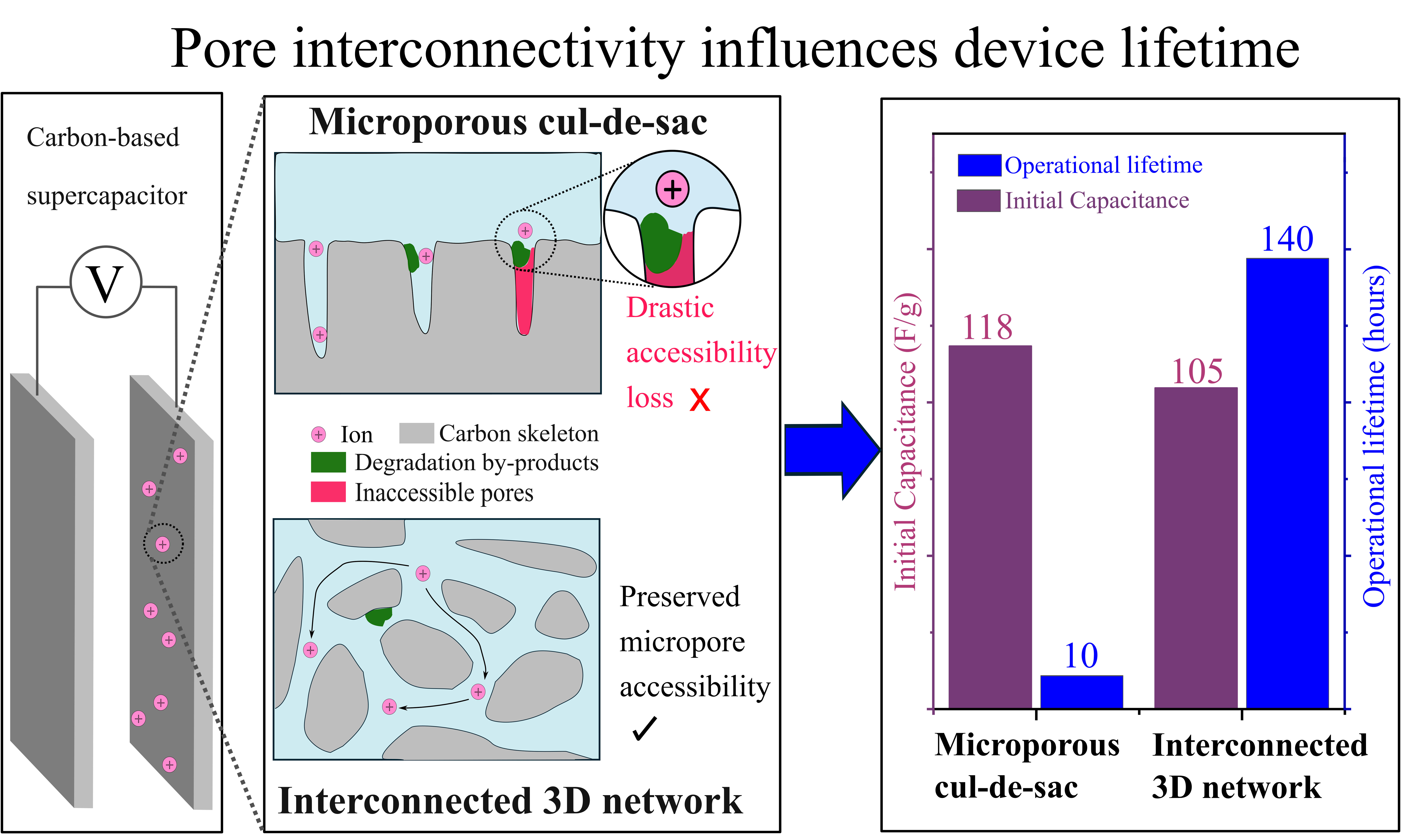
The occlusion of sorption sites during gradual electrochemical degradation is widely implicated in the capacitance fade of carbon-based supercapacitors, yet how pore architecture influences the tolerance of electrodes to pore blocking remains insufficiently studied. This work demonstrates that pore interconnectivity plays a key role in determining the tolerance of carbon electrodes to site occlusion. Alongside electrochemical tests, structural characterization of conventional activated carbons revealed how their narrow micropores are susceptible to accessibility loss while under potentiostatic operation, thus suffering rapid capacitance losses and equivalent series resistance (ESR) increments. In contrast, a carbon developed with a well-interconnected micro-mesoporous network demonstrated up to 14-fold longer lifetime under identical conditions. Critically, this improved durability translated to an 11-fold increase in cumulative energy delivered prior to End-of-Life of the device, as compared to carbons whose structures are initially optimized for maximizing capacitance. Further post-mortem analyses indicated that carbons with improved pore interconnectivity can tolerate a greater buildup of pore-blocking by-products before reaching capacitive failure, thus showing how pore network architecture mitigates or exacerbates the progressive occlusion of ion-accessible regions. We propose that highly interconnected pore structures feature alternative pathways that maintain the accessibility of sorption sites under constant operation. These findings establish pore interconnectivity as a key principle for extending the durability of supercapacitors under demanding voltage and temperature conditions.
Keywords
INTRODUCTION
Electrochemical double layer capacitors (EDLCs) are positioned as compact high-power energy storage solutions owing to their non-Faradaic charge storage mechanism within nanoporous carbon electrodes[1,2]. Although this working principle enables long operating lifetime and superior power densities, its relatively low energy densities compared to other energy storage devices remain a key limitation[2-6]. One strategy to overcome the limitations of EDLCs is to enhance their high-voltage stability to increase their rated operating voltage, which is fundamentally proportional to the energy density of the EDLC. However, prolonged high-voltage polarization is reported to accelerate parasitic electrochemical reactions at the electrode-electrolyte interface. These reactions are known to produce insulating solid-electrolyte-interphase (SEI) like layers and other byproducts such as organic compounds or evolved gases, which have been reported to progressively block pores and impede ion transport, leading to capacitance loss[7-10].
To address these issues, prior studies have primarily focused on developing electrolytes with wider electrochemical stability windows[7,11-14]. Although promising, this approach introduces significant trade-offs. Many high-voltage targeted electrolytes such as ionic liquids and sulfone-based solvents offer improved oxidative stability but often suffer from high viscosity, limited ion mobility, and significantly compromised performance at low temperatures[7,14]. These limitations translate to increased equivalent series resistance (ESR), reduced power density, and narrower operational flexibility. These limitations incentivize exploring new design principles for electrode materials so that EDLCs can be improved further to support a wider array of applications[15]. While specific surface area and pore size distribution are well-established metrics, emerging studies have clarified how tuning subtle network architectural features, such as ion path tortuosity and pore accessibility, influences an EDLC’s capacitance and rate performance[16-18]. Nevertheless, it remains unclear how architectural features such as pore interconnectivity affect device lifetime and degradation response.
In this work, we reveal that pore interconnectivity, defined by the availability of multiple transport pathways for ions to access sorption sites, is a key parameter that governs degradation behavior in EDLCs under sustained polarization. Structural characterization revealed that commercial micropore-dominant activated carbons, which have been engineered for high specific capacitance, display micropore channels that are vulnerable to site occlusion. Through accelerated electrochemical stress tests, our findings reveal how micropore-rich carbons deliver substantially lower discharged energy before operational failure, despite having higher initial capacitance. In contrast, carbons with high pore interconnectivity, as demonstrated by Scanning Isotherm Analysis, can extend the operating lifetime by up to 14-fold at 3 V and 70 °C, thereby enabling an 11-fold increase in cumulative energy discharge before operational failure. Further analysis using post-mortem energy-dispersive X-ray Spectroscopy (EDS), Raman spectroscopy, and pore size analysis revealed that well-interconnected carbons can accommodate more pore-blocking formation than conventional micropore-rich carbons before reaching similar End-of-Life states. This emphasizes how pore architecture governs the loss of ion transport pathways during gradual degradation. Our findings propose that highly interconnected structures, even in the presence of by-products, provide alternative pathways that allow ions to circumvent blocked regions and thereby retain capacitance. These findings underscore pore interconnectivity as a key design principle for durable EDLCs and suggest broader relevance to applications where sustaining efficient mass transport is essential.
MATERIALS AND METHODS
Materials acquisition
Three commercial activated carbons were purchased from their respective companies: ACS-PC (American Chemicals Supplier, USA), EL104 (Jacobi Carbon Group, Malaysia), and YP-80F (Kuraray Group, Japan). A fourth carbon, denoted as nanoporous amorphous carbon (NAC), was synthesized via the modified spark plasma sintering process (Type KCE®-FCT HHP D 25-SD, FCT Systeme GmbH, Germany), which was reported for developing amorphous carbons with an interconnected porous network[19]. Briefly, the starting precursor of Ketjenblack EC-600JD amorphous onion-like carbon (Lion Specialty Chemicals Co. Ltd, Japan) was first physically activated under CO2 gas (99.9% Pure, Leeden National Oxygen Ltd., Singapore) for 7 h at 1,000 °C to increase its porosity. Similar physical activation processes with CO2 gas have been used to broaden the pores of porous materials[20]. Then, 5 g of activated Ketjenblack powder was sintered via spark plasma sintering at 290 °C and 120 MPa for 30 min.
Materials characterization
Powder X-ray diffraction was conducted using the Bruker D8 Advance Diffractometer (Bruker, Germany) between 2θ values of 5° and 85° [Supplementary Figure 1A]. The scans were obtained at a 0.02 ° interval, with a scan rate of 0.2 s per point. Raman spectroscopy was performed at room temperature using a Horiba LabRAM HR Evolution microscope (Horiba France SAS, France). The Raman spectra were acquired using a 514 nm excitation laser focused via a 100× objective lens, resulting in a laser spot size of 1 μm, laser power of 0.5 mW, and total accumulation time of 30 s [Supplementary Figure 1B].
To comprehensively elucidate each carbon’s pore structure in the micropore and mesopore domains, a combination of CO2 physisorption measurements (Autosorb 6300 PFE XR-XR, Anton Paar, USA) and N2 physisorption measurements (Autosorb-iQ C-XR XR, Quantachrome Instruments, USA) was employed. CO2 physisorption measurements were conducted at 0 °C, while N2 physisorption measurements were conducted at -196.15 °C. For each sorption measurement, samples were first degassed at 300 °C for 18 h. After degassing, isotherms for each carbon were obtained across the full pressure range: 0-1.0P0. For carbon isotherms with prominent hysteresis, scanning isotherms were obtained across three P/P0 ranges, 0-0.6P0, 0-0.8P0, and 0-1.0P0 (denoting full isotherm), to further elucidate the connectivity of the pore network[21-24]. To characterize carbon electrodes before and after electrochemical tests, samples were degassed at 70 °C for 18 h instead, to prevent degradation of the binder.
For post-mortem EDS analysis, positive and negative electrodes were first extracted from cells that had lost at least 20% of their capacitance at 1 A/g, and immersed separately in anhydrous propylene carbonate (Sigma Aldrich, Germany). This was done to leach off any excess salt that could remain trapped in the pore structure. Similar soaking approaches have been employed in the literature to investigate the state of electrodes after cycling tests[8,25]. SEM images were obtained using a JEOL JSM-6700F Field Emission Scanning Electron Microscope (FESEM, JEOL, Japan) fitted with an X-MaxN 150 EDS detector (Oxford Instruments, United Kingdom). An acceleration voltage of 5 kV was used to obtain EDS spectra. For each carbon, EDS spectra were obtained at five spots on each aged positive and negative electrode separately.
Electrode and coin cell fabrication
Aqueous-based electrode slurries were prepared by mixing 2 g of carbon with carboxymethyl cellulose (CMC Daicel 2200, Daicel Miraizu, Japan) and Polypropylene (denoted PP) (YA-6010, UNITIKA, Japan). Specifically, the weight ratio of carbon:CMC:PP was set to 90:4:6. Each slurry was then coated onto 25 µm-thick aluminum current collectors (Toyal Carbo, Toyal Aluminum K.K., Japan) with a target electrode coating thickness of approximately 75-85 µm, with mass loadings ranging between 3.5-5.2 mg/cm2 depending on the powder porosity (More details in Supplementary Table 1). Electrodes were dried overnight at 80 °C, punched into 16 mm diameter electrodes, and assembled into coin cells using CR2032 parts (Landt Instruments, USA) inside a DANVEC Glovebox (Vortex Prime, IT Technologies Pte Ltd, Singapore). The separator used was a Celgard 3501 type (Celgard, USA) with a thickness of 25 µm. For the electrolyte used in this study, 1.5 M of spiro-1,1′-bipyrrolidinium tetrafluoroborate (denoted SBPBF4) (Tokyo Chemical Industry, Japan) was mixed in anhydrous propylene carbonate (Sigma Aldrich, Germany). SBPBF4 was selected as the electrolyte salt because of the small sizes of SBP+ and BF4-, whose diameters have been reported to be approximately 0.42 nm[26] and 0.45 nm[27], respectively. This allows ions to access even the sub-nanometer micropores inside the nanoporous carbon electrodes[28].
Electrochemical evaluation
Electrochemical measurements were performed using the VSP-300 Potentiostat (Bio-Logic SAS, France). Each coin cell was charged to 2.5 V at 0.05 A/g for five cycles, followed by 3 V at 0.05 A/g for five cycles to facilitate electrolyte ion wetting and ion transport into microporous regions. Before stability tests, the initial capacitance (denoted C0) was measured by charging a cell to 3 V at 1 A/g followed by a 30-min potentiostatic hold before immediately discharging at 1 A/g. To accelerate the degradation process, this charge-hold-discharge sequence was repeated for 20 cycles per round in an oven maintained at 70 °C. After every round, corresponding to 10 h of cumulative float time, cells were allowed to cool at ambient temperature to reach thermal equilibrium before further measurements. The energy discharged per cycle and corresponding single electrode capacitance were obtained based on the area under the discharge curve, which was determined via the integration approach below:
From Equations 1 and 2, Vwindow is the full operating voltage window (fixed at 3 V for this study), t1 and t2 are the bounds of the discharge slope in seconds (s), I is the set current in mA, and m is the mass of the two electrodes. This integration approach was referenced from an extensive interlaboratory study that highlighted the importance of evaluating EDLCs using procedures that account for non-ideal behavior arising from significant Ohmic losses[29]. Coin cells were subjected to repeated 20-cycle stress rounds until they reached End-of-Life, defined by attaining ~ 20% capacitance loss. This is in accordance with industry standards to define an appropriate operating lifetime of supercapacitors under well-defined conditions[7,10]. To evaluate the energy throughput of the different cells, the discharge energy per cycle is summed from the beginning of the stress test to the End-of-Life time frame.
To elucidate changes in ion transport behavior during electrochemical operation, Electrochemical Impedance Spectroscopy (EIS) was also conducted every 10 h at room temperature. Nyquist plots were obtained over a frequency range between 100 kHz and 0.1 Hz, with a sinusoidal amplitude of 10 mV. EC-Lab (Version 11.71, Bio-Logic SAS, France) was used to analyze the high-frequency regime of the Nyquist plots with equivalent circuit modelling, to elucidate the degradation of ion transport as cells undergo electrochemical stress.
RESULTS AND DISCUSSION
Pore structure characterization of powders
The nitrogen physisorption technique was first employed to identify subtle network features that can influence their susceptibility to obstruction within EDLC electrodes. While Brunauer-Emmett-Teller (BET) surface area and pore size distribution are conventionally used to rationalize pore-to-ion size matching to optimize capacitance[30-33], these quantitative descriptors alone fail to capture subtle network connectivity effects or the presence of bottleneck regions that can affect ion accessibility under electrochemical stress. The presence of such non-trivial structural features is captured by an asymmetric adsorption-desorption behavior of N2 during the measurement, giving rise to different hysteresis profiles that unveil underlying pore topology[22,24]. To further interpret such hysteretic features, recent studies employing advanced percolation models have shown that in mesoporous structures such as silica and Vycor glass, the hysteresis of physisorption isotherms can be systematically analyzed through partial P/P0 scanning isotherms across different relative pressures. This approach provides valuable insights into pore connectivity and network effects beyond the information captured by a full isotherm[21-23].
Figure 1A displays the isotherms of the three commercial activated carbons, whereby all isotherms exhibited similar features in a steep uptake at low pressure and a gentle plateau for P/P0 > 0.4. These features are associated with a Type-I(b) isotherm[21], validating their identity as micropore-rich carbons (MRCs). CO2 physisorption measurements support the above interpretation, evident in the steep uptake of CO2 at low relative pressures, which is attributed to an abundance of sub-nanometer micropores [Supplementary Figure 2A and B]. Through Quenched Solids Density Functional Theory (QSDFT) analysis, narrow mesopores between 2-4 nm were detected [Supplementary Figure 2C], with YP-80F having the highest mesopore volume fraction among the three MRCs [Supplementary Figure 2D]. To elucidate the connectivity of the network, the hysteresis of each isotherm was analyzed, through which neither prominent hysteresis nor a steep cavitation-associated desorption slope (at P/P0 within 0.4-0.5) was observed. These insights enable the structures of ACS-PC, EL104 and YP-80F to be interpreted as networks with minimal delay from bottleneck effects. These suggestions would be consistent with the conventional depiction of a microporous carbon in prior literature[7], in which narrow terminal micropore branches extend from a broader main channel [Figure 1B].
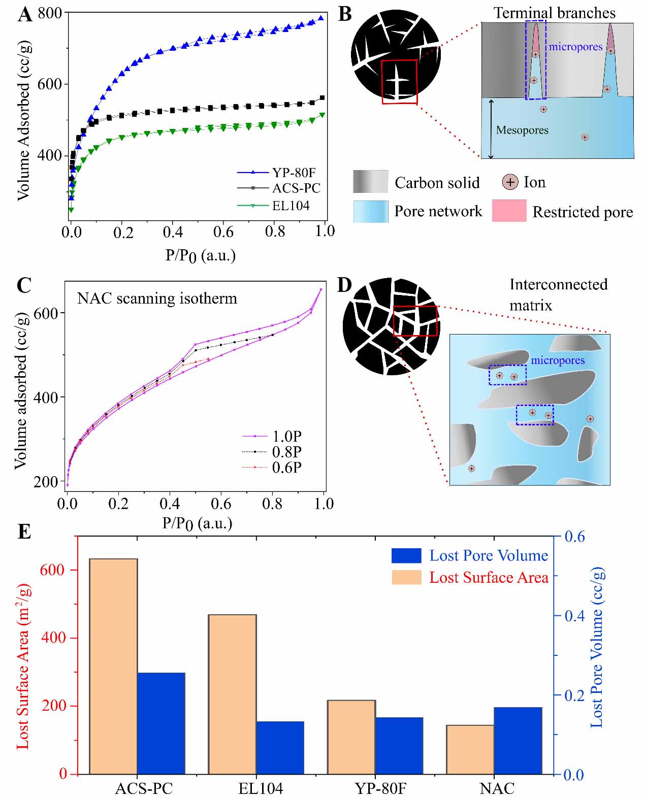
Figure 1. Gas physisorption analysis revealing distinct pore network architectures. (A) Standard nitrogen adsorption-desorption isotherms of EL104, YP-80F and ACS-PC, exhibiting Type I(b)-like behavior which is characteristic of micropore-rich carbons (MRCs); (B) Schematic interpretation of MRCs, highlighting micropore channels that extend from broader channels. Micropores and mesopores have been labelled to show their relative sizes; (C) Scanning isotherm array of NAC, due to its full-pressure range isotherm exhibiting a prominent hysteresis that sits between Type IV and Type H2 hysteresis; (D) Schematic interpretation of NAC’s pore structure based on its scanning hysteresis profile, suggesting a more interconnected network featuring micropores that can be accessed via multiple accessible pathways; (E) Quantifying lost surface area against lost pore volume incurred by each carbon after electrode fabrication through slurry processes. NAC: Nanoporous amorphous carbon.
Together with the pore-size distributions of the three MRCs [Supplementary Figure 2C and D], Figure 1A illustrates how pore-size broadening can be strategically employed to incorporate mesopores into a structure[20], which is critical for tuning the rate performance of EDLCs[30]. Although micropores enable solvated ions to undergo partial desolvation, thereby improving the ion packing of the double layer during charging[31,33], ion transport within narrow micropores is compromised due to high transport resistance[30]. In addition, some of these narrower pores could be smaller than the bare ion size and are thus inaccessible to ions (red-shaded area of Figure 1B). This can lead to underutilized surface area for charge storage[34]. To improve ion transport and increase the accessible surface area, physical or chemical activation methods that introduce additional larger pores such as mesopores have been utilized [Supplementary Figure 2E][20]. Through these approaches, the power performance of EDLCs can be enhanced[18,30,32]. In the following sections, the efficacy of the pore size broadening approach towards EDLC’s performance and cycling stability will be investigated by evaluating these carbons against a fourth non-conventional nanoporous amorphous carbon (hereafter denoted NAC) that was synthesized via a previously reported route designed to produce 3D-interconnected porous carbon matrices and volumetrically optimized pore structure[19].
Unlike the previously characterized MRCs, the full isotherm of NAC (Figure 1C, solid line) displayed a steeper N2 adsorption slope over P/P0 = 0.1-0.7, indicating the presence of mesopores with a broader pore-size distribution. The pore size distribution curve derived from QSDFT calculations
To further analyse the hysteretic profile of NAC, scanning isotherms were obtained (Figure 1C, black and red plots), and revealed two things: Firstly, none of the scanning isotherms collapsed into a near-vertical desorption slope towards the cavitation-characteristic pressure domain (P/P0 within 0.4-0.5), indicating that the desorption of gas is not fully driven by cavitation. Secondly, the scanning isotherms exhibited a loop whose area progressively decreased with lower P/P0 range, with their desorption slopes converging along the adsorption boundary rather than the desorption branch of the full-range isotherm. This observation suggests that the extent of hysteresis is dependent on the degree of prior pore filling of deeper network sites, indicating the influence of network-percolation effects. Given that NAC was previously reported to exhibit an intricate 3D-interconnected pore network that can be tuned through the spark plasma sintering process[19], these findings suggest that NAC exhibits a thoroughly percolated porous matrix [Figure 1D] rather than existing as isolated or terminating branches [Figure 1B].
Through physisorption characterization distinct differences in the pore structure of three commercial activated carbons versus that of a recently explored carbon were revealed, with some of their common quantitative metrics summarized in Supplementary Table 2. From these insights, we strove to rank the carbons based on their interconnectivity, which we previously defined as the degree to which microporous sites are accessible by multiple pathways. By this definition, when occlusive species are introduced into a porous network, a well-interconnected structure would mitigate the loss of pore accessibility much better than a poorly interconnected one. Therefore, to rank the carbons by their interconnectivity, the porosities of carbons before and after electrode fabrication were compared, because during the integration of binders and dispersant into the carbon slurry, some non-capacitive components may infiltrate the pore structure of the porous carbon matrix. This could lead to pore blocking even before device operation[25,35]. For a fair comparison, the electrode fabrication parameters were fixed such that the weight ratio of the porous carbon material to dispersant (CMC) to binder (PP) was set to 90:4:6.
Figure 1E summarizes the findings, notably showing that micropore-dominant ACS-PC incurred the largest surface area loss and pore volume loss after electrode formulation compared to the other carbons. By comparing the isotherms of each carbon’s pristine powder versus the electrode state after slurry fabrication [Supplementary Figure 3], it was also observed that ACS-PC’s isotherm showed a growth in the width of “low-pressure hysteresis” within P/P0 < 0.4, which can be attributed to sluggish desorption kinetics within extremely narrow channels such as ultra-micropores and small mesopores[18,21]. Since this growth of hysteresis was absent in the other three carbons, it suggests that after the slurry process, ACS-PC’s pore structure transitioned to one with compromised pore accessibility. By juxtaposing this insight with ACS-PC’s initial non-hysteretic Type-I(b) isotherm and low average pore size [Supplementary Table 2], these observations highlight a susceptibility of such narrow architectures to pore occlusion, especially when pore domains have been engineered to narrow size domains.
EL104 and YP-80F exhibited a smaller surface area loss than ACS-PC, which can be attributed to their higher mesopore fractions that improve pore accessibility [Supplementary Tables 2 and 3]. Intriguingly, NAC exhibited the lowest surface area loss after electrode fabrication process despite having comparable pore volume losses to EL104 and YP-80F. This suggests that beyond the extent of introducing pore-blocking elements, pore network architecture could influence the degree to which local obstruction events propagate to network-level losses in surface area. This occlusion concept can be extended to rationalize the degradation mechanism of EDLCs since sustained polarization promotes parasitic reactions at the electrode-electrolyte interface, leading to the formation of by-products that accumulate within the pore network over time[7,8]. To test this hypothesis, these electrodes were subsequently used to fabricate coin cells for additional electrochemical tests. To fabricate EDLCs for this study, 1.5 M SBPBF4 in propylene carbonate was selected as the electrolyte, as it is widely used in commercial applications due to its high ionic conductivity and relatively environmentally benign nature.
Electrochemical characterization of amorphous carbon electrodes
To evaluate the degradation behavior of the four carbons, accelerated electrochemical stress tests were conducted as illustrated in Figure 2A. These electrochemical float tests consisted of galvanostatic charge-discharge (GCD) cycles, where each cycle incorporates a potentiostatic holding step at 3 V (also known as a ‘float test’) under a temperature of 70 °C. Unlike rapid cycling tests, employing a potentiostatic period for 30 min per cycle enables parasitic electrochemical reactions to proceed over prolonged periods per cycle, thereby capturing the intrinsic degradation behavior of the materials under realistic operating conditions[7,14].
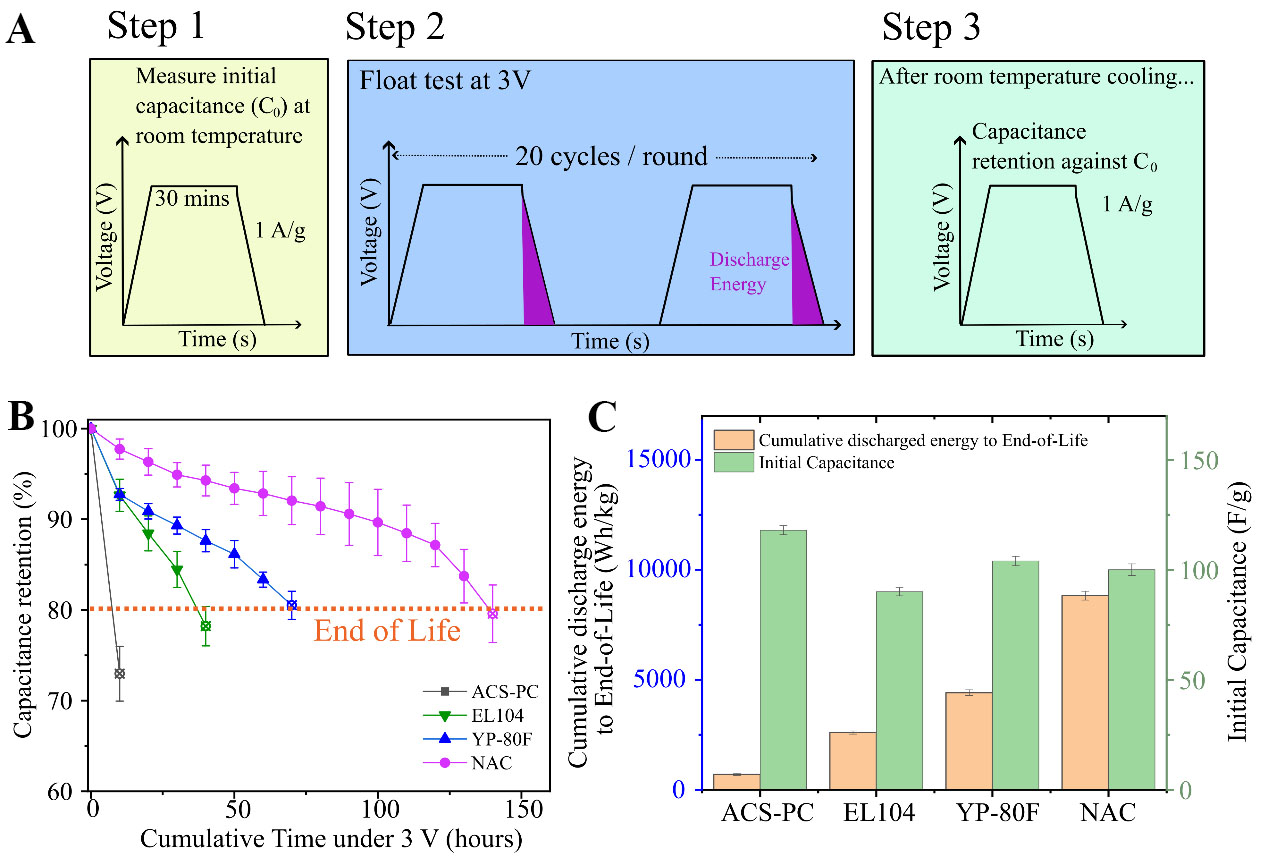
Figure 2. Accelerated electrochemical stress test protocol and its impact on capacitance retention and cumulative energy delivery. (A) Schematic for accelerated stress tests under 70 °C, involving a 30-min potentiostatic period (also known as a ‘float test’) at 3 V per cycle. The area under the discharge curve, including the IR Drop, was used to compute the discharge energy for each cycle; (B) Capacitance retention curves obtained in 10-h intervals, at room temperature. End-of-Life was determined based on losing approximately 20% of initial capacitance (dashed horizontal line). For each carbon, the performance of three individual cells can be found in Supplementary Materials, under Supplementary Tables 4-7. Error bars represent one standard deviation. NAC’s capacitance trend exhibited a gentle decay slope up until 120 h before decay accelerates. In contrast, YP-80F’s capacitance decay started to accelerate after 50 h; (C) Comparison of cumulative discharged energy up to End-of-Life alongside the initial capacitances of each carbon, measured at 3 V. Although ACS-PC exhibited superior initial capacitance, its rapid failure rate in comparison to those of carbons with developed mesoporosity highlights a trade-off between expanding theoretical capacitive limits and compromising throughput. The error bars represent one standard deviation, derived from the performance of three individual cells per carbon. NAC: Nanoporous amorphous carbon.
Initial capacitance measurements revealed ACS-PC’s superior gravimetric performance among the other three carbons [Supplementary Table 8]. However, the capacitance values did not scale directly with the carbon’s BET surface area. This discrepancy is evident in NAC’s comparable capacitance to YP-80F, despite NAC having a significantly lower surface area. To quantitatively visualize this discrepancy, the gravimetric capacitance of each carbon was divided by its characteristic BET surface area to estimate a surface area utilization metric. [Supplementary Table 8] Firstly, it was revealed that NAC exhibited the highest surface-area utilization among the four carbons. In addition, YP-80F exhibited the lowest surface-area utilization metric, despite having the highest surface area. These findings suggest that simply increasing the surface area cannot guarantee volumetrically efficient ion-sorption.
Figure 2B compares the degradation trajectory of each carbon’s capacitance in 10-h intervals. After the first 10-h potentiostatic round, ACS-PC’s capacitance faded significantly quicker than all other carbons, already surpassing the End-of-Life threshold of approximately 20% capacitance loss, a benchmark commonly applied across the industry[7,10]. In contrast, other carbons retained above 90% of their capacitance [Supplementary Table 8] and reached End-of-Life at much later time frames. For YP-80F and EL104, improvements in operating lifetime appeared consistent with increased mesopore fraction, suggesting that the integration of more and/or wider mesopore junctions facilitates ion transport as electrochemical degradation ensues. However, NAC exhibited improved capacitance retention than YP-80F, despite NAC’s lower total porosity. Intriguingly, the operating lifetime agreed with the interconnectivity ranking demonstrated in Supplementary Table 3. NAC, which ranked first in interconnectivity among this sample set, reached End-of-Life after 140 h, the longest duration observed in this study. The remaining carbons followed the order of YP-80F, EL104, and ACS-PC in decreasing lifetime and interconnectivity. This suggests that beyond simply increasing mesoporosity, there are other factors that can influence the degradation behavior of carbon electrodes under electrochemical stress.
To elucidate the practical implications of the trade-off between enhanced capacitance in microporous materials and their compromised lifetime, Figure 2C compares the cumulative energy delivered before End-of-Life with the initial capacitance of each carbon. In summary, Figure 2C shows that the enhancement of capacitance displayed by ACS-PC failed to translate to improved long-term energy output because of its rapid device failure and low cycle count. In contrast, carbons with balanced porosities and interconnected networks sustained energy delivery across much longer operating periods. Specifically, NAC enabled up to an 11-fold increase in overall energy output as compared to micropore-dominant ACS-PC. Even relative to YP-80F, which has incorporated substantial mesoporosity, NAC exhibited nearly a two-fold increase in operating lifetime and energy output despite exhibiting lower surface area and lower porosity than YP-80F. These findings suggest that rather than bulk porosity metrics alone, the organization of the micropores and mesopores is critical to improving the accessibility of microporous sites.
To complement the insights obtained from potentiostatic stress tests, electrochemical impedance spectroscopy (EIS) was employed to elucidate how ion transport in different carbon electrodes is compromised during prolonged electrochemical operation. Prior to stress testing, each carbon’s Nyquist plot displayed varying sizes of the high-frequency semicircle regime. By using an equivalent circuit model [Supplementary Figure 4], the real-axis span of the semicircle can be attributed to the resistance that ions experience when moving into the pore structure[36]. This will be hereafter denoted as Raccess and is thus a quantitative proxy for how difficult it is for ions to access the internal network. It was observed that Raccess correlated with the micropore fraction of the carbons [Supplementary Table 9], and since the electrolyte used for all carbon EDLCs was standardized, it suggests that Raccess correlates to ion transport kinetics that are dependent on pore-network dimensions. Indeed, similar associations have been made in elucidating how larger pores such as mesopores serve a critical role in facilitating ion transport and ESR optimization[30,32].
After the first 10 h of the stress test, ACS-PC exhibited a pronounced right shift along the x-axis alongside a growth of the high-frequency semicircle region (Figure 3A, from R to R2). The latter feature has been associated with the resistance that arises from ion transport limitations[14]. In addition, there was a significant increase in ESR1kHz (from 1.33 Ohm to 1.94 Ohm), which is consistent with the rapid capacitance decay observed from the GCD measurements. With the other MRCs, similar increases in ESR1kHz (from 0.96 Ohm to 1.52 Ohm) and Raccess were observed for EL104 after the first 10 h [Figure 3B]. In contrast, YP-80F’s Nyquist plot exhibited less pronounced distortion after 10 h [Figure 3C], suggesting that transport limitations incurred more gradually in carbons with more mesopores. Nevertheless, EL104 and YP-80F exhibited significant distortions in the form of increased semicircle diameter and a right x-shift as they approached End-of-Life at 40 and 70 h, respectively.
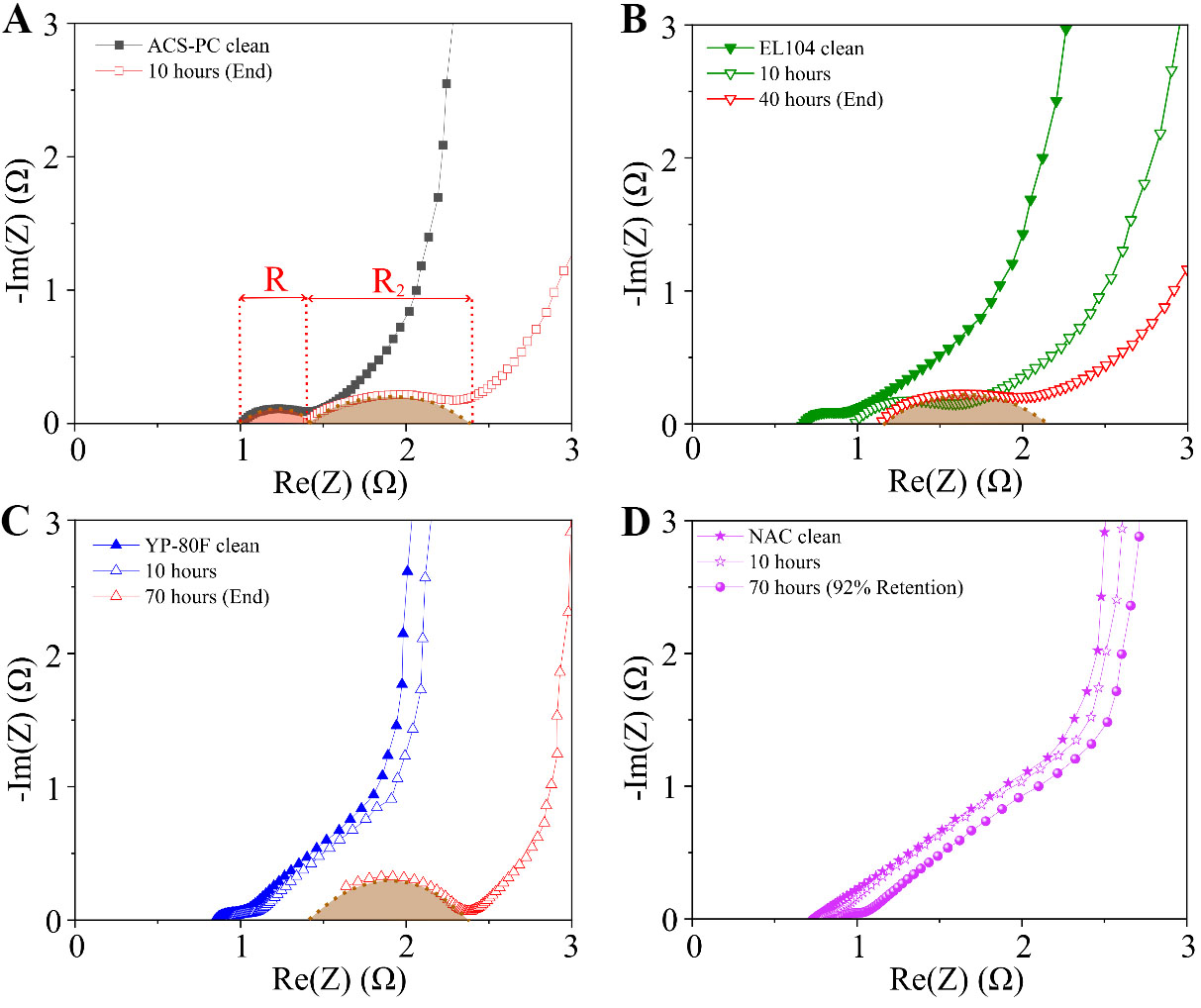
Figure 3. Nyquist plot comparisons reveal compromised high-frequency response, especially in micropore-dominant carbons. (A-C) Nyquist plot comparisons for ACS-PC, EL104, and YP-80F respectively. After 10 h of testing, ACS-PC’s Nyquist plots showed a prominent growth of the high-frequency semicircle region. R and R2 represent the derived Raccess values from equivalent circuit modelling, before and after aging. Similarly, EL104 and YP-80F exhibited prominent increases in Raccess at later time frames; (D) Nyquist plot array for NAC: The clean and 10-h Nyquist plots were selected to compare its behavior to all commercial carbons, while the Nyquist plot at the 70-h mark was chosen to benchmark against that of YP-80F specifically. After 70 h of testing, NAC retained 92% capacitance, and unlike the other carbons, NAC’s Nyquist plots had a significantly smaller high-frequency semicircle. NAC: Nanoporous amorphous carbon.
In contrast to the three MRCs, NAC exhibited only minor distortions in its Nyquist plot [Figure 3D]. Even after 70 h, its impedance response showed only a minor right shift in the x-axis and limited development of the high-frequency semicircle as compared to YP-80F. Given the similar mesopore volume exhibited by YP-80F and NAC [Supplementary Table 2], the observations suggest that the organization of mesopores within NAC more effectively mitigates the degradation of ion transport that is accelerated by sustained high-voltage polarization. This supports the view that network architecture, rather than overall porosity and surface area, governs the extent to which degradation translates to the loss of ion-accessible pathways. To further determine whether network architecture plays an active role in dictating long-term device performance, post-mortem analyses were subsequently performed.
Post-mortem analyses of aged carbon electrodes
Raman spectra of vacuum-dried End-of-Life carbon electrodes were compared against their pristine counterparts (prior to coin cell assembly), to deduce whether the carbon framework underwent significant structural transformation [Supplementary Figure 5]. Across all four carbons, there were no pronounced changes in the Raman spectra, indicating that there was no noticeable transformation of the carbon framework. However, the absence of a strong Raman change does not exclude degradation within the electrochemical cell. In this regard, we considered that for propylene carbonate-based EDLCs, its electrochemical degradation has been reported to produce oxygen-containing species such as poly(propylene carbonate) and propylene glycol. These species can contribute to measurable oxygen signals under EDS analysis[8]. Thus, post-mortem analyses were conducted to elucidate the elemental composition of carbon electrode pairs that exhibited a similar extent of capacitance losses (-20%).
Firstly, comparisons of SEM images [Supplementary Figures 6-9] before and after float tests show no noticeable morphological changes across all electrodes. Despite this, post-mortem SEM/EDS analyses of each carbon electrode pair revealed increased oxygen fractions across all carbons [Figure 4A]. Notably, NAC’s positive electrode showed significantly more oxygen enrichment than the other carbons. Given that this is consistent with its significantly enhanced lifetime compared to all other micropore-rich carbons (MRCs), the findings suggest that NAC’s interconnected pore structure can tolerate a greater amount of oxygen-containing, pore-blocking by-products before reaching similar extents of capacitance loss.
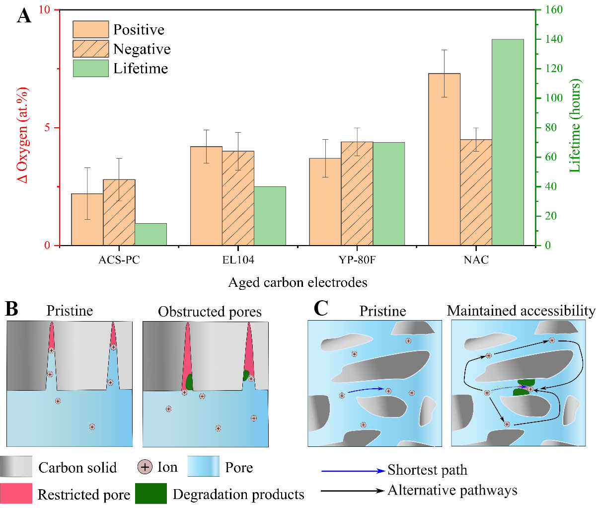
Figure 4. Post-mortem analyses and schematic discussion of degradation tolerance. (A) EDS analyses of aged carbon electrodes to elucidate the changes in oxygen composition of the electrode after attaining End-of-Life (defined by 20% capacitance loss). Each carbon is also plotted against its lifetime. For the chart derived via EDS analyses, the error bars correspond to one standard deviation and represent the variability in composition within each aged electrode. Five spots were measured per electrode; (B) Schematic of premature pore occlusion inside micropore-rich structures with terminal branches. Local obstructions at pore entrances lead to a loss of ion accessibility; (C) Schematic of mitigated pore blocking within well-interconnected pore structures. Despite the accumulation of by-products, alternative pathways allow ions to migrate across the structure, leading to mitigated capacitive loss and subsequently enhanced cycling lifetime. EDS: Energy-dispersive X-ray spectroscopy.
To support the interpretation of EDS findings, further physisorption measurements of aged electrodes were obtained for NAC and YP-80F [Supplementary Figure 10A-D] to examine the electrode’s pore structure after the same duration of electrochemical stress. Specifically, the states of YP-80F and NAC electrodes at the 70-h mark are compared, because that was when their capacitance retention curves began to diverge. The isotherms of YP-80F electrodes displayed a significant reduction in overall Nitrogen uptake after stress tests, indicating a loss of pore accessibility [Supplementary Figure 10A]. Further analysis of pore size distributions corroborated these findings, showing that the population of micropores and mesopores distinctly decreased after 70 h of testing [Supplementary Figure 10B]. On the other hand, the isotherms of NAC electrodes showed a much smaller reduction in overall Nitrogen uptake after cycling for the same duration [Supplementary Figure 10C]. In addition, the pore size distribution curves of NAC electrodes only showed minor reductions after 70 h of floating [Supplementary Figure 10D]. By considering that YP-80F’s lifetime was lower despite having overall higher porosity, the above insights indicate that under the same degree of electrochemical stress, the degree of pore accessibility loss can be mitigated through factors beyond total pore volume.
To discuss the divergence in capacitive failure, mechanistic interpretations of how different pore structures respond to degradation mechanisms are proposed in Figure 4B and C. Figure 4B schematically displays how pore networks featuring terminal branches, such as the three commercial activated carbons in this study, are vulnerable to rapid capacitive failure. Prior to any electrochemical degradation, these structures feature access to microporous sorption sites through a single pore entrance. Owing to the isolated nature of these regions, the deeper parts of the micropore branch would be inaccessible for ion sorption (denoted in the red area of Figure 4B). As the cell is subject to potentiostatic operation, degradation by-products generated from parasitic reactions propagate across the network and may accumulate at pore entrances. With no alternative pathways to access these sorption sites, the gradual narrowing of the pore entrance compromises ion transport due to inhibited kinetics and can eventually reach a state of complete pore occlusion, leading to catastrophic reductions in accessible surface area and subsequent capacitance loss.
In contrast, Figure 4C shows how NAC exhibits a three-dimensional percolated mesoporous network as evidenced by its scanning isotherms and TEM tomography from our earlier study[19], confirming its fully interconnected structure. This pore architecture provides multiple entry and exit pathways for ions, enabling efficient ingress and egress throughout the porous network. Even as by-products accumulate at critical pore entrances and block off certain areas, several sorption sites remain accessible to ions through alternative, more tortuous routes. As a result, NAC exhibits high surface area utilization and mitigates capacitance losses more effectively than poorly percolated carbons. Collectively, these results demonstrate that pore interconnectivity, rather than pore size or total pore volume, is a crucial factor governing ion accessibility, SEI tolerance, and long-term electrochemical stability in EDLC electrodes.
Demonstrating cycling stability in an alternate sulfone-based electrolyte system
To verify that the insights drawn can be applied beyond the propylene-carbonate system, the same accelerated stress protocol (3 V and 70 °C) was also conducted in a sulfone-based electrolyte (specifications listed in
Notably, micropore-dominant ACS-PC still exhibited a rapid drop of capacitance retention before the 10-h mark. This indicates that cycling stability was not noticeably improved, despite switching to a more electrochemically stable electrolyte system. This highlights the importance of tailoring the electrode architecture to complement existing strategies focused on electrolyte engineering, thereby affirming electrode-electrolyte synergy and expanding the operating limits of supercapacitors. Collectively, these observations support the broader applicability of pore interconnectivity as a design principle beyond a single electrolyte chemistry.
CONCLUSION
This study showcases how pore network interconnectivity is critical to developing EDLCs with high capacitance retention under sustained polarization. By systematically comparing carbons with different pore structures under controlled aging conditions, we showed that carbons with well-interconnected networks can mitigate capacitance loss by featuring alternative paths to access sorption sites, thereby circumventing blocked channels. Further research can explore the development of combining pore structure engineering with disorder tuning in nanoporous carbons to achieve highly efficient charge storage. In addition, the advantages of a well-interconnected pore hierarchy can be explored in other areas such as carbon capture and catalysis, where the transport of media within tortuous porous systems is critical for their applications.
DECLARATIONS
Authors’ contributions
Made substantial contributions to conception and design of the study and performed data analysis and interpretation: Ozyilmaz, B.; Limpo, C. M. A.; Lee, J. H.
Performed data acquisition and provided administrative, technical, and material support: Ong, Y. K.; Sassi, L. M.; Rao, Y.; Shi, L.; Poh, E. T.; Tsuchiya, K.; Takahashi, D.
Availability of data and materials
The original contributions presented in this study are included in the article/Supplementary Materials. Further inquiries can be directed to the corresponding authors.
AI and AI-assisted tools statement
During the preparation of this manuscript, the AI tool ChatGPT (version 5.5, released 2026-04-23) was used solely for language editing. The tool did not influence the study design, data collection, analysis, interpretation, or the scientific content of the work. All authors take full responsibility for the accuracy, integrity, and final content of the manuscript.
Financial support and sponsorship
This work was supported by the National Research Foundation, Prime Minister’s Office, Singapore, under its Competitive Research Programme (CRP award number NRF-CRP22-2019-008) and Medium-Sized Centre Programme (CA2DM), by Ministry of Education of Singapore, under its Research Centre of Excellence award to the Institute for Functional Intelligent Materials (I-FIM, Project No. EDUNC-33-18-279-V12), and by EDB Singapore, under its Space Technology Development Programme (S22-19013-STDP), and by the National Research Foundation, Agency for Science, Technology and Research (A*STAR) under its RIE2025 Urban Solutions and Sustainability (USS) LCER Phase 2 Programme 1st Emerging Technology Grant Call (Award No. U2411D4008).
Conflicts of interest
Tsuchiya, K.; Takahashi, D. are affiliated with Youth Engineering Co. Ltd., while the other authors have declared that they have no conflicts of interest.
Ethical Approval and Consent to Participate
Not applicable.
Consent for publication
Not applicable.
Copyright
© The Author(s) 2026.
Supplementary Materials
REFERENCES
1. Şahin, M.; Blaabjerg, F.; Sangwongwanich, A. A comprehensive review on supercapacitor applications and developments. Energies 2022, 15, 674.
2. Yuan, H.; Hua, J.; Wei, W.; Zhang, M.; Hao, Y.; Chang, J. Progress and prospect of flexible MXene‐based energy storage. Carbon. Energy. 2025, 7, e639.
3. Yun, Y.; Nandanapalli, K. R.; Choi, J.; Son, W.; Choi, C.; Lee, S. Extremely flexible and mechanically durable planar supercapacitors: High energy density and low-cost power source for E-skin electronics. Nano. Energy. 2020, 78, 105356.
4. Malkawi, A. M.; Alawneh, M. I.; Bashaireh, A. A seamless start-up for a hybrid uninterruptible power supply based on a diesel generator and supercapacitor energy storage. Results. in. Engineering. 2024, 24, 103418.
5. Yadlapalli, R. T.; Alla, R. R.; Kandipati, R.; Kotapati, A. Super capacitors for energy storage: Progress, applications and challenges. J. Energy. Storage. 2022, 49, 104194.
6. Singh, N.; Singh, V.; Bisht, N.; et al. A comprehensive review on supercapacitors: Basics to recent advancements. J. Energy. Storage. 2025, 121, 116498.
7. Pameté, E.; Köps, L.; Kreth, F. A.; et al. The many deaths of supercapacitors: degradation, aging, and performance fading. Adv. Energy. Mater. 2023, 13, 2301008.
8. Ishimoto, S.; Asakawa, Y.; Shinya, M.; Naoi, K. Degradation responses of activated-carbon-based EDLCs for higher voltage operation and their factors. J. Electrochem. Soc. 2009, 156, A563.
9. He, M.; Fic, K.; Fra̧ckowiak, E.; Novák, P.; Berg, E. J. Ageing phenomena in high-voltage aqueous supercapacitors investigated by in situ gas analysis. Energy. Environ. Sci. 2016, 9, 623-33.
10. Teuber, M. Lifetime assessment and degradation mechanisms in electric double-layer capacitors. Dissertation, RWTH Aachen University, Institute for Power Electronics and Electrical Drives, Germany, 2019. https://publications.rwth-aachen.de/record/771314/files/771314.pdf.
11. Chiba, K.; Ueda, T.; Yamaguchi, Y.; Oki, Y.; Shimodate, F.; Naoi, K. Electrolyte systems for high withstand voltage and durability i. linear sulfones for electric double-layer capacitors. J. Electrochem. Soc. 2011, 158, A872.
12. Van, T. Nguyen H, Chan Kim B, Thet MZ, Lee K. Pushing the boundaries of supercapacitor stability: a sulfone-based electrolyte for harsh operating conditions. J. Power. Sources. 2026, 666, 239128.
13. Wang, Y.; Xing, L.; Li, W.; Bedrov, D. Why do sulfone-based electrolytes show stability at high voltages? J. Phys. Chem. Lett. 2013, 4, 3992-9.
14. Köps, L.; Kreth, F. A.; Leistenschneider, D.; et al. Improving the stability of supercapacitors at high voltages and high temperatures by the implementation of ethyl isopropyl sulfone as electrolyte solvent. Adv. Energy. Mater. 2023, 13, 2203821.
15. Dissanayake, K.; Kularatna-abeywardana, D. A review of supercapacitors: materials, technology, challenges, and renewable energy applications. J. Energy. Storage. 2024, 96, 112563.
16. Vasilyev, O. A.; Kornyshev, A. A.; Kondrat, S. Connections matter: on the importance of pore percolation for nanoporous supercapacitors. ACS. Appl. Energy. Mater. 2019, 2, 5386-90.
17. Kress, T.; Liu, X.; Forse, A. C. Pore network tortuosity controls fast charging in supercapacitors. Nat. Mater. 2026, 25, 440-6.
18. Castro-gutiérrez, J.; Jagiello, J.; Celzard, A.; Fierro, V. Introducing a novel Hierarchy-Connectivity factor for characterizing micro-mesoporous materials. Chem. Eng. J. 2024, 497, 154938.
19. Lee, J. H.; Loh, N. D.; Yeo, Z. Y.; et al. Engineering a hierarchy of disorder: a new route to synthesize high-performance 3D nanoporous all-carbon materials*. Adv. Mater. 2024, 36, e2402628.
20. Li, L.; Sun, F.; Gao, J.; Wang, L.; Pi, X.; Zhao, G. Broadening the pore size of coal-based activated carbon via a washing-free chem-physical activation method for high-capacity dye adsorption. RSC. Adv. 2018, 8, 14488-99.
21. Thommes, M.; Kaneko, K.; Neimark, A. V.; et al. Physisorption of gases, with special reference to the evaluation of surface area and pore size distribution (IUPAC Technical Report). Pure. Appl. Chem. 2015, 87, 1051-69.
22. Kube, S. A.; Turke, K.; Ellinghaus, R.; Wallacher, D.; Thommes, M.; Smarsly, B. M. Pore size gradient effect in monolithic silica mesopore networks revealed by in-situ SAXS physisorption. Langmuir 2020, 36, 11996-2009.
23. Schlumberger, C.; Thommes, M. Characterization of hierarchically ordered porous materials by physisorption and mercury porosimetry - a tutorial review. Adv. Mater. Inter. 2021, 8, 2002181.
24. Söllner, J.; Neimark, A. V.; Thommes, M. Development and application of an advanced percolation model for pore network characterization by physical adsorption. Langmuir 2024, 40, 23146-68.
25. Pourhosseini, S.; Bothe, A.; Balducci, A.; Beguin, F.; Ratajczak, P. Strategy to assess the carbon electrode modifications associated with the high voltage ageing of electrochemical capacitors in organic electrolyte. Energy. Storage. Mater. 2021, 38, 17-29.
26. Yu, X.; Wang, J.; Wang, C.; Shi, Z. A novel electrolyte used in high working voltage application for electrical double-layer capacitor using spiro-(1,1′)-bipyrrolidinium tetrafluoroborate in mixtures solvents. Electrochimica. Acta. 2015, 182, 1166-74.
27. Jäckel, N.; Rodner, M.; Schreiber, A.; et al. Anomalous or regular capacitance? J. Power. Sources. 2016, 326, 660-71.
28. Kim, M.; Kim, S. Electrochemical properties of non-aqueous electrolytes containing spiro-type ammonium salts. J. Ind. Eng. Chem. 2014, 20, 4447-51.
29. Gittins, J. W.; Chen, Y.; Arnold, S.; et al. Interlaboratory study assessing the analysis of supercapacitor electrochemistry data. J. Power. Sources. 2023, 585, 233637.
30. Zhao, J.; Jiang, Y.; Fan, H.; et al. Porous 3D few-layer graphene-like carbon for ultrahigh-power supercapacitors with well-defined structure-performance relationship. Adv. Mater. 2017, 29, 1604569.
31. Chmiola, J.; Yushin, G.; Gogotsi, Y.; Portet, C.; Simon, P.; Taberna, P. L. Anomalous increase in carbon capacitance at pore sizes less than 1 nanometer. Science 2006, 313, 1760-3.
32. Xu, J.; Yuan, N.; Razal, J. M.; et al. Temperature-independent capacitance of carbon-based supercapacitor from -100 to 60 °C. Energy. Storage. Mater. 2019, 22, 323-9.
33. Qing, L.; Long, T.; Yu, H.; et al. Quantifying ion desolvation effects on capacitances of nanoporous electrodes with liquid electrolytes. Chem. Eng. Sci. 2021, 240, 116662.
34. Nair, M. R.; Chandran, A. S.; Shukla, N.; Prajapati, V. K.; Roy, T. Impact of ion geometry and electrode pore interconnectivity on charge storage and dynamics in confined nanopores. Advcd. Theory. and. Sims. 2026, 9, e02219.
35. Im, J.; Liu, X.; O'Keefe, C. A.; Grey, C. P.; Forse, A. C. Pore-intrusion of polymeric binder in supercapacitor electrodes decreases capacitance. Nanoscale 2026, 18, 11880-9.
Cite This Article
 Open Access
How to Cite
Download Citation
Export Citation File:
Type of Import
Tips on Downloading Citation
Citation Manager File Format
Type of Import
Direct Import: When the Direct Import option is selected (the default state), a dialogue box will give you the option to Save or Open the downloaded citation data. Choosing Open will either launch your citation manager or give you a choice of applications with which to use the metadata. The Save option saves the file locally for later use.
Indirect Import: When the Indirect Import option is selected, the metadata is displayed and may be copied and pasted as needed.
About This Article
Copyright

Data & Comments
Data
0










Comments
Comments must be written in English. Spam, offensive content, impersonation, and private information will not be permitted. If any comment is reported and identified as inappropriate content by OAE staff, the comment will be removed without notice. If you have any queries or need any help, please contact us at [email protected].