

Optimizing multiscale resin flow kinetics and impregnation uniformity in fiber-reinforced polymers composites via hierarchical carbon nanostructures
 0
0 Graphical Abstract
Abstract
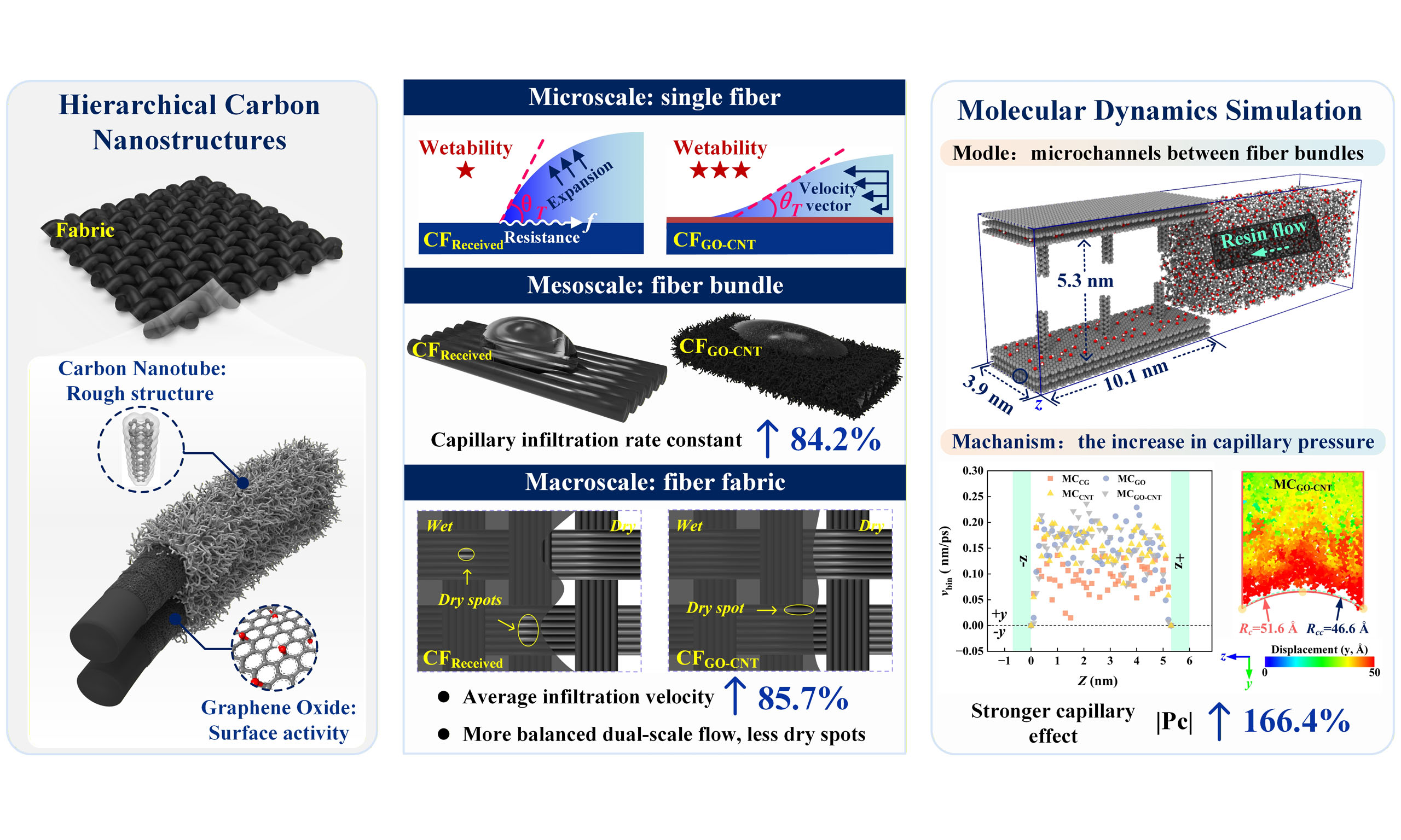
Resin flow dynamics and impregnation uniformity are critical factors governing the quality and manufacturing efficiency of carbon fiber-reinforced polymer (CFRP) composites fabricated by liquid composite molding (LCM). To address these challenges, a hierarchical three-dimensional carbonaceous nanostructure was constructed on carbon fiber surfaces. This architecture was designed to enhance resin impregnation across multiple scales: single fibers at the microscale, fiber bundles at the mesoscale, and fiber fabrics at the macroscale. Experimental results showed that the hierarchical structure significantly improved the wettability of the carbon fibers, reducing the contact angle from 50.65° to 34.95°. Meanwhile, the capillary infiltration rate constant of the fiber bundles and the average resin infiltration velocity through the fabric increased by 84.2% and 85.7%, respectively. The enhanced intra-bundle infiltration reduced the velocity mismatch between intra-bundle and inter-bundle flows, thereby improving the overall uniformity of resin impregnation. Moreover, molecular dynamics (MD) simulations were performed to elucidate the underlying infiltration mechanisms. The simulations revealed that the hierarchical structure increased the magnitude of the capillary pressure within the microchannels by 166.4%, leading to enhanced capillary-driven resin transport. Importantly, the nanostructured interface promoted molecular-chain migration within the microchannels by modifying solid-liquid interactions, thereby facilitating resin infiltration within the fiber bundles.
Keywords


 Download PDF
INTRODUCTION
The rapid growth of high-performance sectors, including aerospace, marine engineering, civil infrastructure, and energy, has intensified the demand for advanced materials that combine high strength and stiffness with low density, cost-effectiveness, and sustainability. In this context, carbon fiber-reinforced polymer (CFRP) composites have attracted increasing attention.
To meet the stringent application requirements, extensive efforts have been devoted to modifying the resin matrix and fiber surfaces of CFRP laminates[1]. In recent years, surface-engineering strategies based on nanomaterials[2-4], particularly one-dimensional (1D) and two-dimensional (2D) carbon-based nanomaterials[5,6], have shown considerable promise. Hybrid modification strategies integrating different nanomaterials can produce synergistic effects[7-9], thereby simultaneously improving the mechanical, thermal, and electromagnetic properties of CFRPs. These advances have strengthened the competitiveness of CFRPs in demanding engineering applications, where performance and reliability beyond those of conventional structural materials are critical[10]. For example, in our recent work[11], a three-dimensional (3D) graphene oxide-carbon nanotube (GO-CNT) nanostructure was constructed in situ on carbon fiber (CF) surfaces and was shown to improve the damping performance of CFRPs without compromising their mechanical integrity. However, realizing the full potential of such materials still requires a well-controlled and efficient manufacturing process. Therefore, beyond performance optimization, the processing behavior of CFRPs warrants equal attention.
Liquid composite molding (LCM) is a widely used manufacturing process for CFRPs that enables the production of geometrically complex, near-net-shape components[12]. In a typical LCM process, a fiber preform is placed in a rigid mold, and the resin is injected through pre-designated gates under pressure gradients to infiltrate the porous preform and displace the entrapped air[13]. Thus, process control requires a thorough understanding of mold-filling dynamics to ensure complete impregnation of the reinforcement and resin penetration into both inter-bundle channels and intra-bundle pores.
During the mold-filling stage, the multiscale pore structure of fiber preforms can induce nonequilibrium resin flow, commonly known as the dual-scale effect. This phenomenon arises from the competition between macroscale resin flow through inter-fiber bundles, which is dominated by viscous forces, and microscale infiltration through intra-fiber bundles, which is strongly influenced by capillary forces[14]. Such nonequilibrium flow is governed by the resin properties (e.g., viscosity and surface tension), fabric architecture, and processing parameters, all of which critically impact component quality and manufacturing efficiency[15,16]. Fiber surface morphology and textile architecture influence in-plane permeability by altering the geometry of mesoscopic channels that guide resin flow[17,18]. Surface modification with carbon nanomaterials can further enhance wettability by introducing polar functional groups and forming nanoscale capillary networks[19-21]. For instance, GO deposition has been reported to reduce the contact angle from 72° to 43° and increase the surface energy from 35.3 to 56.7 mJ/m2[22], whereas CNT growth reduced the contact angle of epoxy resin from 78° to 38°[23]. The distinctive 3D curvature of CNTs alters the local solid-liquid interfacial geometry and wetting behavior, promoting microscale resin transport[24,25].
Despite their localized benefits, nanomaterials can introduce inconsistencies in behavior across multiple length scales. Carbonaceous coatings can alter pore morphology and distribution[26-28], hence complicating the assessment of processing behavior. Notably, enhancements at the microscale do not necessarily translate into proportional improvements in performance at the mesoscopic or macroscopic scale. At the macroscale, resin flow is generally driven by pressure gradients and described by Darcy’s law, whereas microscale transport is governed by capillary forces[29]. The addition of nanofillers may reduce the effective pore volume, potentially diminishing capillary pressure gradients and impeding overall permeability[30,31]. Therefore, elucidating the multiscale flow mechanisms in nanostructured fiber preforms is essential for the scalable processing of high-performance CFRPs. This is an area that remains underexplored.
Herein, a 3D GO-CNT nanostructure was fabricated on CF surfaces via electrophoretic deposition (EPD) followed by ethanol flame treatment, aiming to enhance resin impregnation and improve flow behavior during LCM. The surface modifications were characterized using scanning electron microscopy (SEM) and X-ray photoelectron spectroscopy (XPS). Microscale wettability was evaluated through static contact angle measurements on individual fibers, and infiltration behavior was quantified using optical contact angle analysis and flow rate modeling. At the macroscale, the effect of the surface modification on resin impregnation in woven fabrics was evaluated using one-dimensional in-plane unsaturated flow experiments. Molecular dynamics (MD) simulations were further conducted to elucidate the mechanisms of flow enhancement within porous media.
EXPERIMENTAL WORK AND MD SIMULATION
Material fabrication
Commercial T300 CF fabrics (3K, plain weave, Toray, Japan) were refluxed in acetone for 48 h to remove the surface sizing. Multilayer GO (purity > 99%, 5-10 layers, diameter ~5-10 μm; Xiamen Knano, China) was deposited onto CFs by EPD under the processing parameters: GO concentration 0.25 g/L, applied voltage 10-25 V, deposition time of 10-25 min, solution pH of 10.0, and electrode spacing of 20 mm, all conducted in an ultrasonic bath. CNTs were subsequently grown in situ by ethanol flame pyrolysis, using Ni2+ ions (0.05-0.4 mol/L, derived from NiCl2·6H2O) as the catalyst precursor. The woven CF fabrics were exposed to an ~700 °C ethanol flame for 30-90 s in order to promote CNT growth. GO-CNT hybrid nanostructures were fabricated via sequential EPD (15 V, 15 min) and flame pyrolysis (0.4 mol/L Ni2+, 90 s), based on optimized carbon yield [Supplementary Figure 1]. The fiber surface modification procedures are illustrated in Figure 1. For clarity, untreated and desized fibers are denoted as CFReceived and CFDesized, respectively. The fibers modified with GO, CNT, and GO-CNT nanostructures are designated CFGO, CFCNT, and CFGO-CNT, respectively.
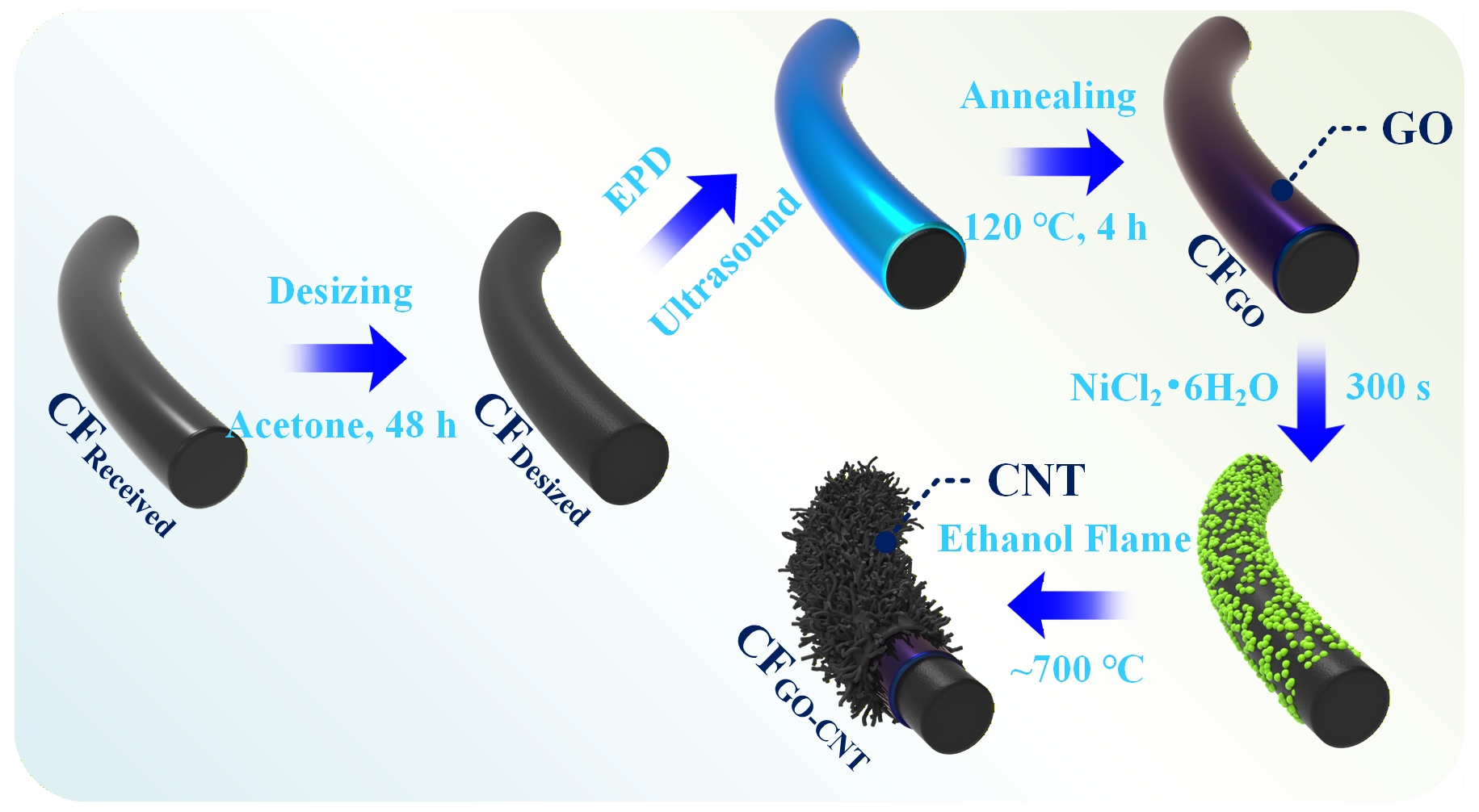
Figure 1. Schematic illustration of the design and fabrication process for carbon nanomaterial-modified CFs via EPD and ethanol flame synthesis. CF: Carbon fiber; EPD: electrophoretic deposition; GO-CNT: graphene oxide-carbon nanotube.
Experimental details
Microstructure and surface analysis of CFs
The surface morphologies of treated CFs were characterized using field-emission SEM (JSM-7600F, JEOL) operated at an accelerating voltage of 10 kV, following platinum sputter coating. Surface chemical composition was analyzed by XPS (Kratos Axis Supra+, Shimadzu) equipped with a monochromatic aluminum Kα X-ray source (1,486.6 eV). Measurements were recorded using a 300 × 700 μm2 spot size under an ultra-high vacuum of < 5 × 10⁻⁹ mbar.
Contact angle for CF/epoxy interface
Contact angle measurements were conducted to quantitatively evaluate the microscale wettability of individual CFs by epoxy resin. Epoxy microdroplets were deposited on the fiber surfaces and subsequently cured at room temperature for 24 h. The droplet profiles were then captured using a 3D super-depth-of-field microscope (EasyZoom5, Motic). For each sample group, ten droplet profiles were analyzed.
Evaluation of surface free energy
Surface free-energy analysis provides critical insight into the wettability of carbon fibers by epoxy resin. Accordingly, the dynamic Wilhelmy method was used to measure the contact angles and determine the surface energies of CFReceived and CFGO-CNT[32]. Deionized water and ethylene glycol were used as probe liquids, and the mean diameter of the individual CFs was ~7 μm. The dispersive (
where γsl, γs, and γl represent the solid-liquid interfacial free energy, solid surface free energy, and liquid surface free energy, respectively. The surface-tension components of the probe liquids are summarized in Table 1. According to Young’s equation, the relationship between the contact angle (θ) of a liquid on a solid surface and the interfacial free energies among the solid, liquid, and vapor phases is expressed by:
Surface-tension components of the probe liquids used for surface-energy evaluation
| Testing liquid | Total surface tension | Dispersive component | Polar component |
| Deionized water | 72.8 | 21.8 | 51.0 |
| Ethylene glycol | 48.3 | 29.3 | 19.0 |
By substituting Equation (1) into Equation (2), the following expression is obtained:
Capillary wicking rate constant for fiber bundles
Fiber bundle infiltration was evaluated by monitoring the evolution of the apparent contact angle. To minimize variations in sample geometry, a constant tensile preload of 0.1 N was applied to each fiber bundle. This preload aligned the filaments, removed slack, and produced uniform, flattened bundle geometry. Subsequently, a ~3 μL droplet of uncured epoxy resin without curing agent was deposited at the center of the flattened fiber bundle. The droplet was rapidly absorbed, accompanied by a sharp decline in contact angle, indicating capillary-driven dynamic wetting. The dynamic wetting process was recorded in real time using a high-speed camera integrated into an optical contact angle system (OCA20, Data-Physics, Germany). The capillary infiltration rate constant, kb, was determined by fitting the contact angle evolution using[34]:
where θt is the contact angle at time t and θ0 is the steady-state contact angle. During the initial stage of capillary infiltration, the liquid rapidly penetrates the fiber bundle, causing a sharp decline in θt. In the later stage, resin flow becomes increasingly restricted by viscous resistance, resulting in a more gradual decrease in θt. The parameter kb characterizes the kinetics of capillary-driven wicking in the initial rapid stage. It provides a quantitative measure of the ability of the fiber bundle to spontaneously imbibe resin, and complements permeability measurements by capturing the mesoscale capillary contribution to the overall resin transport.
The impregnation of fiber fabrics
The in-plane impregnation capability of fiber fabrics was evaluated by using the vacuum-assisted resin infusion (VARI) method, in which 1D unsaturated resin flow was generated through the fiber preforms. For each sample group, a two-layer fiber preform was placed on a flat glass mold, sealed under a vacuum bag, and evacuated. Subsequently, uncured epoxy resin was introduced, and the entire infusion process was conducted at 20 °C under an applied pressure of 0.095 MPa. A distinct flow front developed as the resin advanced through the preform under the applied vacuum pressure differential (∆P). The relationship between resin flow-front position (xp) and time (t) was described by the integrated form of Darcy’s law for 1D flow:
where μ is resin viscosity, K permeability, Vf fiber volume fraction, xp 1D resin flow-front position, and t flow time.
Simulation details
Molecular models
Four all-atom microchannel (MC) models were constructed to evaluate the resin flow behavior [Figure 2]: MCCG (smooth CF surface), MCCNT, MCGO and MCGO-CNT. Each model comprised CF substrates arranged symmetrically along the z-axis and a microchannel containing 330 diglycidyl ether of bisphenol A (DGEBA) molecules. To isolate flow characteristics, crosslinkers were excluded. The target density of each system was set to 1.17 g/cm3. To eliminate high initial potential energy, each system underwent energy minimization followed by 500 ps relaxation under the canonical ensemble (NVT) (300 K, ∆t = 1 fs). The CF substrates were modeled as three parallel graphite layers (hexagonal closed-packed structure, 0.34 nm spacing). CNTs
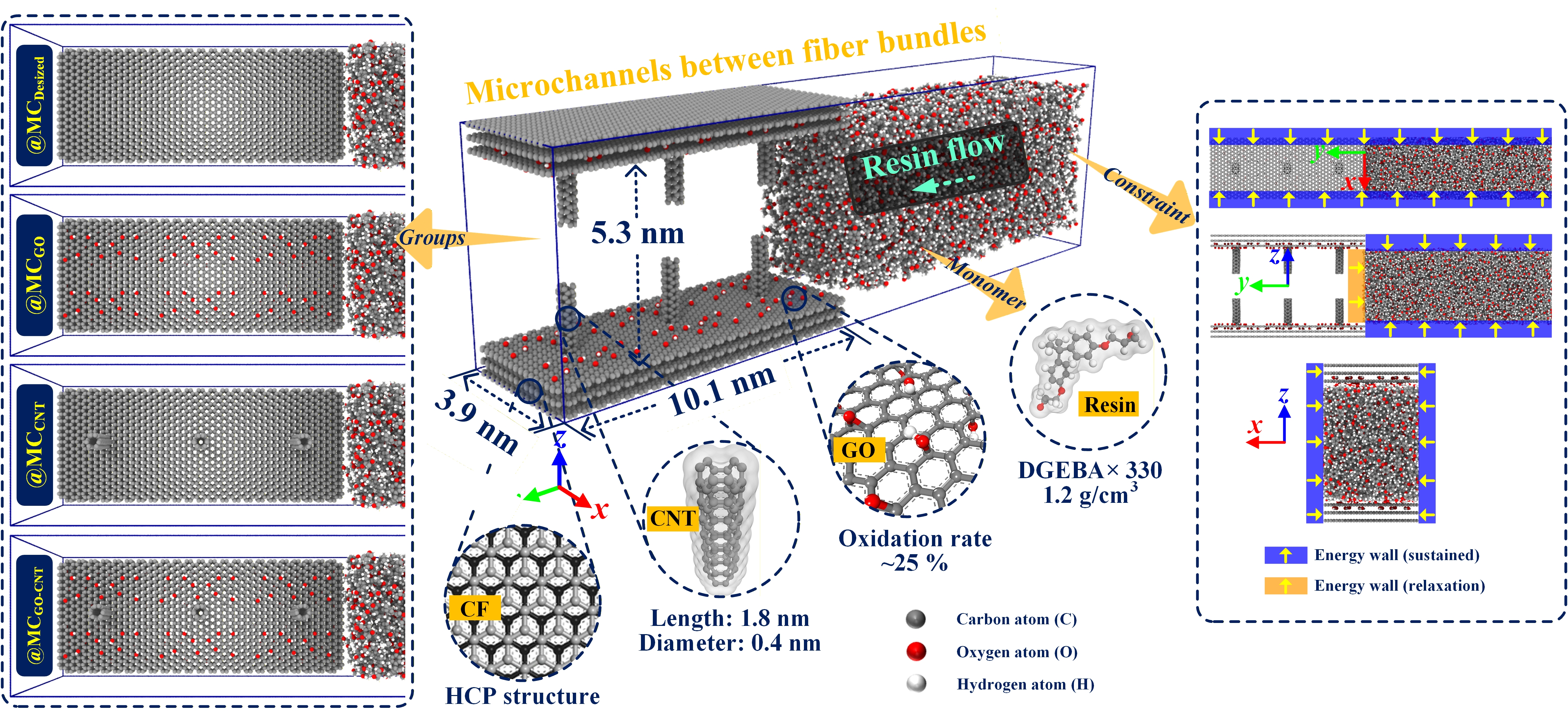
Figure 2. Schematic representation of all-atom models and corresponding boundary conditions, designed to simulate fluid flow in porous media representative of CF bundle interiors. CF: Carbon fiber; GO-CNT: graphene oxide-carbon nanotube; MC: microchannel; DGEBA: diglycidyl ether of bisphenol A; HCP: hexagonal closed-packed.
Force field
The consistent valence force field (CVFF) was employed to model both bonded and non-bonded interactions in the composite systems. The bonded terms included bond stretching, angle bending, and torsional potentials, while non-bonded interactions were described by the sum of Coulombic and van der Waals forces, represented by the Lennard-Jones 12-6 potential with a cutoff distance of 1.25 nm. Newton’s equations of motion were solved with the velocity-Verlet integration algorithm. All molecular dynamics simulations were conducted using the open-source large-scale atomic/molecular massively parallel simulator (LAMMPS), developed by Sandia National Laboratories, Livermore, CA, USA[35].
Calculation methods
Initial atomic velocities were assigned according to the Maxwell-Boltzmann distribution at 300 K. Before initiating infiltration, the DGEBA clusters were equilibrated under the NVT ensemble for 10 ps to relax local conformations while preserving structural tension. To prevent premature flow, a van der Waals energy barrier (1.25 nm in height) was applied at the channel entrance. After the barrier was removed, spontaneous capillary-driven resin infiltration was simulated for 30 ps with a time step of ∆t = 1 fs. No external forces were applied during this stage. Free boundary conditions were imposed in all directions, while energy walls were implemented to constrain the polymer within the simulation domain (as illustrated in Figure 2).
RESULTS AND DISCUSSION
Material characterizations
Figure 3 presents SEM images and XPS spectra of CF surfaces after different surface treatments. Compared with untreated fibers [Figure 3A1-A2], desized fibers exhibit a rougher surface with narrow, irregular grooves oriented along the fiber axis [Figure 3B1-B2]. These features indicate the effective removal of the sizing layer and exposure of the underlying turbostratic graphitic structure. This interpretation is further confirmed by the appearance of a π-π* transition signal associated with the graphitic domains. Following surface modification, distinct nanostructured morphologies are observed. GO deposited by EPD forms a continuous, bridge-like film across the CF surface [Figure 3C2], while CNTs form a forest-like array [Figure 3D2]. In the GO-CNT modified fibers, CNTs nucleate and grow on surface protrusions, producing a cauliflower-like morphology [Figure 3E1-E2]. This heterogeneous growth may be associated with localized heat flux during flame growth, which promotes irregular CNT growth at the protrusion sites.
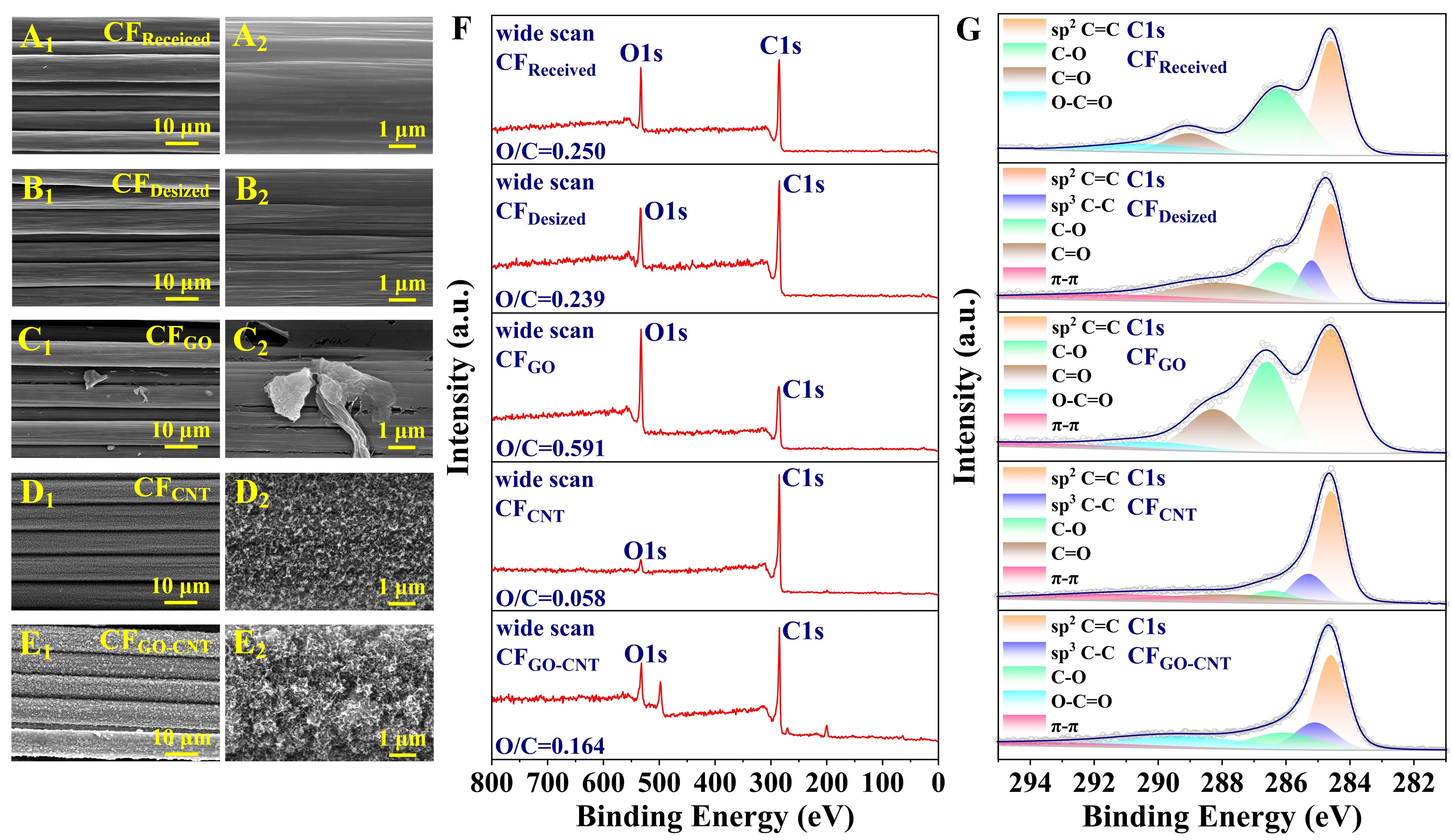
Figure 3. SEM images of CF surface morphologies after various treatments: (A1-A2) untreated CF (as received), (B1-B2) desized CF, (C1-C2) GO-modified CF, (D1-D2) CNT-modified CF, and (E1-E2) GO-CNT hybrid-modified CF. High-resolution XPS spectra of CF surfaces: (F) wide scan, and (G) deconvoluted C1s spectra. SEM: Scanning electron microscopy; CF: carbon fiber; GO-CNT: graphene oxide-carbon nanotube.
XPS analysis [Figure 3F and G] reveals that the modified fiber surfaces are composed predominantly of C and O. CNT modification reduces the surface O content, whereas GO deposition increases it [Table 2]. The high-resolution C1s spectra [Table 3] reveal strong π-π interaction (~292.1 eV) in samples modified with graphitic GO and CNTs, indicating the presence of aromatic domains. A prominent C-C peak (~285.2 eV) is observed in CFCNT and CFGO-CNT but is notably absent in CFGO, reflecting the C-C-rich CNT structure. In contrast, GO contributes more sp3-hybridized C and oxidized species, as evidenced by a strong C-O signal (~286.3 eV). Additionally, the enhanced O-C=O peak (~290.5 eV) in the CFGO-CNT sample suggests possible interfacial bonding between the edges of GO sheets and the tips of CNTs. The absence of a distinct C=O signal (~288.2 eV) may be attributed to ring-opening reactions of epoxy groups during flame treatment, which convert into more polar groups such as hydroxyls or carboxyl groups.
XPS surface elemental analysis of CF
| Sample | Atomic percentage (%) | Atomic ratio | |
| O | C | O/C | |
| CFReceived | 20.0 | 80.0 | 0.250 |
| CFDesized | 19.3 | 80.7 | 0.239 |
| CFGO | 37.2 | 62.8 | 0.592 |
| CFCNT | 5.5 | 94.5 | 0.058 |
| CFGO-CNT | 14.2 | 85.8 | 0.166 |
Proportion of carbon-related functional groups on CF surface
| Sample | Percentage content (%) | |||||
| C=C | C-C | C-O | C=O | O-C=O | π-π | |
| CFReceived | 38.78 | - | 39.74 | 11.01 | 10.47 | - |
| CFDesized | 31.14 | 12.36 | 20.35 | 22.44 | - | 13.71 |
| CFGO | 40.39 | - | 30.47 | 16.59 | 5.98 | 6.57 |
| CFCNT | 43.09 | 14.90 | 8.13 | 16.45 | - | 17.42 |
| CFGO-CNT | 37.30 | 15.08 | 15.61 | - | 20.66 | 11.36 |
Analysis of multi-scale flow behavior of resin in CFRP
Wettability of CF/epoxy interface
The static microscale wetting behavior of epoxy droplets on individual carbon fibers is shown in Figure 4. As shown in Figure 4A, epoxy resin droplets exhibit pronounced convex profiles on untreated fiber surfaces. In contrast, after modification with carbon nanomaterials, the droplet profile changes from convex to concave, forming a hydrodynamic curvature near the triple-phase contact line. This morphological transition indicates improved resin spreading over the modified fiber surface.
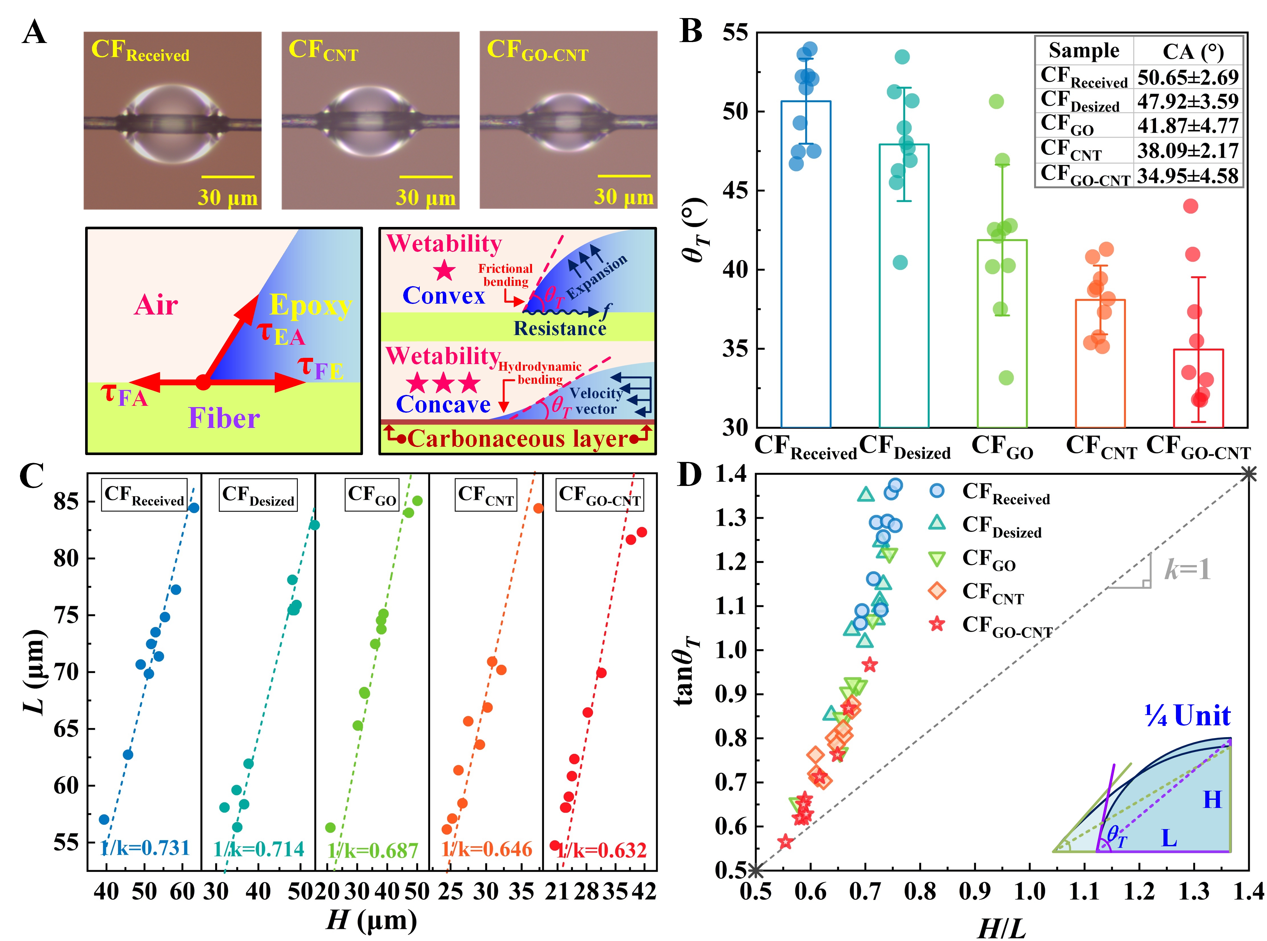
Figure 4. Wettability analysis of epoxy resin on CF monofilaments: (A) optical micrographs (OM) schematic representations of the droplet profiles and surface curvature; (B) static contact angles measured by the tangent method, with data presented as mean ± standard deviation (ten droplet profiles for each sample group); (C) droplets height versus length for contact-angle determination; (D) quantitative evaluation of wettability through functional correlation analysis. CF: Carbon fiber; GO-CNT: graphene oxide-carbon nanotube; CA: contact angle.
The contact angle of an individual fiber is typically evaluated using two main approaches: (a) direct measurement of the tangent angle at the three-phase contact line, and (b) geometric estimation based on the droplet height-to-length ratio. Direct measurements show that the static contact angle decreases from 50.65° to a minimum of 34.95° after surface modification [Figure 4B]. Consistent with this result, the droplet height-to-length ratio also decreases after surface modification [Figure 4C]. Based on these two measurements, a functional relationship was established between the tangent angle and the height-to-length ratio [Figure 4D]. A larger slope (> 1) with larger deviation from linearity indicates limited droplet spreading and relatively poor wettability, while a smaller slope suggests improved spreading behavior. Additionally, consistent slope values and closer proximity to the origin denote superior wetting performance. The tangent-angle measurements, geometric-ratio analysis, and functional fitting consistently indicate that the 3D nanostructures markedly improve the wettability of the CF/epoxy interface.
Table 4 presents the contact angles of individual CFs measured with two probe liquids and corresponding calculated surface free energies. Compared with CFReceived, CFGO-CNT exhibits markedly lower contact angles with both probe liquids. This trend is consistent with the static contact angle measurements and further supports the improvements in CF surface wettability induced by GO-CNT modification. Meanwhile, the total surface free energy of CFGO-CNT increases substantially, with a decrease in the dispersive component and a pronounced increase in the polar component. The polar component accounts for 88.6% of the total surface free energy. This shift is closely associated with changes in the surface chemistry and morphology of the fibers. On the untreated CF surface, the graphitic sp2 carbon structure provides dispersive interactions, while residual oxygen-containing groups contribute to polar interactions, resulting in a slightly higher polar component. Following GO-CNT modification, O-containing functional groups are introduced to the fiber surface, forming a rough 3D nanostructure. The increased surface polarity strengthens interactions between fiber and resin, while the nanoscale roughness increases the effective solid-liquid contact area. The synergistic effect of these chemical and morphological changes significantly increases both the polar component and total surface free energy of the fiber. This provides more favorable thermodynamic conditions for resin spreading, contributing to the transition of the droplet profile from convex to concave and facilitating resin spreading along the fiber surface.
Contact angles and surface free-energy components of different CFs
| Contact angles (°) | Surface energy (mN/m) | ||||
| Deionized water | Ethylene glycol | | | | |
| CFReceived | 74.7 ± 4.2 | 57.6 ± 6.4 | 29.8 ± 7.2 | 17.4 ± 3.8 | 12.4 ± 3.4 |
| CFGO-CNT | 59.5 ± 2.3 | 51.4 ± 2.1 | 43.8 ± 3.9 | 38.8 ± 3.1 | 5.0 ± 0.8 |
Capillary wicking dynamics in fiber bundles
In fiber bundles, resin transport begins with spontaneous capillary wicking through inter-fiber microchannels, as visualized by the fiber morphology in Figure 3D and E. This wicking process involves two distinct stages: an initial rapid phase (0-5 s) driven by capillary forces [Figure 5A], during which the resin rapidly penetrates along fiber surfaces and through inter-fiber gaps, followed by a slower, viscous-dominated phase where increasing resistance decelerates flow. Saturation is marked by an inflection point in the contact angle evolution (~5 s). Figure 5B and C illustrates the evolution of contact angle and the fitting results based on Equation (4) during the rapid infiltration stage. Using this method, kb was also obtained for different surface-modification conditions [Supplementary Figure 2]. The results show that kb is highly sensitive to the modification conditions, indicating that the carbon nanostructures influence capillary flow. Figure 5D compares the kb values obtained for different treatment groups. Optimized EPD and flame treatments increase kb by 31.7% and 67.3%, respectively. Notably, the GO-CNT hybrid exhibits the highest kb (0.186), exceeding the values obtained with either GO or CNT modification alone, and corresponding to a maximum increase of 84.2%. The significant increase in kb indicates that the GO-CNT nanostructure markedly enhances capillary-driven infiltration at the mesoscale. Here, “wicking” specifically refers to capillary-driven flow via microscale gaps between adjacent fibers, which is distinct from bulk resin infiltration at the fabric (macroscale) level.
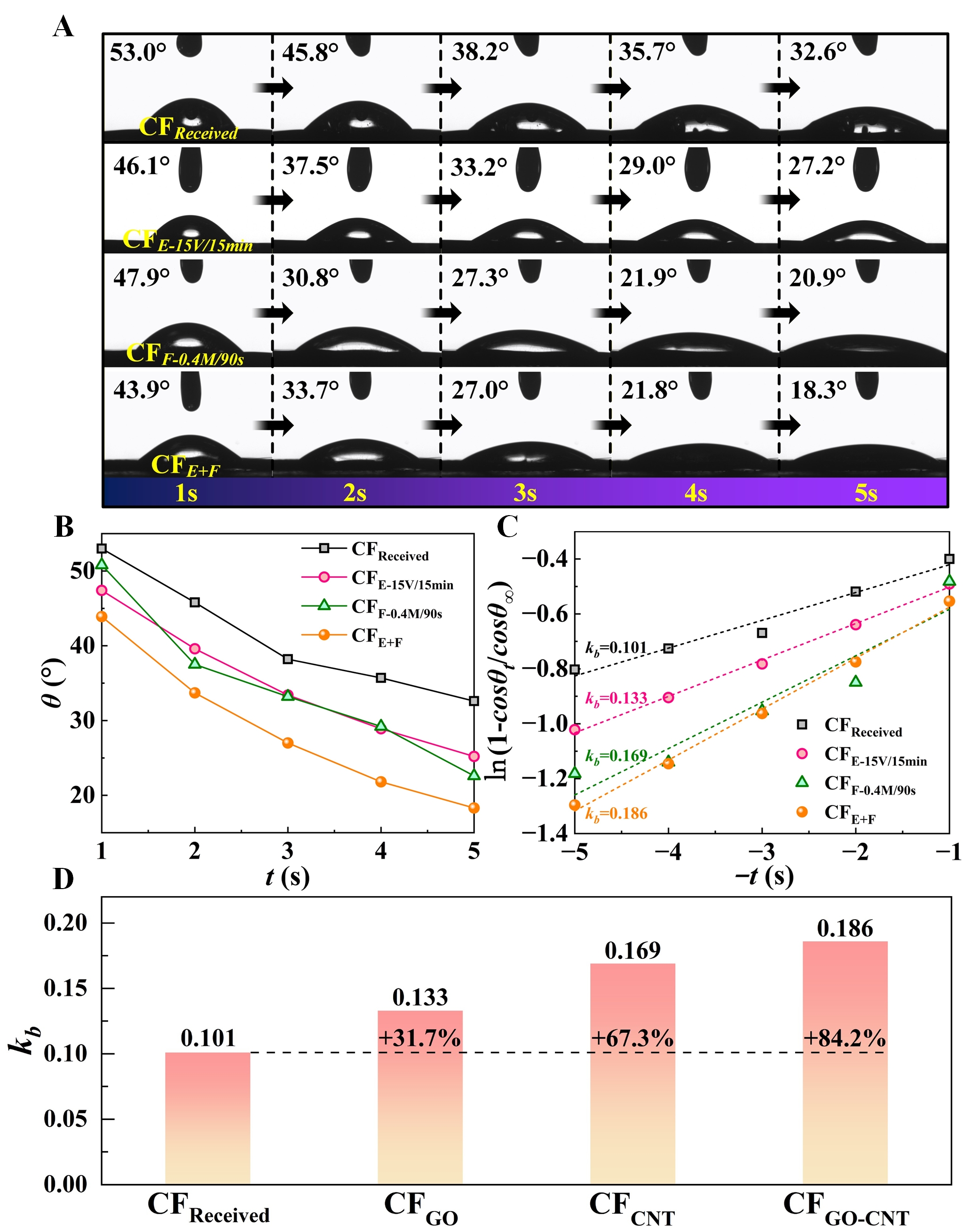
Figure 5. Resin infiltration kinetics in fiber bundles: (A) evolution of contact angle with time for different CF bundles; (B) infiltration curves of different CF bundles; (C) fitted curves used to determine kb values; and (D) comparison of kb among CF bundles subjected to different surface modifications. CF: Carbon fiber.
Flow assessment of CF woven fabric
The in-plane impregnation behavior of woven CF fabrics was evaluated using VARI. Under the applied vacuum pressure, the resin advanced from the inlet toward the outlet, forming a nonuniform flow front. The shape and velocity of the flow front are governed by factors including inter-bundle channel geometry, fiber wettability, resin viscosity, and capillary interactions at the fiber-resin interface. This macroscopic flow behavior can be described by Darcy flow.
Figure 6A presents the relationship between the squared flow-front position (
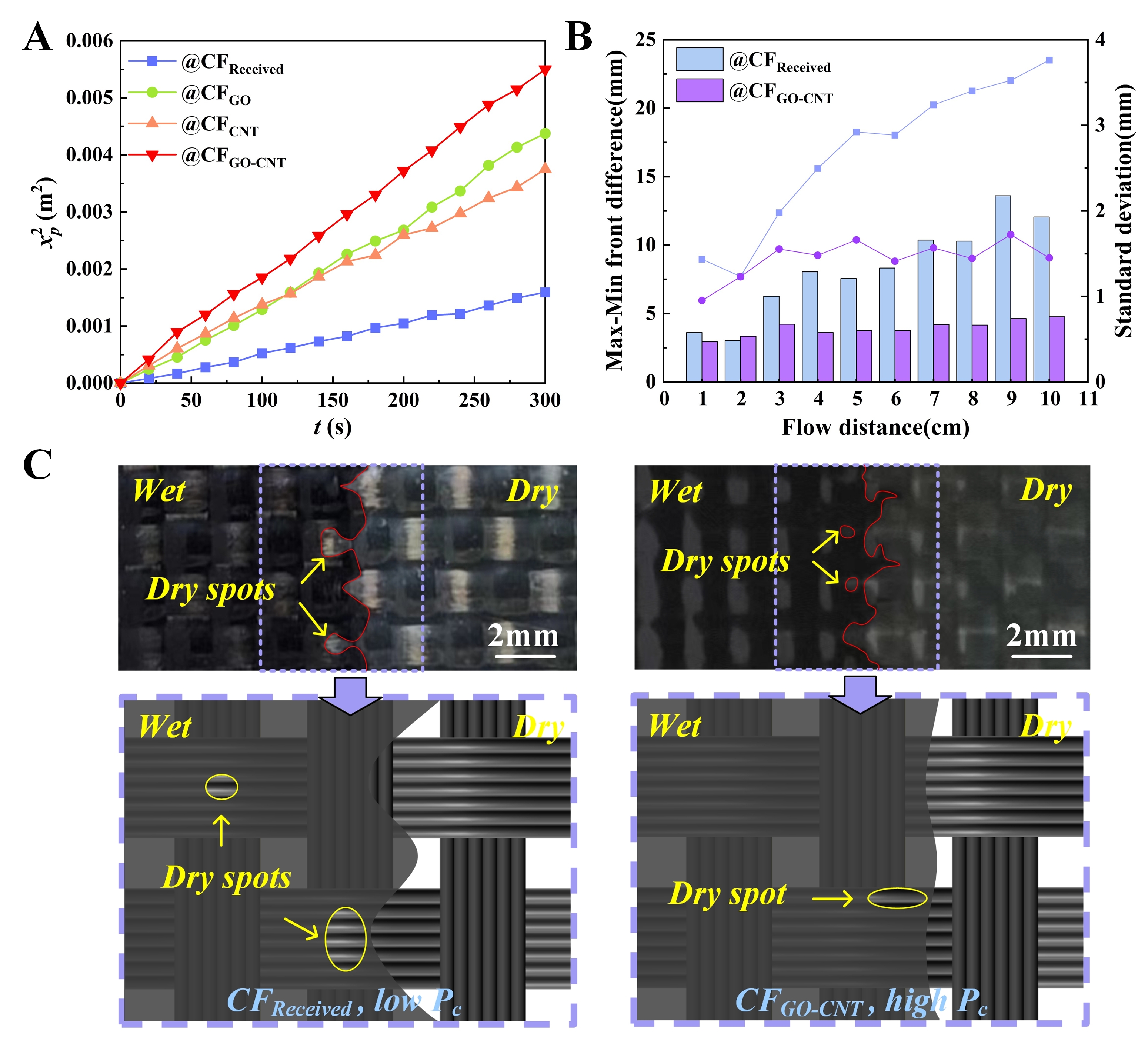
Figure 6. Macroscopic resin infiltration in T300 woven fabrics: (A) linearized infiltration kinetics (
To quantify the morphological evolution of the flow front, the flow-front range (the maximum lag behind the leading point) and the standard deviation were extracted [Figure 6B]. For the untreated fabric, the flow-front nonuniformity progressively increases as infiltration proceeds. In contrast, the flow front in the GO-CNT modified fabric remains relatively stable, with only a slight increase in spatial dispersion. This difference in macroscopic uniformity is associated with changes in the multiscale resin transport mechanisms. A clear dual-scale transport phenomenon is observed in the untreated fabric (left photos in Figure 6C): rapid Stokes flow through inter-bundle channels and slower capillary-driven flow within intra-bundle pores. This pronounced difference in flow velocity can cause void entrapment within the fiber bundles. In contrast, after GO-CNT modification (right photos in Figure 6C), the engineered nanostructured wetting layer substantially enhances intra-bundle infiltration. This enhancement reduces the velocity difference between intra-bundle and inter-bundle flows, resulting in a more continuous flow front and more uniform overall resin advancement. Moreover, the dry spots are smaller than those in the untreated fabric and are mainly confined to bundle boundaries, suggesting that they may be more readily filled as infiltration proceeds.
The reduction in final porosity [Supplementary Figure 3] further supports the role of GO-CNT nanostructures in balancing inter-bundle and intra-bundle flows, thereby promoting more coordinated resin transport across multiple scales. The increased surface polarity and roughness enhance the wetting driving force, which increases capillary pressure Pc and facilitates resin penetration into intra-bundle pores. These results indicate that the GO-CNT nanostructures enhance multiscale resin transport without compromising macroscopic flow. Overall, the improvements in interfacial wettability and bundle-scale wicking synergistically contribute to the enhanced resin filling efficiency observed at the fabric scale. Such multiscale regulation of resin transport may also extend beyond LCM to prepreg manufacturing, where improved impregnation could reduce initial air entrapment within the fiber tows, facilitate void removal during subsequent consolidation, and ultimately improve prepreg quality.
MD analysis of capillary flow induced by carbon nanostructure
Regulation mechanism of fiber/resin interface in porous media
Figure 7A shows the velocity distribution of the resin within the microchannels, revealing that the introduction of nanostructures significantly alters the velocity field. Generally, the flow velocity is higher at the channel center and follows the order MCGO-CNT > MCCNT > MCGO > MCCG. To further investigate the origin of these differences, the evolution of the imbibition depth over time was fitted. The penetration of epoxy (DGEBA) into the microchannels follows the scaling relationship: L(t) ~ t0.5 [Figure 7B], indicating a capillary-driven imbibition regime. The slope reflects the combined influence of capillary pressure and resin viscosity. The infiltration efficiency follows the order: MCGO-CNT ≈ MCCNT > MCGO > MCCG. The stronger effect of CNTs relative to GO may be associated with more extensive π-π stacking with the DGEBA aromatic rings, which enabled multi-dimensional adsorption. In contrast, the interaction with GO is governed primarily by shorter-range hydrogen bonding via its polar groups. It should be noted that the idealized MD models neglect morphological irregularities and local agglomeration in real nanostructures, which may lead to quantitative deviations in the predicted velocity profiles and imbibition depth. Nevertheless, the simulations preserve the intrinsic differences in interfacial interactions among the systems, and the resulting performance rankings remain consistent with the qualitative experimental trends.
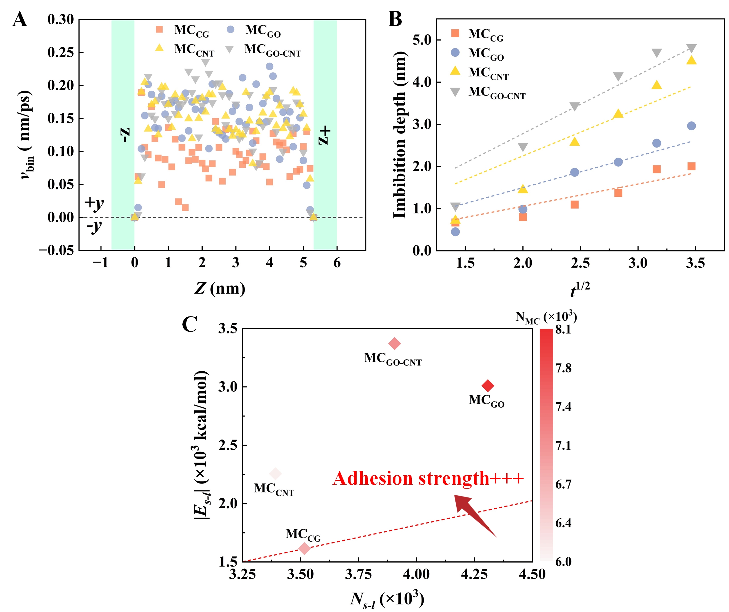
Figure 7. MD simulations of epoxy resin flow behavior in microchannels: (A) velocity distribution profiles of the polymer across different microchannels; (B) penetration depth as a function of time; and (C) solid-liquid interaction energy (Es-l) versus number of resin atoms infiltrating the microchannel. MD: Molecular dynamics; GO-CNT: graphene oxide-carbon nanotube.
As infiltration progressed, the solid-liquid interfacial interaction energy (Es-l) increased and eventually plateaued at equilibrium [Figure 7C]. In the absence of covalent bonding, Es-l is dominated by nonbonded interactions (van der Waals forces and charge transfer), as expressed by:
where Esystem, Eepoxy, and Esubstrate denote the total energy of the full system, the resin, and the fiber substrate, respectively. It should be noted that a positive Es-l indicates repulsive atomic interactions, whereas a negative value signifies attractive forces. In all MD simulations, Es-l values were negative, confirming inherently attractive resin-substrate interactions.
The interfacial energy Es-l is influenced by channel morphology, the number of resin molecules entering the channel, and their adsorption near channel walls [Figure 7C]. Compared with MCGO, MCCNT exhibits lower |Es-l|, indicating weaker interfacial retention. Nevertheless, the CNT architecture enhances the attraction of fluid molecules, consistent with the higher permeation rate observed in MCCNT [Figure 7B]. However, even in the idealized MD models, the 3D CNT network increases pathway tortuosity and creates local constrictions, thereby introducing steric hindrance. In real hierarchical coatings, random CNT entanglement and nonuniform surface coverage may further increase this steric hindrance. As infiltration proceeds, DGEBA molecules can accumulate around the CNTs, resulting in local molecular crowding that restricts molecular mobility and limits further penetration. In contrast, MCGO displays higher |Es-l| because its polar functional groups promote epoxy-chain adsorption and molecular retention near channel walls. However, without the transport-promoting effect of the CNT architecture, its overall penetration rate remains lower than that of MCGO-CNT. Over time, the lamellar GO surface facilitates the redistribution of DGEBA molecules along the channel walls, enabling continued resin penetration into the confined channel.
Capillary pressure of resin in porous media
In the MD infiltration simulations, epoxy penetration is driven by a pressure difference, ∆P, which comprises the applied external pressure, Papp, and the intrinsic capillary pressure, Pc. Assuming 2D flow and neglecting gravitational effects, the governing relationship can be expressed as follows[36,37]:
Here, Pc at the unsaturated flow front can be interpreted as the ratio of the intercept to the slope in the functional relationship between the independent variable Papp and
Based on this derivation, Pc in MCCG and MCGO-CNT systems are presented in Figure 8A. To construct the
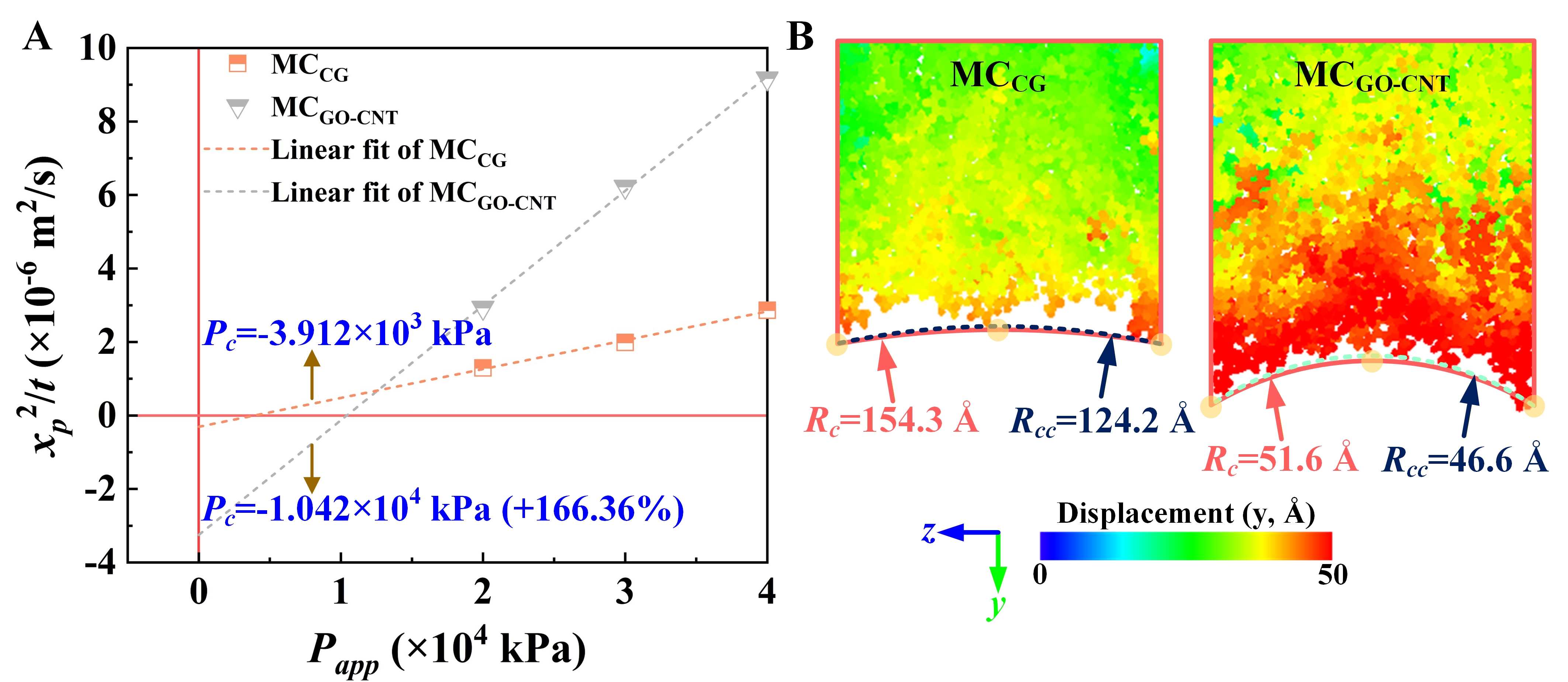
Figure 8. (A) Plots of (
where
CONCLUSIONS
This study systematically investigates how GO-CNT hybrid nanostructures regulate resin transport across multiple scales in CF/epoxy systems, thereby improving their processability during LCM.
The synergistic combination of GO-derived surface polarity and CNT-induced nanoscale roughness increased the polar component of the total CF surface free energy. Consequently, the contact angle decreased from 50.65° to 34.95°, indicating a substantial improvement in fiber-resin wettability. The resulting 3D nanostructured interface further enhanced capillary-driven wicking, evidenced by an 84.2% increase in the infiltration rate constant (kb). This enhanced mesoscale infiltration led to more uniform flow-front advancement and improved overall in-plane impregnation of the fabric, with the average velocity increasing by 85.7%.
MD simulations facilitated molecular-level insight into the interfacial mechanisms that underlay these macroscopic enhancements: GO primarily increased the solid-liquid interfacial interactions through surface polarity, whereas CNTs promoted a more concentrated interfacial-energy distribution. Their combined effects produced a highly favorable local velocity field and increased the magnitude of the capillary pressure by 166.4%. These molecular-scale findings have provided a mechanistic explanation for the experimental increase in bundle wicking (increased kb) and the enhanced resin-filling rate observed at the fabric scale.
Notably, the flame-synthesis step enables rapid CNT growth (< 2 min), while the electrophoretic-flame synthesis method shows potential for industrial scalability. Future studies should evaluate the performance of the modified fibers under high-pressure and high-speed resin filling conditions used in industrial resin transfer moulding (RTM) and high pressure RTM processes to further assess their practical applicability.
DECLARATIONS
Authors’ contributions
Data curation, formal analysis, writing-reviewing: Zhang, Y.; Zhang, M.
Methodology, software, writing-original draft: Zhang, M.
Investigations: Zhang, M.; Zhou, R.
Conceptualization: Zhou, H. (Zhou Helezi)
Writing-reviewing and editing: Zhou, H. (Zhou Helezi); Mai, Y. W.
Resources: Zhou, H. (Zhou Huamin); Mai, Y. W.
Supervision, funding acquisition: Zhou, H. (Zhou Helezi)
Availability of data and materials
The data supporting the findings of this study are available within this Article and Supplementary Materials. Further data are available from the corresponding authors upon request.
AI and AI-assisted tools statement
During the preparation of this manuscript, the AI tool Grammarly (version 1.2.272.1911, released 2026-06-24) was used solely for language editing. The tool did not influence the study design, data collection, analysis, interpretation, or the scientific content of the work. All authors take full responsibility for the accuracy, integrity, and final content of the manuscript.
Financial support and sponsorship
The authors would like to acknowledge the financial support from the National Natural Science Foundation of China (No. 52275336) and Defense Industrial Technology Development Program (No. JCKY2024206A005).
Conflicts of interest
All authors declared that there are no conflicts of interest.
Ethical approval and consent to participate
Not applicable.
Consent for publication
Not applicable.
Copyright
© The Author(s) 2026.
Supplementary Materials
REFERENCES
1. Zhao, H.; Chen, L.; Yun, J.; et al. Improved thermal stabilities, ablation and mechanical properties for carbon fibers/phenolic resins laminated composites modified by silicon-containing polyborazine. Eng. Sci. 2018, 2, 57-66. https://www.espublisher.com/journals/articledetails/168/ (accessed 2026-08-26).
2. Saba, N.; Tahir, P.; Jawaid, M. A review on potentiality of nano filler/natural fiber filled polymer hybrid composites. Polymers 2014, 6, 2247-73.
3. Sahu, R.; Ponnusami, S. A.; Weimer, C.; Harursampath, D. Interface engineering of carbon fiber composites using CNT: a review. Polym. Compos. 2024, 45, 9-42.
4. Shi, W.; Guo, R.; Tian, G.; et al. A broadband self-powered and stable photothermoelectric detector based on Ag2Se/MWCNTs composite fabricated via screen printing. Microstructures 2025, 5, 2025081.
5. Wu, D.; Yao, Z.; Sun, X.; et al. Mussel-tailored carbon fiber/carbon nanotubes interface for elevated interfacial properties of carbon fiber/epoxy composites. Chem. Eng. J. 2022, 429, 132449.
6. Yao, Z.; Zhang, K.; Xia, A.; et al. One-step in-situ growth of CNTs on oxidized carbon fiber: effects of catalyst concentration and growth time on mechanical properties of carbon fiber. Polym. Compos. 2024, 45, 5827-38.
7. Feng, Y.; Liu, S.; Zhang, S.; et al. Construction of dendritic polymers on carbon fiber surfaces to improve the interfacial bonding of carbon fiber/silicone rubber composites. Colloids. Surf. A. Physicochem. Eng. Asp. 2023, 676, 132108.
8. Quan, G.; Wu, Y.; Li, W.; et al. Construction of cellulose nanofiber/carbon nanotube synergistic network on carbon fiber surface to enhance mechanical properties and thermal conductivity of composites. Compos. Sci. Technol. 2024, 248, 110454.
9. Parasuram, S.; Banerjee, P.; Raj, R.; Kumar, S.; Bose, S. Electrophoretically deposited multiscale graphene oxide/carbon nanotube construct mediated interfacial engineering in carbon fiber epoxy composites. ACS. Appl. Mater. Interfaces. 2023, 15, 28581-93.
10. De, B.; Bera, M.; Bhattacharjee, D.; Ray, B. C.; Mukherjee, S. A comprehensive review on fiber-reinforced polymer composites: raw materials to applications, recycling, and waste management. Prog. Mater. Sci. 2024, 146, 101326.
11. Zhou, H.; Zhang, M.; Gong, L.; Li, L.; Zhou, H.; Mai, Y. W. Three-dimensional nano-structural design for enhanced damping performance of carbon fiber reinforced polymer composites with balanced mechanical performance. Compos. Part. B. Eng. 2025, 298, 112351.
12. Bodaghi, M.; Costa, R.; Gomes, R.; Silva, J.; Correia, N.; Silva, F. Experimental comparative study of the variants of high-temperature vacuum-assisted resin transfer moulding. Compos. Part. A. Appl. Sci. Manuf. 2020, 129, 105708.
13. Szarski, M.; Chauhan, S. Instant flow distribution network optimization in liquid composite molding using deep reinforcement learning. J. Intell. Manuf. 2023, 34, 197-218.
14. Yoshihara, K.; Kamei, Y.; Mizuno, A.; Ohgaki, H.; Hori, T.; Ueno, I. Effect of wettability on viscous fluid impregnation in single-layer woven-fibre bundles driven by pressure difference. Compos. Part. A. Appl. Sci. Manuf. 2020, 138, 106049.
15. Yun, M.; Carella, T.; Simacek, P.; Advani, S. Stochastic modeling of through the thickness permeability variation in a fabric and its effect on void formation during vacuum assisted resin transfer molding. Compos. Sci. Technol. 2017, 149, 100-7.
16. Neunkirchen, S.; Bender, M.; Schledjewski, R. Effect of binder activation on in-plane capillary flow in multilayer stacks of carbon fiber fabrics. Appl. Compos. Mater. 2024, 31, 709-19.
17. Endruweit, A.; Zeng, X.; Matveev, M.; Long, A. Effect of yarn cross-sectional shape on resin flow through inter-yarn gaps in textile reinforcements. Compos. Part. A. Appl. Sci. Manuf. 2018, 104, 139-50.
18. Syerko, E.; Binetruy, C.; Comas-cardona, S.; Leygue, A. A numerical approach to design dual-scale porosity composite reinforcements with enhanced permeability. Mater. Des. 2017, 131, 307-22.
19. Ma, L.; Zhu, Y.; Feng, P.; et al. Reinforcing carbon fiber epoxy composites with triazine derivatives functionalized graphene oxide modified sizing agent. Compos. Part. B. Eng. 2019, 176, 107078.
20. Lyu, H.; Jiang, N.; Hu, J.; Li, Y.; Zhou, N.; Zhang, D. Preparing water-based phosphorylated PEEK sizing agent for CF/PEEK interface enhancement. Compos. Sci. Technol. 2022, 217, 109096.
21. Zhang, M.; Liu, B.; Luan, Y.; et al. Nano-level insights on the interfacial wettability of graphene oxide-coated carbon fiber/epoxy composite. J. Mater. Sci. 2023, 58, 8815-32.
22. Deng, C.; Jiang, J.; Liu, F.; et al. Effects of electrophoretically deposited graphene oxide coatings on interfacial properties of carbon fiber composite. J. Mater. Sci. 2015, 50, 5886-92.
23. Du, X.; Xu, F.; Liu, H.; Miao, Y.; Guo, W.; Mai, Y. Improving the electrical conductivity and interface properties of carbon fiber/epoxy composites by low temperature flame growth of carbon nanotubes. RSC. Adv. 2016, 6, 48896-904.
24. Feng, S.; Zhu, P.; Zheng, H.; et al. Three-dimensional capillary ratchet-induced liquid directional steering. Science 2021, 373, 1344-8.
25. Falk, K.; Sedlmeier, F.; Joly, L.; Netz, R. R.; Bocquet, L. Molecular origin of fast water transport in carbon nanotube membranes: superlubricity versus curvature dependent friction. Nano. Lett. 2010, 10, 4067-73.
26. Kim, J.; Kwon, D.; Shin, P.; et al. Interfacial properties and permeability of three patterned glass fiber/epoxy composites by VARTM. Compos. Part. B. Eng. 2018, 148, 61-7.
27. Xiao, Y.; Xu, J.; Wang, M.; Wang, B.; Yuan, S.; Yang, C. Multiscale model of the RTM process: from mesoscale anisotropic permeability of woven structures to macroscale resin impregnation. Ind. Eng. Chem. Res. 2021, 60, 8269-79.
28. Yu, J.; Zheng, Q.; Hou, D.; et al. Insights on the capillary transport mechanism in the sustainable cement hydrate impregnated with graphene oxide and epoxy composite. Compos. Part. B. Eng. 2019, 173, 106907.
29. Whitaker, S. Flow in porous media I: a theoretical derivation of Darcy’s law. Transp. Porous. Med. 1986, 1, 3-25.
30. Ali, M. A.; Umer, R.; Khan, K. A.; Samad, Y. A.; Liao, K.; Cantwell, W. Graphene coated piezo-resistive fabrics for liquid composite molding process monitoring. Compos. Sci. Technol. 2017, 148, 106-14.
31. Lomov, S. V.; Beyers, L.; Gorbatikh, L.; et al. Permeability and compressibility of CNT/CNF-grafted reinforcements. In 10th International Conference on Flow Processes in Composite Materials (FPCM-10), Ascona, Switzerland, July 11-15, 2010; p 1-5. https://www.researchgate.net/profile/Vitaly-Koissin/publication/254860154_Permeability_and_compressibility_of_CNTCNF_grafted_reinforcements/links/5f7dd1da92851c14bcb4d955/Permeability-and-compressibility-of-CNT-CNF-grafted-reinforcements.pdf (accessed 2026-08-26).
32. Garat, W.; Pucci, M. F.; Leger, R.; et al. Surface energy determination of fibres for liquid composite moulding processes: method to estimate equilibrium contact angles from static and quasi-static data. Colloids. Surf. A. Physicochem. Eng. Asp. 2021, 611, 125787.
33. Ravel, R.; Pucci, M. F.; Liotier, P. Influence of the surface energy of a basalt fiber on capillary wicking and in-plane permeability of reinforcements. Compos. Part. A. Appl. Sci. Manuf. 2024, 187, 108496.
34. Song, Y.; Liu, C.; Li, H.; et al. Optimizing dual-scale wettability of epoxy resin on large-tow carbon fiber via tension-driven capillary wicking. Compos. Part. B. Eng. 2023, 264, 110936.
35. Plimpton, S. Fast parallel algorithms for short-range molecular dynamics. J. Comput. Phys. 1995, 117, 1-19.
36. Li, M.; Wang, S.; Gu, Y.; Zhang, Z.; Li, Y.; Potter, K. Dynamic capillary impact on longitudinal micro-flow in vacuum assisted impregnation and the unsaturated permeability of inner fiber tows. Compos. Sci. Technol. 2010, 70, 1628-36.
Cite This Article
 Open Access
How to Cite
Download Citation
If you have the appropriate software installed, you can download article citation data to the citation manager of your choice. Simply select your manager software from the list below and click on download.
Export Citation File
Type of Import
Tips on Downloading Citation
Citation Manager File Format
Type of Import
Direct Import: When the Direct Import option is selected (the default state), a dialogue box will give you the option to Save or Open the downloaded citation data. Choosing Open will either launch your citation manager or give you a choice of applications with which to use the metadata. The Save option saves the file locally for later use.
Indirect Import: When the Indirect Import option is selected, the metadata is displayed and may be copied and pasted as needed.
About This Article
Copyright

Data & Comments
Data
0











Comments
Comments must be written in English. Spam, offensive content, impersonation, and private information will not be permitted. If any comment is reported and identified as inappropriate content by OAE staff, the comment will be removed without notice. If you have any queries or need any help, please contact us at [email protected].