


Development of nano-sized LiFePO4 dry cathodes with enhanced flexibility and mechanical robustness for roll-to-roll dry coating process
 0
0 
Abstract
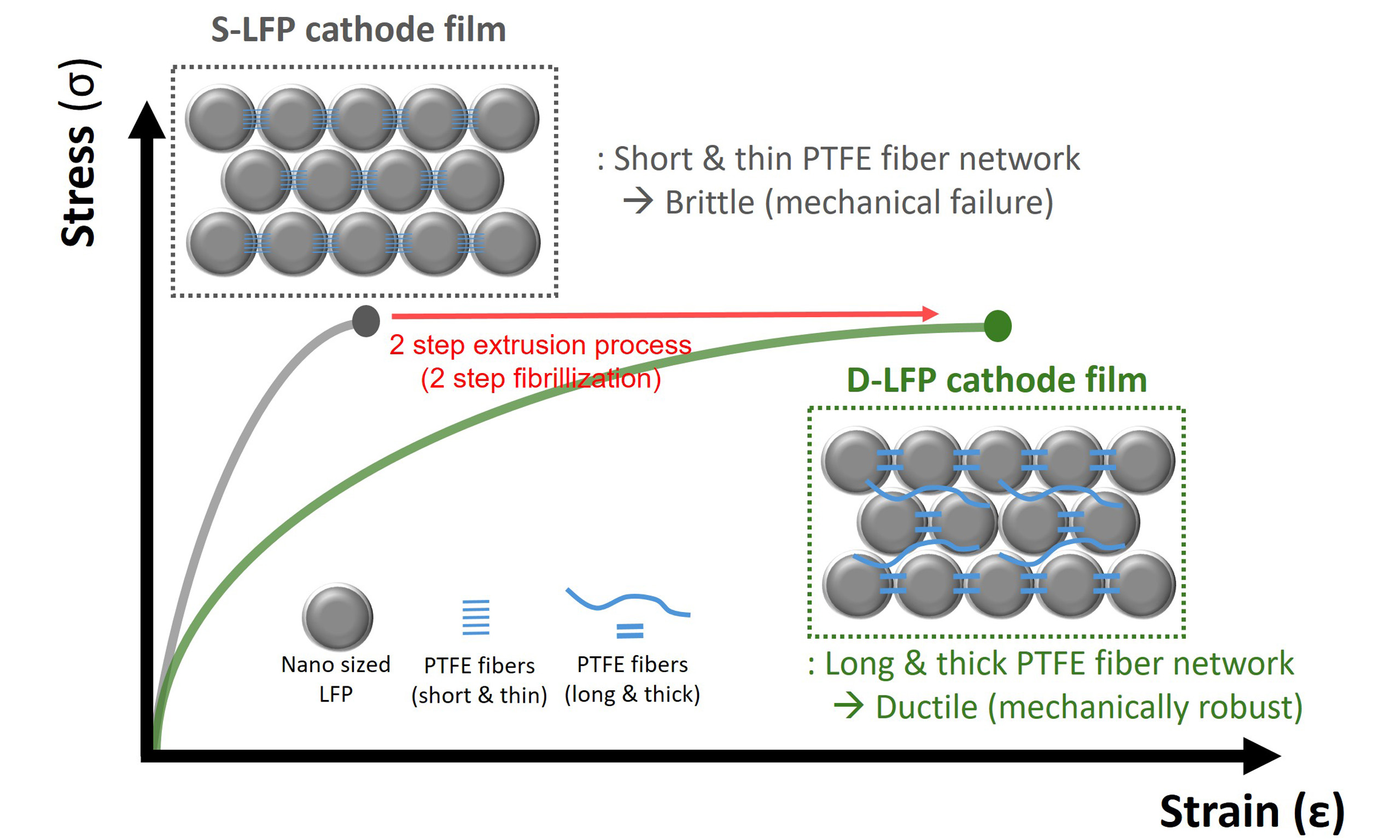
The polytetrafluoroethylene (PTFE) binder-based roll-to-roll dry coating process has emerged as a promising alternative to conventional slurry-based methods for fabricating thick electrodes in high-energy-density lithium-ion batteries (LIBs). However, applying nano-sized lithium iron phosphate (LiFePO4, LFP) to this process remains challenging, as the high specific surface area of nano-sized LFP leads to the formation of short and thin PTFE fiber network that cannot ensure the mechanical integrity of dry cathode at low PTFE binder content. Consequently, the nano-sized LFP dry cathode suffers from poor flexibility and mechanical brittleness, limiting its applicability in
Keywords
INTRODUCTION
The rapid growth of the electric vehicle (EV) market has accelerated the demand for high-energy-density lithium-ion batteries (LIBs) that are both safe and cost-competitive[1,2]. While high nickel layered oxide cathodes [e.g., lithium nickel cobalt manganese oxide (NCM), lithium nickel cobalt aluminum oxide (NCA)] have been widely adopted due to their higher capacity over 200 mAh g-1, they face issues such as unstable raw material prices, poor thermal safety, and growing concerns about both safety and production cost[3,4]. In this context, lithium iron phosphate (LiFePO4, LFP) cathodes are attracting significant attention for applications where safety, lifespan, and cost-effectiveness are critical-such as in mid-range EVs and stationary energy storage systems (ESS)[5]. LFP offers notable advantages including high thermal and chemical stability, long cycle life, and low cost[6-9]. However, its relatively low theoretical capacity
However, the fabrication of thick electrodes is difficult using conventional slurry-based (wet coating) methods. The wet coating processes suffer from issues such as binder migration during solvent evaporation, leading to inhomogeneous pore distribution and reduced adhesion between electrode and current collectors, thereby leading to the deterioration in electrochemical performance-particularly when electrode thickness increases[14]. Accordingly, the polytetrafluoroethylene (PTFE)-based roll-to-roll dry coating processes have emerged as a promising alternative to overcome the limitations of wet coating processes[15-18]. In the roll-to-roll dry coating process, active materials, conductive additives, and polymeric binders are mechanically dry-mixed under high shear forces to form dry mixtures. These dry mixtures are then calendered and laminated to form free-standing electrode film and dry electrode without requiring any solvent, drying, or solvent recovery steps [Supplementary Figure 1]. A critical advantage of the dry coating process lies in the fibrillization behavior of PTFE binders, which forms fibrous networks under mechanical shear stress[19-22]. These PTFE fiber networks improve the adhesion among active material particles, thereby enhancing the mechanical integrity and structural stability of the electrode. As a result, research on LFP dry electrodes using dry coating processes has gained considerable attention in recent years[23,24].
However, the application of dry coating processes to LFP still presents several technical challenges. Given the low Li-ion and electronic conductivity of LFP, the nano-sized particles with their high specific surface area (SSA) are essential to improve Li-ion and electron transport pathways within the electrode[25-27]. Yet, the high SSA of nano-sized LFP requires a higher binder content to ensure sufficient mechanical cohesion between LFP particles. In contrast, higher binder content lowers the proportion of LFP particles, lowering the overall energy density and thereby reducing the effectiveness of thick electrode designs. Even more critically, nano-sized LFP dry cathodes with low PTFE binder content exhibit significant brittleness, making them susceptible to cracking and fracture. Unlike micro-sized NCA dry cathode and graphite dry anode films, nano-sized LFP dry cathode films showed poor mechanical properties with poor ductility and a high tendency for fracture of cathode film after bending, which severely limits their suitability for roll-to-roll processing [Supplementary Figures 2-4]. To address this issue, various conductive agents were tested to identify the most suitable one for the fabrication of nano-sized LFP dry cathodes. Moreover, the fibrillization behavior of PTFE has been controlled by adjusting the screw configuration inside the extrusion equipment to develop the nano-sized LFP dry cathodes[28,29]. However, the underlying mechanism of this brittleness, as well as its correlation with characteristics of LFPs and PTFE fibrillization behavior, has yet to be fully elucidated. Accordingly, the application of the dry coating process to nano-sized LFP for thick cathode remains highly challenging.
In this study, we investigated the fibrillization behavior of PTFE depending on the particle size of
MATERIALS AND METHODS
Fabrication of LFP dry cathode film and dry cathode
LFP dry cathode films and dry cathodes were fabricated via a roll-to-roll dry coating process using LiFePO4, PTFE binder, and either carbon black (CB) or carbon nanotube (CNT) as the conductive agents, supplied by Samsung SDI. The dry powder mixture was homogenized using a dry mixer (L8-2k, KMTECH, Korea). All dry mixing processes in this work were conducted at 6,000 RPM for 1 h. For the two-step extrusion process, the 1st stage was performed under the same conditions (6,000 RPM for 1 h), while the 2nd stage was conducted at 10,000 RPM for 3 min. The total amount of the composite (LFP/CNT/PTFE) used in each batch was 500 g. Then, the dry mixed powder was extruded using a twin-screw extruder (HCK 25-24/CPC, HANKOOK E.M, Korea), crushed into granules (L8-2k, KMTECH, Korea), and rolled into films using a roller (KRM-80, KMTECH, Korea). The final LFP dry cathode films were laminated onto carbon-coated aluminum (Al) current collectors using a roll press (mp200, Rohtech, Korea).
Materials characterization
The morphology and microstructure of the electrodes were observed using field-emission scanning electron microscopy (FE-SEM, JSM-7600F, JEOL, Japan). Particle size distribution of the LFP powders was measured using a laser diffraction analyzer (Mastersizer 3000, Malvern Instruments, UK), and their SSA was determined by Brunauer-Emmett-Teller (BET) analysis (3Flex, Micromeritics Instrument Corporation, UK). Thermal behavior and crystallinity of PTFE in the composites were analyzed by differential scanning calorimetry (DSC, Q20, TA Instruments, USA) under a nitrogen atmosphere. The surface properties of the carbon coating layer on LFP particles were investigated using Raman spectroscopy (LabRAM HR Evolution, HORIBA, Japan). Mechanical properties of the dry LFP cathode films were evaluated using a universal testing machine (UTM, AGS-J, Shimadzu, Japan) under a constant strain rate and a micro-indentation test using a Vickers indenter (STeP500 MCT3, Anton Paar) under a fixed load of 3 N. Bending test was performed by bending the dry LFP cathode film around a stainless steel rod to evaluate its flexibility. Electronic conductivity (sheet resistance) was measured using a four-point probe system (MCP-T610, Mitsubishi, Japan).
Electrochemical evaluation
Electrochemical performance of the dry LFP cathodes was evaluated using 2032-type coin half cells assembled with Li metal (200 μm) as the counter electrode, a polypropylene (PP) separator (20 μm, Celgard 2400), and an electrolyte consisting of 1.15 M LiPF6 in EC/EMC/DMC (3:5:2 by volume) with 5 wt% fluoroethylene carbonate (FEC, PANAX StarLyte, Korea). The active material loading of the cathodes was
RESULTS AND DISCUSSIONS
PTFE fibrillization behavior depending on the particle size of LFP
Two types of LFP - small-sized LFP (S-LFP, nano-sized LFP) and large-sized LFP (L-LFP) - were applied to the roll-to-roll dry coating process to investigate the effect of LFP particle size on PTFE fibrillization behavior. Particle size distribution analysis revealed that the S-LFP sample exhibits an average size near 700~800 nm, whereas L-LFP shows a broader distribution centered around 10 μm, as further confirmed by SEM images [Figure 1A and Supplementary Figure 5]. The BET measurement showed that S-LFP
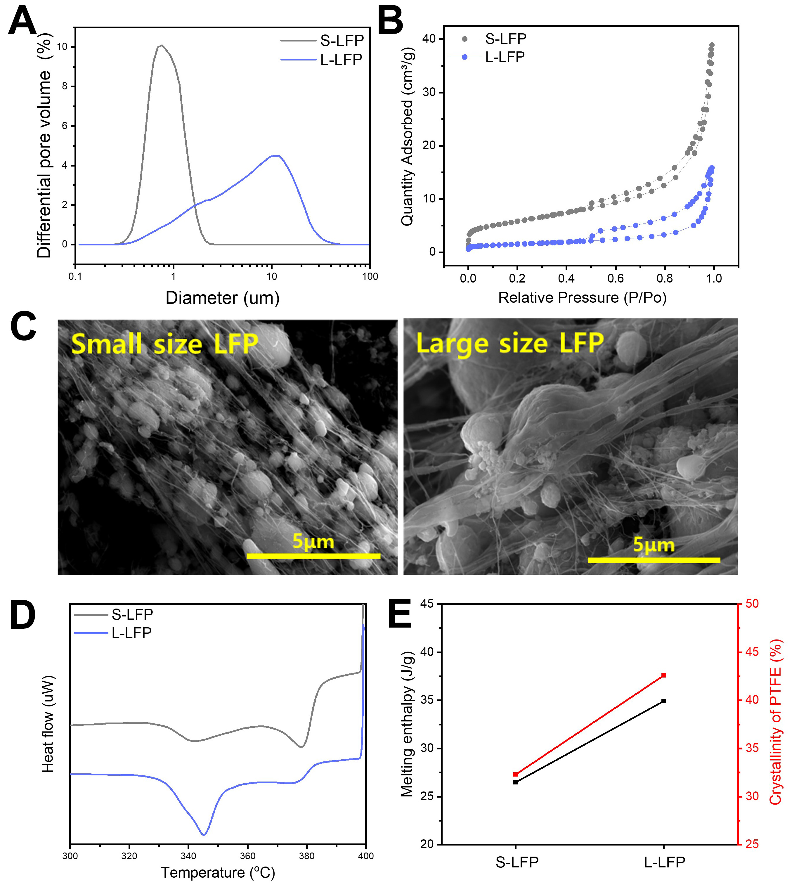
Figure 1. PTFE fibrillization behavior depending on the particle size of LFP. (A) Particle size distribution and (B) specific surface area of S-LFP and L-LFP; (C) SEM images of LFP/PTFE (7/3) granules after the extrusion process; (D) DSC measurement of LFP/PTFE (7/3) composite and (E) melting enthalpy and crystallinity of PTFE within LFP/PTFE (7/3) granules. PTFE: Polytetrafluoroethylene; LFP: LiFePO4; S-LFP: small-sized LFP; L-LFP: large-sized LFP; SEM: scanning electron microscopy; DSC: differential scanning calorimetry.
Additionally, to examine whether the surface characteristics of the carbon layer coated on LFP could affect interfacial friction between LFP and PTFE and, thus, PTFE fibrillization behavior, Raman spectroscopy was conducted [Supplementary Figure 6]. The Raman spectra of S-LFP and L-LFP showed no significant differences in D/G ratio or peak width, suggesting that the carbon layer coated on LFP does not significantly affect the PTFE fibrillization behavior within the LFP/PTFE granule[34]. These results highlighted the critical role of LFP particle size in determining PTFE fibrillization behavior. Specifically, a higher SSA resulting from the smaller particle size of S-LFP increases the interfacial contact with PTFE, which induces the enhanced shear-induced deformation of PTFE and leads to excessive PTFE fibrillization, ultimately forming a thin PTFE fiber network within the LFP/PTFE granule.
Mechanical properties and microstructure of LFP dry cathodes
Then, to investigate how PTFE fibrillization behavior affects the mechanical properties of LFP dry cathode films in practical composition, LFP dry cathode films, with a composition ratio of LFP/CB/PTFE = 94:3:3, were fabricated via roll-to-roll dry coating process. As shown in the digital images, the L-LFP dry cathode film successfully formed a continuous and flexible free-standing film. In contrast, the S-LFP dry cathode film appeared highly brittle, with severe edge cracking during the calendering process [Supplementary Figure 7]. To identify the origin of these differences, top- and cross-sectional view SEM analysis was conducted. The morphology of PTFE fibers observed in the LFP dry cathode films closely mirrored the PTFE fibrillization behavior previously seen in the LFP/PTFE (7/3) granules. In the S-LFP dry cathode film, a dense PTFE fiber network was found between the nano-sized particles; however, these PTFE fibers were thin and short, as clearly seen in the top-view images [Figure 2A and B]. In contrast, the L-LFP dry cathode film exhibited a thick and long PTFE fiber network, interconnecting the micro-sized LFP particles
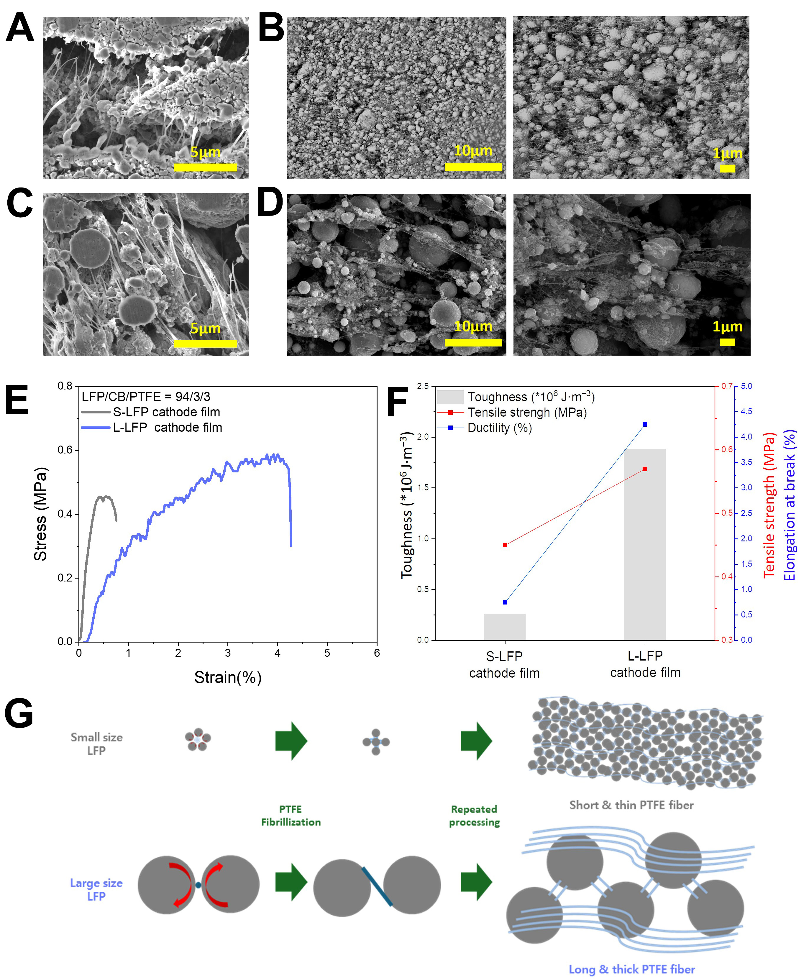
Figure 2. Mechanical properties and microstructure of dry LFP cathodes. SEM images of S-LFP cathode film, (A) cross-sectional view and (B) top view; SEM images of L-LFP cathode film; (C) cross-sectional view and (D) top view; (E) UTM measurement and (F) mechanical properties of dry LFP cathode films; (G) Schematic illustration of PTFE fiber network within dry LFP cathodes. LFP: LiFePO4; S-LFP: small-sized LFP; L-LFP: large-sized LFP; SEM: scanning electron microscopy; UTM: universal testing machine.
Two-step extrusion process for fabrication of LFP dry cathode film
To improve the flexibility and mechanical robustness of nano-sized LFP dry cathode films, we introduced a two-step extrusion process to facilitate the formation of a thick and long PTFE fiber network within the nano-sized LFP matrix. This two-step process was specifically designed to overcome the limitations of conventional dry processing, in which all components-LFP, CNT, and PTFE-are mixed, extruded, ground, and calendered in a single sequence. The CNTs were employed as conductive agents, not only to enhance electronic conductivity but also to contribute to the formation of a fiber network within the electrode due to their one-dimensional (1D) morphology[35]. As shown in the schematic illustration, the developed two-step extrusion process is divided into two stages [Figure 3A]. In the 1st stage, LFP is dry mixed with half of the total amount of CNT and half of the total amount of PTFE, followed by extrusion and grinding to form the 1st granules. Within the 1st granules, short and thin PTFE fibers were formed between closely packed
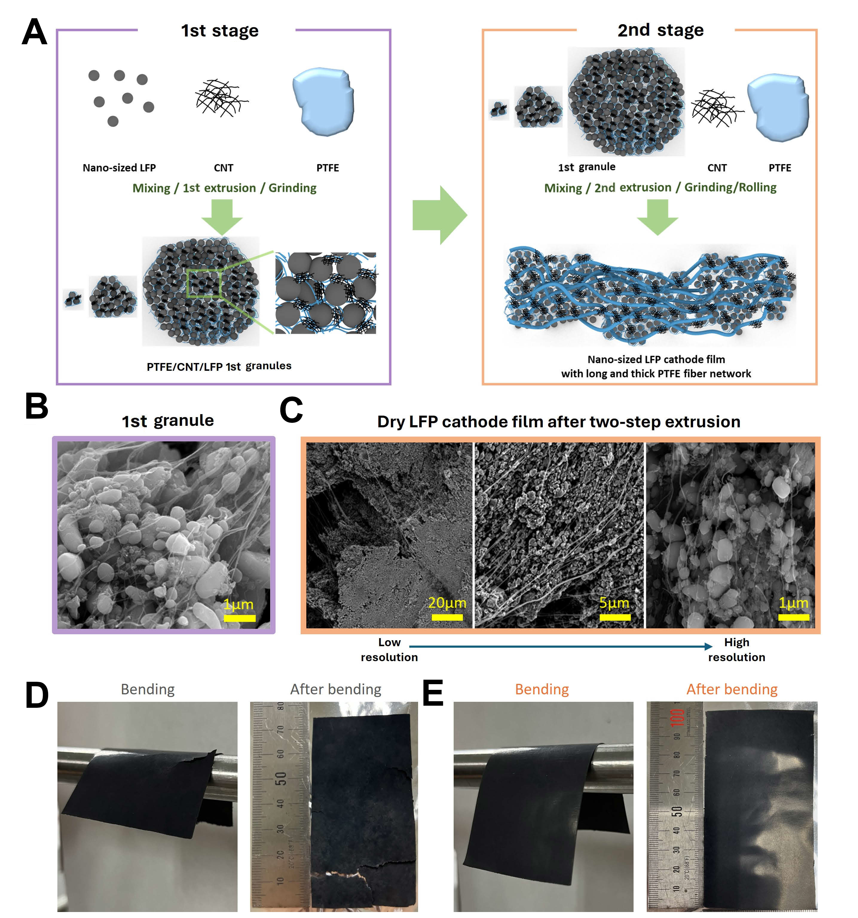
Figure 3. Two-step extrusion process for fabrication of dry LFP cathode film. (A) Schematic illustration of the two-step extrusion process for fabrication of dry LFP cathodes; left: 1st stage, right: 2nd stage; SEM images of (B) 1st granule after 1st stage and (C) cathode film after 2nd stage from low to high resolution; Digital images of (D) S-LFP cathode film and (E) D-LFP cathode film according to the bending test. LFP: LiFePO4; SEM: scanning electron microscopy; S-LFP: small-sized LFP; D-LFP: developed LFP via two-step extrusion process.
Mechanical properties and microstructure of LFP dry cathode films
To verify the enhancement of mechanical properties achieved via the two-step extrusion process, UTM and micro-indentation measurements were conducted on S-LFP and D-LFP dry cathode films with a composition ratio of LFP:CNT:PTFE = 94:3:3. The UTM results showed that the tensile strength of D-LFP was slightly higher (0.41 MPa) than that of S-LFP (0.39 MPa) [Figure 4A and Supplementary Figure 10]. In contrast, the difference in elongation at break was more pronounced: D-LFP exhibited a value of 2.9%, more than twice that of S-LFP, indicating a substantial improvement in ductility, attributed to the formation of a long and thick PTFE fiber network. As a result, the toughness of D-LFP achieved 0.75 × 10⁶ J m-3-more than double the value of S-LFP (0.30 × 10⁶ J m-3)- indicating a significantly higher amount of mechanical energy required to reach fracture [Supplementary Figure 11][36,37]. Moreover, the micro-indentation results supported these findings. Under a constant load of 3 N, the indentation depth of D-LFP was 44 µm, compared to 51 µm for S-LFP, suggesting an increased resistance to deformation and enhanced mechanical robustness, associated with the robust PTFE fiber network formed during the 2nd stage [Figure 4B and Supplementary Figure 12]. Then, three types of LFP dry cathode films-S-LFP, D-LFP, and L-LFP-were fabricated with a composition of LFP:CNT:PTFE = 94:4:2 (by weight), to evaluate the mechanical properties under reduced binder content. The S-LFP dry cathode films were extremely brittle and exhibited poor
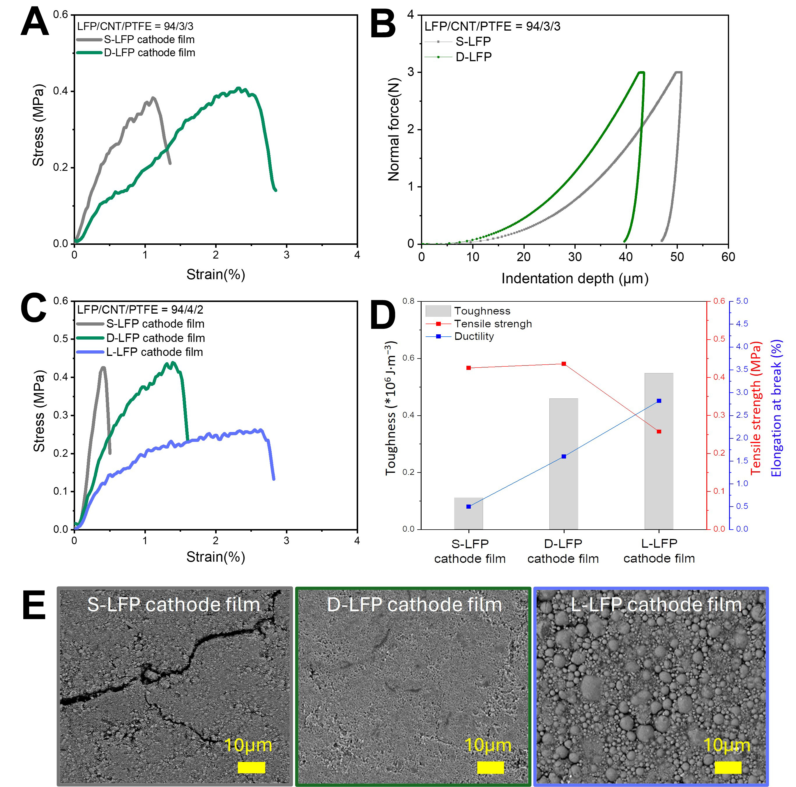
Figure 4. Mechanical properties and microstructure of dry LFP cathode films. (A) Stress-strain curve from UTM measurement and (B) micro-indentation test of dry LFP cathode films (LFP/CNT/PTFE = 94/3/3); (C) Stress-strain curve and (D) mechanical properties from UTM measurement; (E) Top view SEM images of dry LFP cathode films (LFP/CNT/PTFE = 94/4/2); left: S-LFP cathode film, middle:
Electrochemical performance of LFP dry cathodes
The effect of improved mechanical integrity and microstructure on the electrical resistance and electrochemical performance of nano-LFP dry cathodes was investigated by fabricating three types of LFP dry cathodes-S-LFP, D-LFP, and L-LFP-with a fixed composition of LFP:CNT:PTFE = 94:4:2, an areal capacity of 7 mAh cm-2, and an electrode density of 2.7 g cm-3. The sheet resistance of LFP dry cathodes was measured using a four-point probe method [Figure 5A][38,39]. The S-LFP electrode exhibited a high sheet resistance of 11.97 Ω sq-1, more than three times greater than those of the D-LFP and L-LFP electrodes. Additionally, S-LFP showed large standard variations in resistance values, likely due to localized cracks observed in its top-view SEM images. In contrast, the D-LFP and L-LFP dry cathodes exhibited consistently low sheet resistance values with low standard variations, indicating that the well-formed, thick and long PTFE fiber networks ensured good interparticle adhesion and preserved continuous electronic pathways. These differences in electrical resistance were reflected in the rate capability test, evaluated using a half-cell configuration. During the formation condition (1st cycle at 0.1C-rate charge/discharge), no significant difference in initial capacity or coulombic efficiency was observed across the three LFP dry cathodes [Figure 5B]. However, as the discharge rate increased, the S-LFP dry cathode showed a steep degradation in discharge capacity, while D-LFP and L-LFP dry cathodes maintained a stable discharge capacity up to 0.5C rate. Beyond 1.0C rate, the L-LFP dry cathode began to exhibit noticeable degradation in discharge capacity compared to the D-LFP dry cathode. At 1.5C rate, the discharge areal capacity of the D-LFP dry cathode remained at approximately 4 mAh cm-2, whereas that of the L-LFP dry cathode dropped to ~3.5 mAh cm-2, likely due to limitations in Li-ion kinetics within the L-LFP dry cathode, stemming from the large particle size of LFP [Figure 5C]. To verify this, EIS was conducted at 50% state of charge (SOC) using a half-cell configuration [Figure 5D][40]. The L-LFP dry cathode exhibited a significantly higher Li-ion resistance of 6.60 Ω, compared to ~4.1 Ω for both D-LFP and S-LFP dry cathodes. Considering the intrinsically low ionic conductivity of LFP, larger particle sizes increase diffusion pathways and reduce Li-ion kinetics, particularly under high current densities, thereby resulting in lower discharge capacities. These results highlight the critical role of particle size of LFP in governing Li-ion kinetics, underscoring the necessity of applying
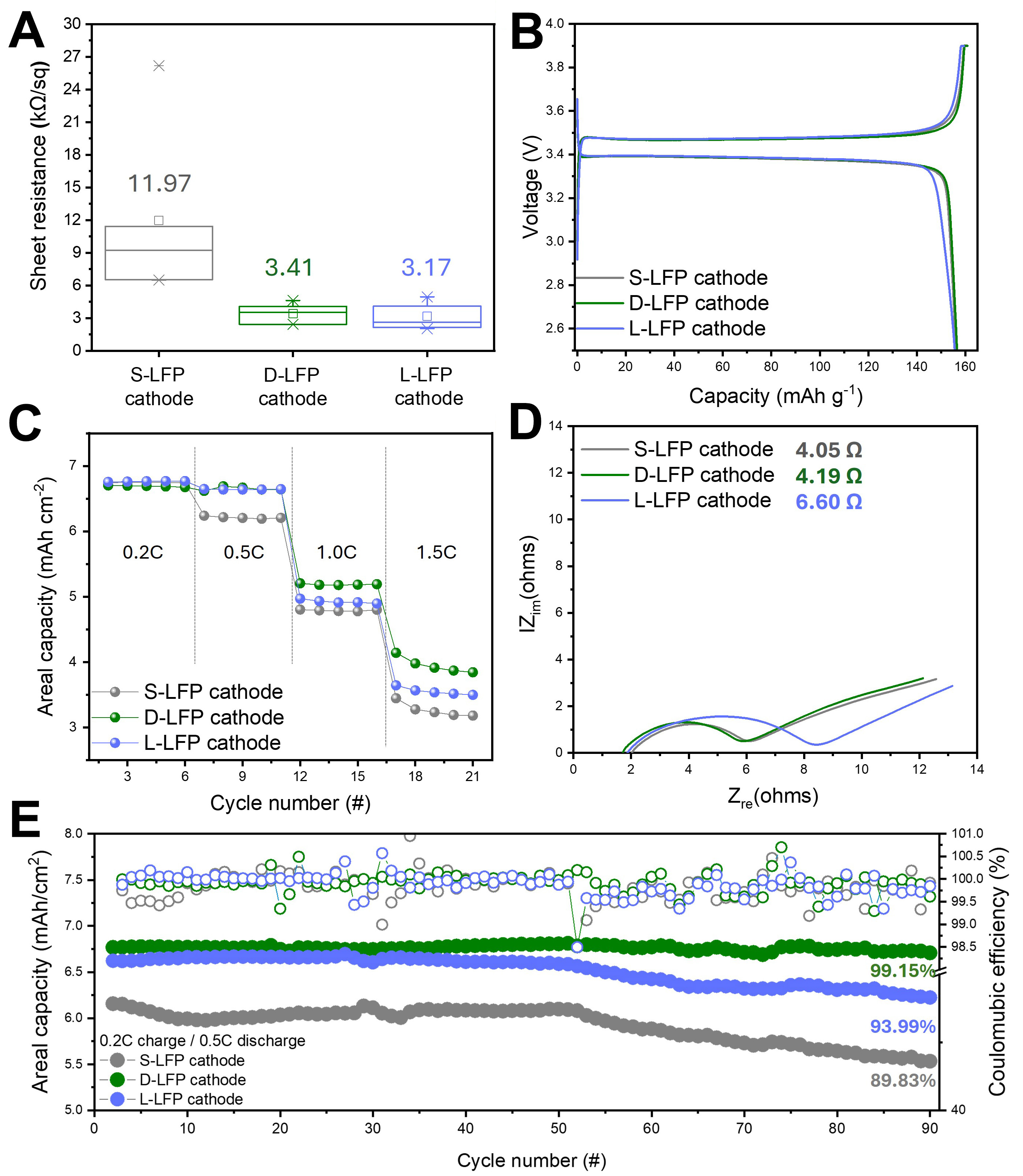
Figure 5. Electrochemical performance of dry LFP cathodes with 7 mAh cm-2. (A) Sheet resistances of dry LFP cathode films; (B) The 1st cycle voltage profiles and (C) rate capability; (D) Li-ion resistance from EIS measurement at SOC 50% and (E) cycle performances at 0.2C-rate charge and 0.5C-rate discharge. LFP: LiFePO4; EIS: electrochemical impedance spectroscopy; SOC: state of charge.
Nevertheless, despite the significant improvements, the mechanical properties of nano-sized LFP dry cathodes still fall short compared to those of dry cathodes based on high-nickel cathode or graphite anodes. These limitations continue to pose challenges for the application of roll-to-roll dry coating processes. Future research should, therefore, focus on further enhancing the mechanical properties of nano-sized LFP dry cathodes. In particular, materials-level innovations, when combined with advanced process engineering, will be essential to fully unlock the potential of nano-LFP dry cathodes for scalable, high-performance lithium-ion batteries.
CONCLUSION
In this study, we developed a simple yet effective two-step extrusion process to control the distribution and morphology of PTFE fibers within nano-sized LFP dry cathode films, without modifying the material composition. This process-driven approach enabled the formation of a dual-scale PTFE fiber
DECLARATIONS
Authors’ contributions
Conceptualization, writing - original draft: Kim, J.; Kim, M.
Experiments and data collection: Han, S.
Supervision, review and editing: Paik, U.; Song, T.
Availability of data and materials
The datasets supporting the findings of this study are included within the article and its Supplementary Materials files. Further data are available from the corresponding authors upon reasonable request.
Financial support and sponsorship
This work was supported by the Technology Innovation Program (or Industrial Strategic Technology Development Program-Materials & Components Technology Development Program) (20024261, Development of thick film electrode and cell manufacturing technology for high-performance lithium iron phosphate battery with energy density of over 200 Wh/kg) funded By the Ministry of Trade, Industry & Energy (MOTIE, Korea). This work was also supported by the Technology Innovation Program (00429527, Development of high-density thick-film Lithium Manganese Iron Phosphate electrode manufacturing technology through application of functional conductive materials) through the Korea Planning & Evaluation Institute of Industrial Technology (KEIT) funded by the Ministry of Trade, Industry & Energy (MOTIE, Korea). This work was also supported by Samsung SDI.
Conflicts of interest
All authors declared that there are no conflicts of interest.
Ethical approval and consent to participate
Not applicable.
Consent for Publication
Not applicable.
Copyright
© The Author(s) 2026.
Supplementary Materials
REFERENCES
1. Yang, Z.; Huang, H.; Lin, F. Sustainable electric vehicle batteries for a sustainable world: perspectives on battery cathodes, environment, supply chain, manufacturing, life cycle, and policy. Adv. Energy. Mater. 2022, 12, 2200383.
2. Frith, J. T.; Lacey, M. J.; Ulissi, U. A non-academic perspective on the future of lithium-based batteries. Nat. Commun. 2023, 14, 420.
3. Jamil, S.; Wang, G.; Fasehullah, M.; Xu, M. Challenges and prospects of nickel-rich layered oxide cathode material. J. Alloys. Compd. 2022, 909, 164727.
4. Li, W.; Erickson, E. M.; Manthiram, A. High-nickel layered oxide cathodes for lithium-based automotive batteries. Nat. Energy. 2020, 5, 26-34.
5. Nekahi, A.; Kumar, M. R. A.; Li, X.; Deng, S.; Zaghib, K. Sustainable LiFePO4 and LiMnxFe1-xPO4 (x=0.1-1) cathode materials for lithium-ion batteries: a systematic review from mine to chassis. Mater. Sci. Eng. R. Rep. 2024, 159, 100797.
6. Ramasubramanian, B.; Sundarrajan, S.; Chellappan, V.; Reddy, M. V.; Ramakrishna, S.; Zaghib, K. Recent development in carbon-LiFePO4 cathodes for lithium-ion batteries: a mini review. Batteries 2022, 8, 133.
7. Zhong, Z.; Chen, L.; Zhu, C.; Ren, W.; Kong, L.; Wan, Y. Nano LiFePO4 coated Ni rich composite as cathode for lithium ion batteries with high thermal ability and excellent cycling performance. J. Power. Sources. 2020, 464, 228235.
8. Yang, X.; Liu, T.; Wang, C. Thermally modulated lithium iron phosphate batteries for mass-market electric vehicles. Nat. Energy. 2021, 6, 176-85.
9. Gao, F.; Tang, Z.; Xue, J. Preparation and characterization of nano-particle LiFePO4 and LiFePO4/C by spray-drying and post-annealing method. Electrochim. Acta. 2007, 53, 1939-44.
10. Ji, G.; Wang, J.; Liang, Z.; et al. Direct regeneration of degraded lithium-ion battery cathodes with a multifunctional organic lithium salt. Nat. Commun. 2023, 14, 584.
11. Kuang, Y.; Chen, C.; Kirsch, D.; Hu, L. Thick electrode batteries: principles, opportunities, and challenges. Adv. Energy. Mater. 2019, 9, 1901457.
12. Wu, J.; Zhang, X.; Ju, Z.; et al. From fundamental understanding to engineering design of high-performance thick electrodes for scalable energy-storage systems. Adv. Mater. 2021, 33, 2101275.
13. Boyce, A. M.; Cumming, D. J.; Huang, C.; et al. Design of scalable, next-generation thick electrodes: opportunities and challenges. ACS. Nano. 2021, 15, 18624-32.
14. Chang, J. H.; Pin, M. W.; Kim, I.; et al. Binder migration: frequently observed yet overlooked phenomena in electrode processing for lithium-ion batteries. J. Energy. Storage. 2024, 83, 110729.
15. Lu, Y.; Zhao, C.; Yuan, H.; Hu, J.; Huang, J.; Zhang, Q. Dry electrode technology, the rising star in solid-state battery industrialization. Matter 2022, 5, 876-98.
16. Sung, K.; Hwang, I.; Choi, J.; Jung, S.; Yoon, J. Enhanced adhesion in PTFE-based dry electrodes with hydrogen bonding co-binder integration for advanced lithium-ion batteries. Chem. Eng. J. 2025, 511, 161789.
17. Zhang, K.; Li, D.; Wang, X.; et al. Dry electrode processing technology and binders. Materials 2024, 17, 2349.
18. Kim, J.; Park, K.; Kim, M.; et al. 10 mAh cm-2 cathode by roll-to-roll process for low cost and high energy density Li-ion batteries. Adv. Energy. Mater. 2024, 14, 2303455.
19. Horst, M.; Beverborg, F.; Bahlmann, L.; et al. Effect of active material morphology on PTFE-fibrillation, powder characteristics and electrode properties in dry electrode coating processes. Powder. Technol. 2025, 451, 120451.
20. Wang, X.; Chen, S.; Zhang, K.; et al. A polytetrafluoroethylene-based solvent-free procedure for the manufacturing of lithium-ion batteries. Materials 2023, 16, 7232.
21. Lee, K.; Jo, Y.; Nam, J. S.; Yu, H.; Kim, Y. Dry-film technology employing cryo-pulverized polytetrafluoroethylene binder for all-solid-state batteries. Chem. Eng. J. 2024, 487, 150221.
22. Kang, J.; Eom, H.; Jang, S.; et al. Bollard-anchored binder system for high-loading cathodes fabricated via dry electrode process for Li-ion batteries. Adv. Mater. 2025, 37, 2416872.
23. Zhang, Y.; Lu, S.; Wang, Z.; Volkov, V.; Lou, F.; Yu, Z. Recent technology development in solvent-free electrode fabrication for lithium-ion batteries. Renew. Sustain. Energy. Rev. 2023, 183, 113515.
24. Kwon, K.; Kim, J.; Han, S.; et al. Low-resistance LiFePO4 thick film electrode processed with dry electrode technology for high-energy-density lithium-ion batteries. Small. Sci. 2024, 4, 2300302.
25. Al-Samet, M. A.; Burgaz, E. Improving the lithium-ion diffusion and electrical conductivity of LiFePO4 cathode material by doping magnesium and multi-walled carbon nanotubes. J. Alloys. Compd. 2023, 947, 169680.
26. Naoi, K.; Kisu, K.; Iwama, E.; et al. Ultrafast charge-discharge characteristics of a nanosized core-shell structured LiFePO4 material for hybrid supercapacitor applications. Energy. Environ. Sci. 2016, 9, 2143-51.
27. Luo, Y.; Chen, Y.; Koratkar, N.; Liu, W. Densification of alloying anodes for high energy lithium-ion batteries: critical perspective on inter- versus intra-particle porosity. Adv. Sci. 2024, 11, 2403530.
28. Wiegmann, E.; Fischer, S.; Leeb, M.; Kwade, A. Sustainable lithium ferro-phosphate cathode manufacturing: a semi-dry approach with water-based processing and polytetrafluorethylene binders. Batteries 2023, 9, 567.
29. Kim, B.; Kim, D. K.; Yu, J.; Yoo, Y. Conductive agent-controlled tortuosity in solvent-free thick-film electrodes for high-energy lithium-ion batteries. Energy. Environ. Mater. 2025, e70019.
30. Wang, X. Q.; Chen, D. R.; Han, J. C.; Du, S. Y. Crystallization behavior of polytetrafluoroethylene (PTFE). J. Appl. Polym. Sci. 2002, 83, 990-6.
31. Starkweather, H. W.; Zoller, P.; Jones, G. A.; Vega, A. J. The heat of fusion of polytetrafluoroethylene. J. Polym. Sci. Polym. Phys. Ed. 1982, 20, 751-61.
32. Ferry, L.; Vigier, G.; Vassoille, R.; Bessede, J. L. Study of polytetrafluoroethylene crystallization. Acta. Polym. 1995, 46, 300-6.
33. Jiang, R.; Liu, T.; Xu, Z.; Park, C. B.; Zhao, L. Improving the continuous microcellular extrusion foaming ability with supercritical CO2 of thermoplastic polyether ester elastomer through in-situ fibrillation of polytetrafluoroethylene. Polymers 2019, 11, 1983.
34. Jiang, G.; Hu, Z.; Xiong, J.; Zhu, X.; Yuan, S. Enhanced performance of LiFePO4 originating from the synergistic effect of graphene modification and carbon coating. J. Alloys. Compd. 2018, 767, 528-37.
35. Kim, I.; Choi, J. H.; Jang, H.; et al. Troubleshooting carbon nanotube bundling using electrostatic energy-driven dispersion for LiFePO4 bimodal thick electrode in lithium-ion batteries. ACS. Nano. 2025, 19, 15941-52.
36. Launey, M. E.; Ritchie, R. O. On the fracture toughness of advanced materials. Adv. Mater. 2009, 21, 2103-10.
38. Seidl, C.; Thieme, S.; Frey, M.; Nikolowski, K.; Michaelis, A. Comparison of electronic resistance measurement methods and influencing parameters for LMFP and high-nickel NCM cathodes. Batteries 2024, 10, 105.
39. Li, H.; Peng, L.; Wu, D.; Wu, J.; Zhu, Y.; Hu, X. Ultrahigh-capacity and fire-resistant LiFePO4-based composite cathodes for advanced lithium-ion batteries. Adv. Energy. Mater. 2019, 9, 1802930.
Cite This Article
How to Cite
Download Citation
Export Citation File:
Type of Import
Tips on Downloading Citation
Citation Manager File Format
Type of Import
Direct Import: When the Direct Import option is selected (the default state), a dialogue box will give you the option to Save or Open the downloaded citation data. Choosing Open will either launch your citation manager or give you a choice of applications with which to use the metadata. The Save option saves the file locally for later use.
Indirect Import: When the Indirect Import option is selected, the metadata is displayed and may be copied and pasted as needed.
About This Article
Copyright

Data & Comments
Data
0


Comments
Comments must be written in English. Spam, offensive content, impersonation, and private information will not be permitted. If any comment is reported and identified as inappropriate content by OAE staff, the comment will be removed without notice. If you have any queries or need any help, please contact us at [email protected].