


Heterogeneous twin structure and spontaneous plastic strain evolution in extruded AZ31 Mg alloy under multi-degree-of-freedom reciprocating torsion-compression
 0
0 Abstract
The microstructural evolution and mechanical responses under multi-degree-of-freedom reciprocating torsion-compression deformations remain to be fully elucidated, particularly regarding the Swift and inverse Swift effects and their physical mechanisms, which constrain the design and formability of textured Mg alloys. Therefore, the multi-degree-of-freedom reciprocating pre-torsional-compressive loadings along extrusion direction (ED) were specifically designed. The twinning behaviours and the radial distribution of twin structures were systematically analysed. The driving mechanisms of the Swift and subsequent inverse Swift effects were discussed. Results demonstrated that free end torsion (FET) deformation induced radially linear-gradient twinning structure, while reverse FET (RFET) loading triggered FET twins detwinning and extensive {10
Keywords
INTRODUCTION
Wrought Mg alloy is extensively used in new energy vehicles, aerospace industry and marine engineering because of its outstanding advantages of low density, high specific strength and thermal conductivity, which is in line with the environmental requirements of energy conservation and emission reduction[1-3]. Unfortunately, a strong basal texture is generated during the processing. For instance, the Mg c-axis aligns perpendicular to the extrusion direction (ED) and parallel to the normal direction (ND) during extrusion and rolling processes, respectively[4-7]. The anisotropy of wrought Mg alloys is primarily determined by the difference in the deformation mechanisms activated during plastic deformation of strong textured materials. Among predominant room-temperature deformation modes, basal slip and {10
Researchers have expended considerable effort to weaken the SD effect and anisotropy. A comprehensive review of the existing techniques has been conducted, and the relevant work has mainly focused on: (a) reducing the CRSS difference of the twin/slip systems by grain refinement or precipitation strengthening to inhibit the initiation of {10
Recent research has focused on the regulation of texture by pre-twinning to improve the anisotropy and formability in Mg alloys. Yang et al. engineered a forged Mg-6.5Zn alloy with stratified dual-textured microstructure through extrusion-brief annealing-re-extrusion sequences, exhibiting constrained tension-compression asymmetry[27]. Song et al. introduced tensile twins into rolled AZ31 Mg alloy via side-rolling and reciprocating torsion pre-deformation, where twin-basal duplex textures enhanced basal slip activity during tension along RD[28]. It is imperative to acknowledge the significance of torsional pre-deformation for texture regulation and mechanical enhancement, given its capacity to generate substantial plastic strain while preserving the structural integrity[29]. Solid-rod torsion efficiently produces gradient-structured materials through linear shear strain distribution across cross-sections. It is noteworthy that a specific axial strain exists in the multi-degree-of-freedom torsional deformation [i.e., free end torsion (FET)] of Mg alloy, and this second-order mechanical behaviour is designated as the Swift effect. Swift effect during FET has been conclusively attributed to twin-induced misfit strain accumulation. The texture- and twin-direction sensitivity of Swift effect was demonstrated by Guo et al., the Swift effects of axial shortening and elongation was detected during FET along RD and ND in rolled Mg alloys, respectively[30]. Zhang et al. identified “butterfly”-shaped Swift effect patterns during low-strain cyclic torsion of AZ61 Mg alloy[31]. However, further exploration is required to elucidate the evolution and physical mechanism of the Swift effect under large strain reciprocating FET deformation. Moreover, the influence of large strain reciprocating FET as a pre-twinning technology on the mechanical properties of Mg alloy remains to be clarified, e.g., the mechanical behaviour and microstructure evolution of multi-degree-of-freedom axial deformation after large strain reciprocating FET pre-strain.
Previous investigations of combined axial-torsional deformations have predominantly focused on single-degree-of-freedom modes, with limited exploration of mechanical responses and microstructural evolution under multi-degree-of-freedom axial deformation (i.e., tension/compression permitting circumferential shear strain). Carneiro et al. comprehensively examined the mechanical response and twinning behaviour under combined axial-torsional loads[32]. It is noteworthy that only torsional deformation exhibits multiple degree-of-freedom characteristics in this work. Jiao et al. conducted a systematic examination of the twinning activities during reciprocating FET of AZ31 alloy, thereby identifying the evolution of spontaneous shear strain during subsequent free-rotational tension (FRT)[33]. This circumferential second-order mechanical behaviour was designated the inverse Swift effect. It is well-established that compressive deformation perpendicular to the c-axis maximises the Schmid factor (SFmax = 0.5) for {10
In this research, multi-degree-of-freedom reciprocating torsion-compression tests were specifically designed along the ED of AZ31 Mg alloy to systematically investigate the mechanisms of the initial {10
MATERIALS AND METHODS
Mechanical experiments
The initial material utilised is a commercial extruded AZ31 Mg alloy. Firstly, using the computerised numerical control (CNC) processing technology, the Mg rod with a diameter of 16 mm, was processed into a dog-bone solid rod with a geometric size of Φ6 mm × 9 mm (gauge section) and a diameter of Φ15 mm (clamping section). In order to ensure that the deformation is fully concentrated in the gauge section, the clamping sections were subsequently machined via electro-discharge machining (EDM) into the flattened geometrical configuration. The final specimen geometry and dimensions were illustrated in Figure 1A. Prior to testing, all specimens underwent homogenisation treatment (180 °C, 6 h) to eliminate residual stresses introduced during extrusion or machining, thereby preventing potential interference with experimental results.
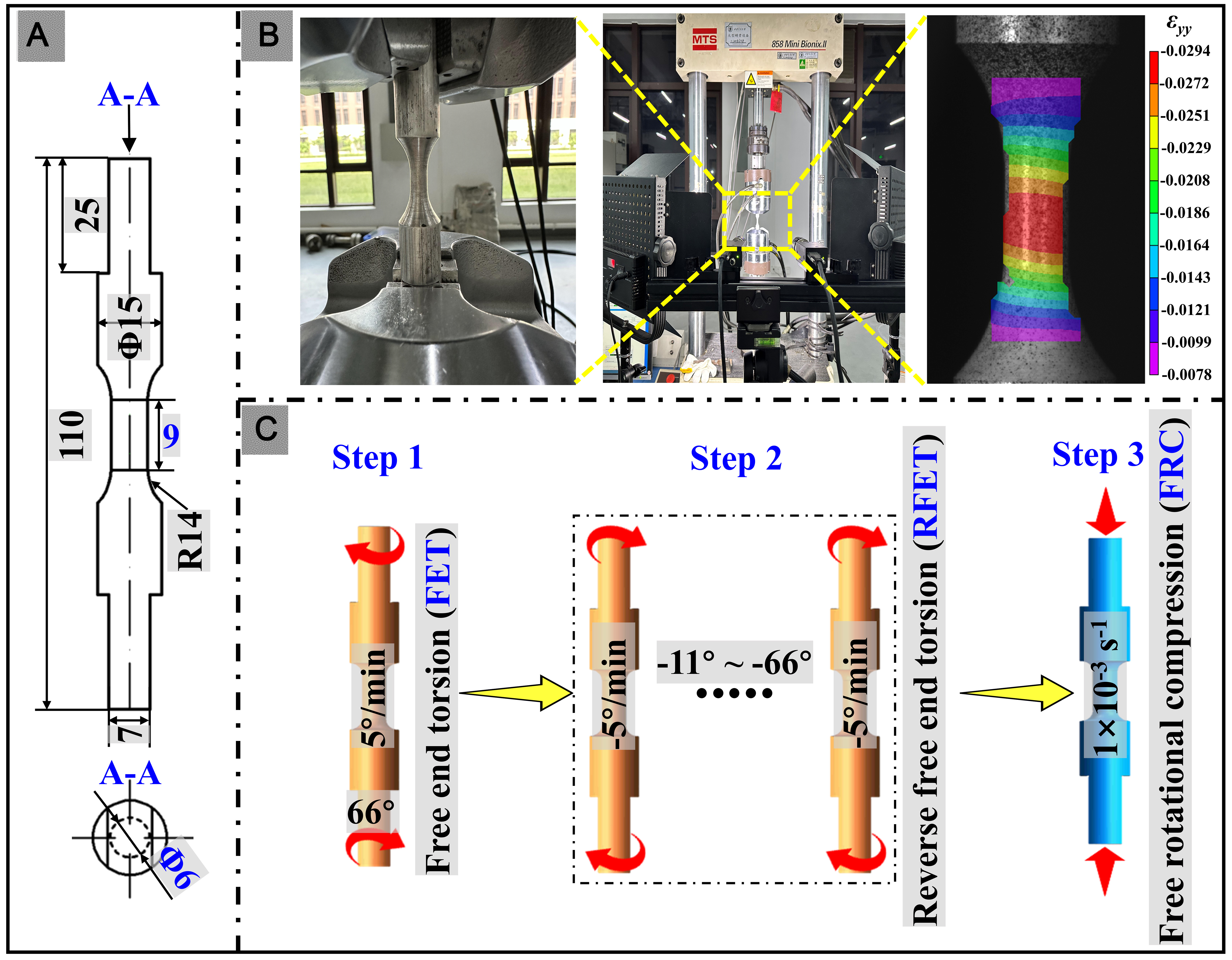
Figure 1. (A) Geometric dimensions of the specimen (unit: mm); (B) Mechanics experiments and strain acquisition; (C) Multi-degree-of-freedom torsion-compression combined loading procedures.
As demonstrated in Figure 1B, the mechanical experiments were conducted on the MTS858 servo-hydraulic biaxial tension-torsion loading system. The MTS858 could achieve combined multi-degree-of-freedom axial-torsional loading modes, i.e. FET that allows axial elongation or shortening, and FRC/FRT that allows circumferential rotation. Figure 1B showed that the geometry of specially designed solid rods could effectively avoid slippage during torsion or axial deformation. The torque and angle during the torsional deformations and the force and displacement during the compressive deformations, were collected by integrated MTS mechanical sensors. Specifically, the torsion angle and displacement in the gauge section were calculated by Equation (1) as the surface shear strain and the average axial strain, respectively. As demonstrated in Equation (2), torque and force during torsion and axial compression were converted into shear and axial stresses[33]. Additionally, based on the torsional and compressive parameters obtained by the MTS mechanical sensor, the initial strain data were corrected according to digital image correlation (DIC) results. The large strain data were calibrated by the auxiliary-line positioning method. Specifically, The axial/shear strains after complete unloading were measured from the incremental displacement/right angle change between the auxiliary lines and the axial lines, respectively.
In Equations (1-2), A0, L0 and R0 denote the initial cross-sectional area, length and radius of the gauge segment, respectively. The shear strain is represented by γSur, whilst the compressive strain is symbolised by ε. The shear stress is denoted by τSur, and the compressive stress by σ. Finally, the φ, ΔL, T and F denote the torsion angle, axial displacement, torque and axial force, respectively.
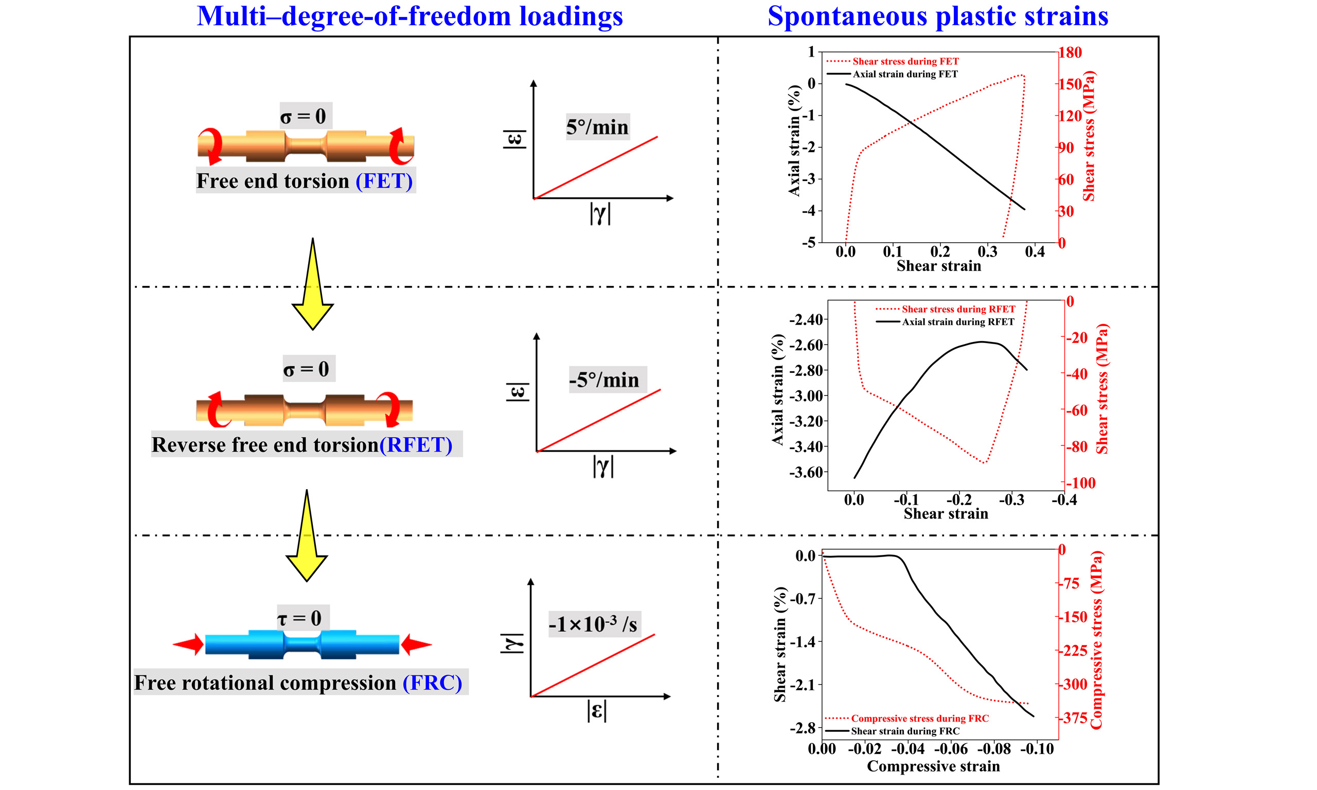
As illustrated in Figure 1C, the multi-degree-of-freedom reciprocating torsional-compressive combined loading procedures were designed for the purpose of detecting the inverse Swift effect and twinning activities. The free-end reciprocating torsion deformations were conducted at an angle control mode of
Mechanical indexes of multi-degree-of-freedom mechanical tests
| Deformation | Specimen | Strain | Velocity |
| FET | FET66 | 0.37 | 5° × min-1 |
| RFET | RFET11 | -0.12 | -5° × min-1 |
| RFET22 | -0.18 | ||
| RFET33 | -0.25 | ||
| RFET44 | -0.31 | ||
| RFET66 | -0.37 | ||
| FRC | FRC5% | -0.05 | -1 × 10⁻³ s-1 |
| FRC11 | -0.1 | ||
| FRC22 | |||
| FRC33 | |||
| FRC44 | |||
| FRC66 |
Mechanical experiments
In order to clarify the twinning activities and microstructure evolutions during reciprocating FET-RFET and subsequent FRC deformations, Electron backscattered diffraction (EBSD) scanning was performed on the cross sections in the middle of the gauge section of the initial and deformed specimens. The scanning areas were subjected to mechanical polishing to a mirror-like surface. Using a commercial AC2 solution and liquid nitrogen, the electropolishing (-20 °C, 15 V, 0.25 A, 2 min) of the EBSD samples was conducted to further remove surface impurities and residual stress. The EBSD tests was performed on a JEOL JSM-7800F field emission scanning electron microscope. The scanning process was controlled by the Oxford HKL Channel 5 system. The operating voltage and distance were 20 kV and 25 mm, respectively. The scanning area was
RESULTS AND DISCUSSION
Initial microstructure
The initial microstructure of the extruded AZ31 Mg alloy was illustrated in Figure 2. As demonstrated in Figure 2A, the inverse pole figure (IPF) revealed that the initial microstructure was composed of equiaxed grains. Furthermore, it was evident that some small grains were surrounded by large grains. The majority of grains were colored green and blue, indicating that the c-axis was perpendicular to ED. Consequently, the pole figure (PF) of the initial microstructure manifested a characteristic annular basal fibre texture. As illustrated in Figure 2B, the mean diameter of the initial grains was 15.7 μm. Twinning and slip were capable of altering the average orientation of grains to varying degrees. As evidenced in Figure 2C, the frequency distribution of the deviation angle (DA) between the grain c-axis and ED was calculated. The c-axis of the majority of grains deviated from ED 75°-90°. Additionally, no initial twin was detected.
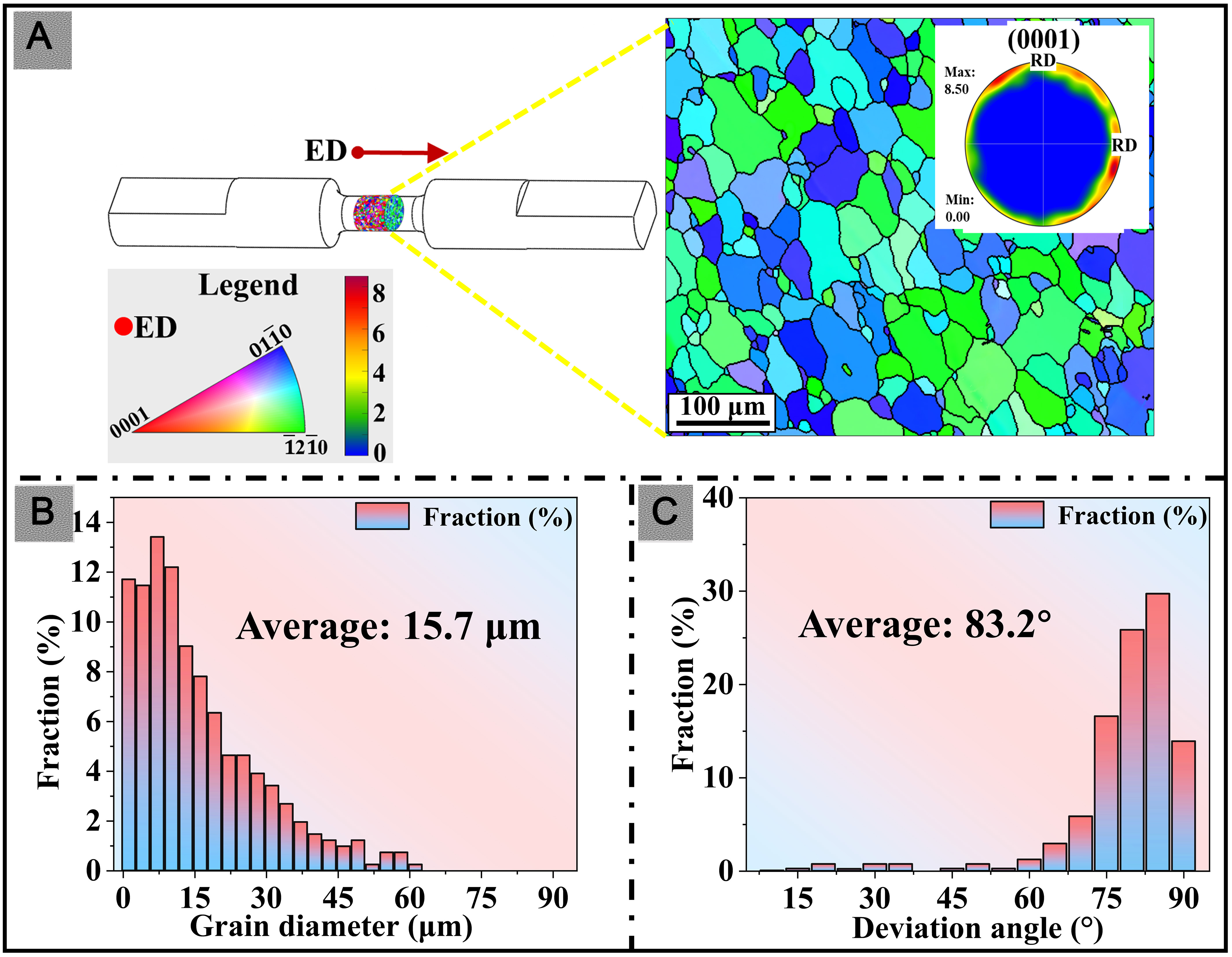
Figure 2. Microstructure of the initial specimen: (A) Inverse pole figure (IPF) and pole figure (PF); (B) Frequency distribution of grain diameter; (C) Frequency distribution map of the deviation angle (DA). ED: Extrusion direction.
Microstructure evolutions
FET and FRC deformations
In order to elucidate the disparity in the physical mechanisms of extruded AZ31 Mg alloy under torsional and compressive loadings, the microstructures of 66° FET and 5% FRC without pre-FET were characterised by EBSD, the observation area is the edge of solid rod. As demonstrated in the IPFs [Figure 3A], tensile twins were identified in the FET66 specimen. In the current study, in order to ascertain the type of twins under various load modes, the superposition maps of matrix grain boundary (GB) and twin boundary (TB) were drawn. Specifically, GB was coloured in black, and the 86° <1
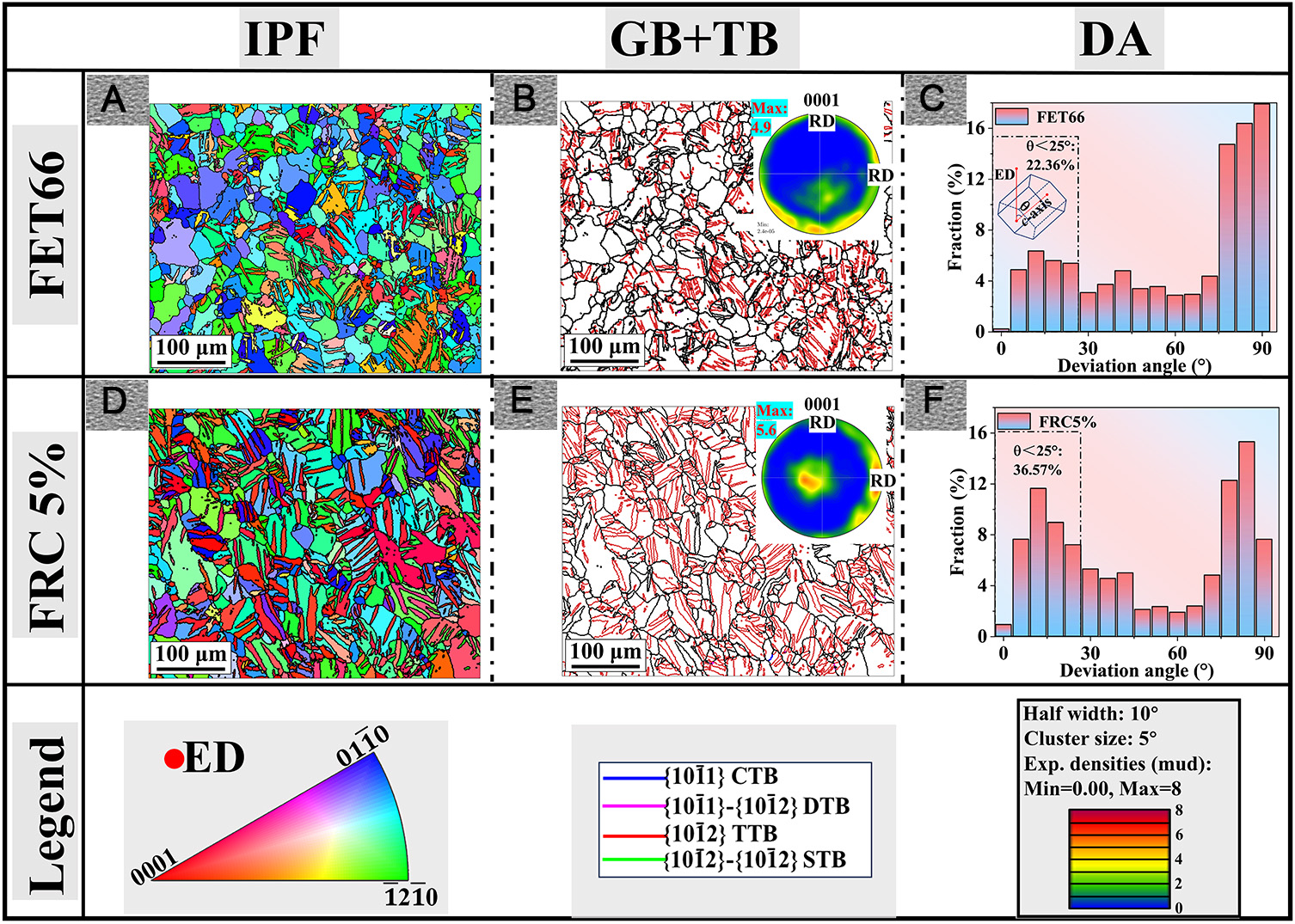
Figure 3. (A and D) IPF maps, (B and E) GB+TB maps and (C and F) DA maps of extruded AZ31 Mg alloy after (A-C) 66° FET and (D-F) 5 % FRC deformations. GB: Grain boundary; TB: twin boundary; IPF: inverse pole figure; FRC: free-rotational compression; FET: free end torsion; RD: rolling direction; ED: extrusion direction; TTB: tensile twin boundary; CTB: compressive twin boundary; STB: secondary twin boundary; DTB: double twin boundary.
It was well established that {10
FRC after RFET deformations
Figure 4 illustrated the microstructure evolution and DA distributions on the edge of solid rod after RFET and subsequent FRC deformations. In comparison with FET66, a decrease in thickness and the number of twins was observed in the specimens (e.g., RFET22 in Figure 4A1 and B1 with low reverse shear strain (γRFET = 0.13). Moreover, the completely twinned grains in Figure 3A almost disappeared. As an inverse process of twinning, detwinning without nucleation could be achieved by purely atomic recombination, which implied that low CRSS was capable of activating detwinning[35]. Therefore, the reversal of the torsional loading promoted the large-scale activation of detwinning, which in turn led to a significant decrease in twin volume fraction (TVF). The twin texture introduced by FET was degraded, and the proportion of DA < 25° was reduced to 11.7%, as evidenced in Figure 4A1 and B1. As the γRFET increased to 0.26, the thickness of the lenticular twins increased [Figure 4A2], indicating that the RFET deformation activated the new {10
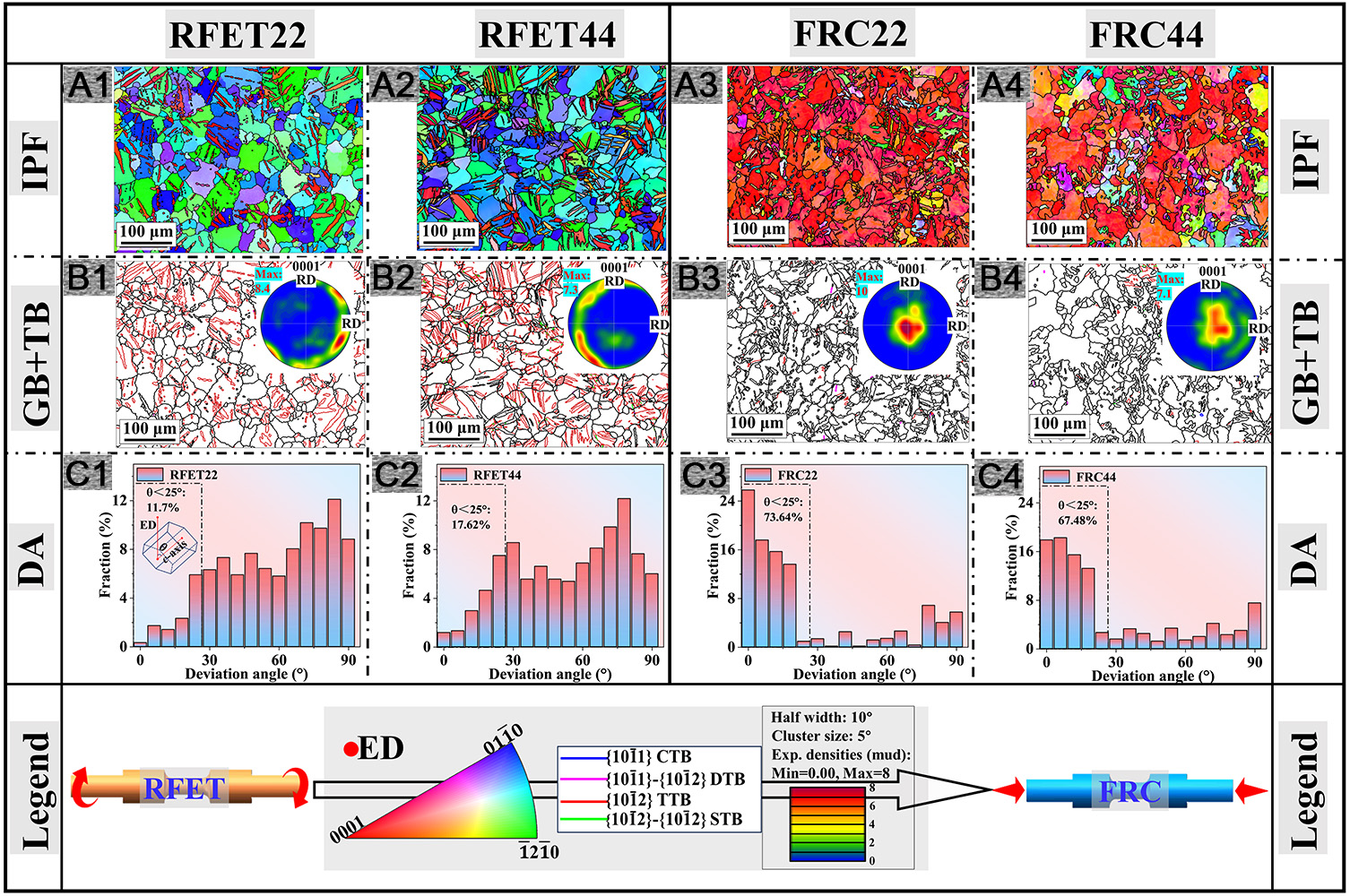
Figure 4. (A1-A4) IPF maps, (B1-B4) GB+TB maps and (C1-C4) DA maps of (A1-C1) RFET22, (A2-C2) RFET44, (A3-C3) FRC22 and (A4-C4) FRC44 specimens. GB: Grain boundary; TB: twin boundary; IPF: inverse pole figure; FRC: free-rotational compression; FET: free end torsion; RD: rolling direction; ED: extrusion direction; RFET: reverse FET; DA: deviation angle; CTB: DTB: TTB: STB
Although the RFET load introduced the new {10
Radial heterogeneous twin structure
Comprehensive analyses were conducted on the radial gradient twin-structure of solid rods under FET loading. However, the effect of the strong interactions between detwinning and RFET twinning on the evolution of radial gradient microstructure under reciprocating FET-RFET load remained to be elucidated. Therefore, the microstructures of the centre (r = 0.3 mm), middle (r = 1.2 mm) and edge (r = 2.7 mm) of the cross section during 66° reciprocating pre-torsion deformations (i.e., FET66-RFET66) were examined. The central region after FET exhibited minimal shear deformation, and a power-function enhancement in shear stress was identified along the radial direction, resulting in a distinctive torsional inhomogeneity of the solid rod[8,31]. A typical linear gradient twin structure was observed in FET66. Due to the reduced plastic shear strain, only a limited number of needle-shaped twins are activated in the central region [Figure 5A1 and A2]. The increase of shear strain promoted the proliferation and growth of tensile twins, and lenticular twins were detected in the middle region, as demonstrated in Figure 5B1 and B2. The TVF (which was equivalent to the area fraction in this study) in the edge region of γFET = 0.38 was further increased, as shown in Figure 5C1 and C2. Previous studies have confirmed that the FET load has the capacity to activate multiple twin variants in the matrix[37], and consistent results were obtained in this study. As illustrated in Figure 5C1, due to the significant misorientation, the twin variants in FET66 were characterised by colours such as orange, red, etc. Consequently, as the FET strain increased, the {10
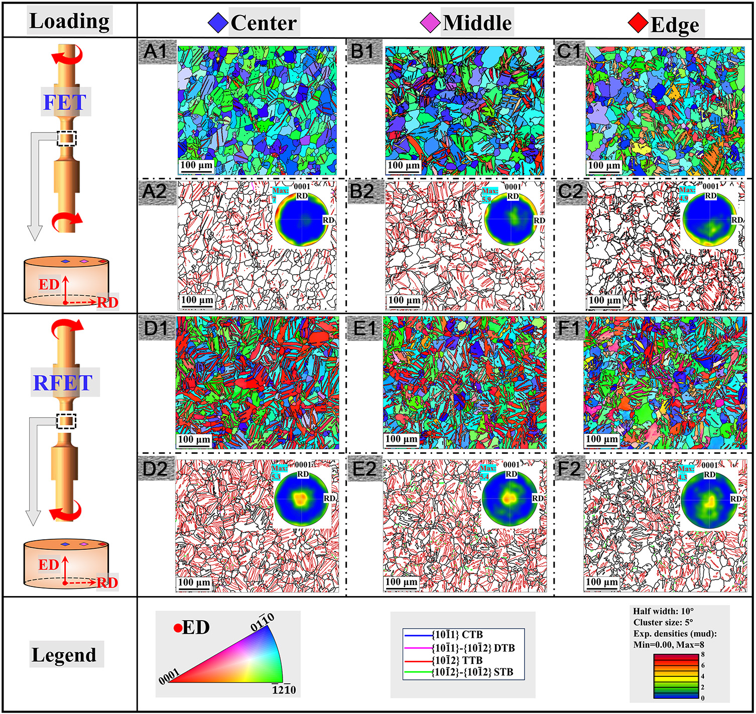
Figure 5. Radial microstructure evolutions of FET66 and RFET66: (A1-A2), (B1-B2) and (C1-C2) are respectively the central, middle and edge EBSD maps of FET66 rod; (D1-D2), (E1-E2) and (F1-F2) are respectively the central, middle and edge EBSD maps of RFET66 rod. GB: Grain boundary; TB: twin boundary; IPF: inverse pole figure; FRC: free-rotational compression; FET: free end torsion; RD: rolling direction; ED: extrusion direction; RFET: reverse FET; DA: deviation angle; TTB: tensile twin boundary; CTB: compressive twin boundary; STB: secondary twin boundary; DTB: double twin boundary.
The IPF maps in Figure 5D1, E1 and F1 depicted the microstructural transition from central to edge regions in the RFET66 rod. Remarkably, compared with FET66, extensive {10
The evolution of the inverse-gradient twin structures following 5% FRC deformation was presented in Figure 6. It is noteworthy that the FRC loading did not induce large-scale {10
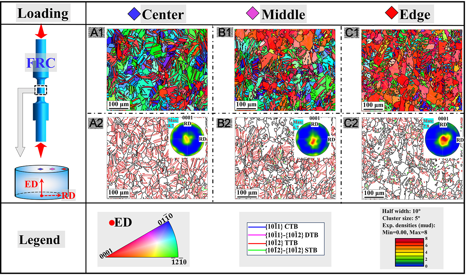
Figure 6. Radial microstructure evolution of FRC22 rod: (A1-A2), (B1-B2) and (C1-C2) are respectively the central, middle and edge EBSD maps. GB: Grain boundary; TB: twin boundary; IPF: inverse pole figure; FRC: free-rotational compression; FET: free end torsion; RD: rolling direction; ED: extrusion direction; RFET: reverse FET; DA: deviation angle; EBSD: electron backscattered diffraction; TTB: tensile twin boundary; CTB: compressive twin boundary; STB: secondary twin boundary; DTB: double twin boundary.
mGSF-based analysis of twinning activities and deformation mechanisms
The mean Schmid factor (MSF) was frequently employed to analyse the potential for activation of various twin/slip systems. However, it should be noted that the MSF method is only applicable for the deformations with clear load directions, such as uniaxial tension or compression. In this study, the global Schmid factor [mGSF, Equation (3)] based on the stress tensor was employed[39]. Moreover, in consideration of the effect of CRSS, the relative activity of twin/slip systems in FET-RFET loadings with composite stress state was evaluated by mGSF/CRSS index.
where mGSF is the global Schmid factor; bT is a specific slip or twinning direction; n denotes the normal direction of slip or twinning plane; σ is the stress tensor under complex loads;
The mean grain orientation of the initial specimen was displayed through (0001)-IPF mapping, as shown in Figure 7A. The mGSF values of all twin/slip system variants in each grain were calculated by MATLAB, and the (0001)-IPF map was coloured according to the range of the maximum mGSF. Figure 7A presents the (0001)-GSF maps for basal slip, prismatic slip, pyramidal slip, and tensile twin during FET of the initial specimen. Within the basal texture, basal and prismatic slip systems exhibited substantially higher mGSF than pyramidal slip and tensile twinning. mGSF/CRSS ratios for each twin/slip system were calculated by employing CRSS values from Wang et al.’s EVPSC-TDT models[40]. Results indicated basal slip and tensile twinning were the primary deformation modes during initial FET due to their low CRSS. Consistency with Guo et al.’s crystal plasticity simulations of FET deformation validated the mGSF/CRSS methodology[29]. Notably, the mGSF/CRSS for tensile twinning was significantly lower than that for basal slip, indicating that the shear plastic strain during FET was mainly accommodated by dislocation slip. This tendency explains the limited {10
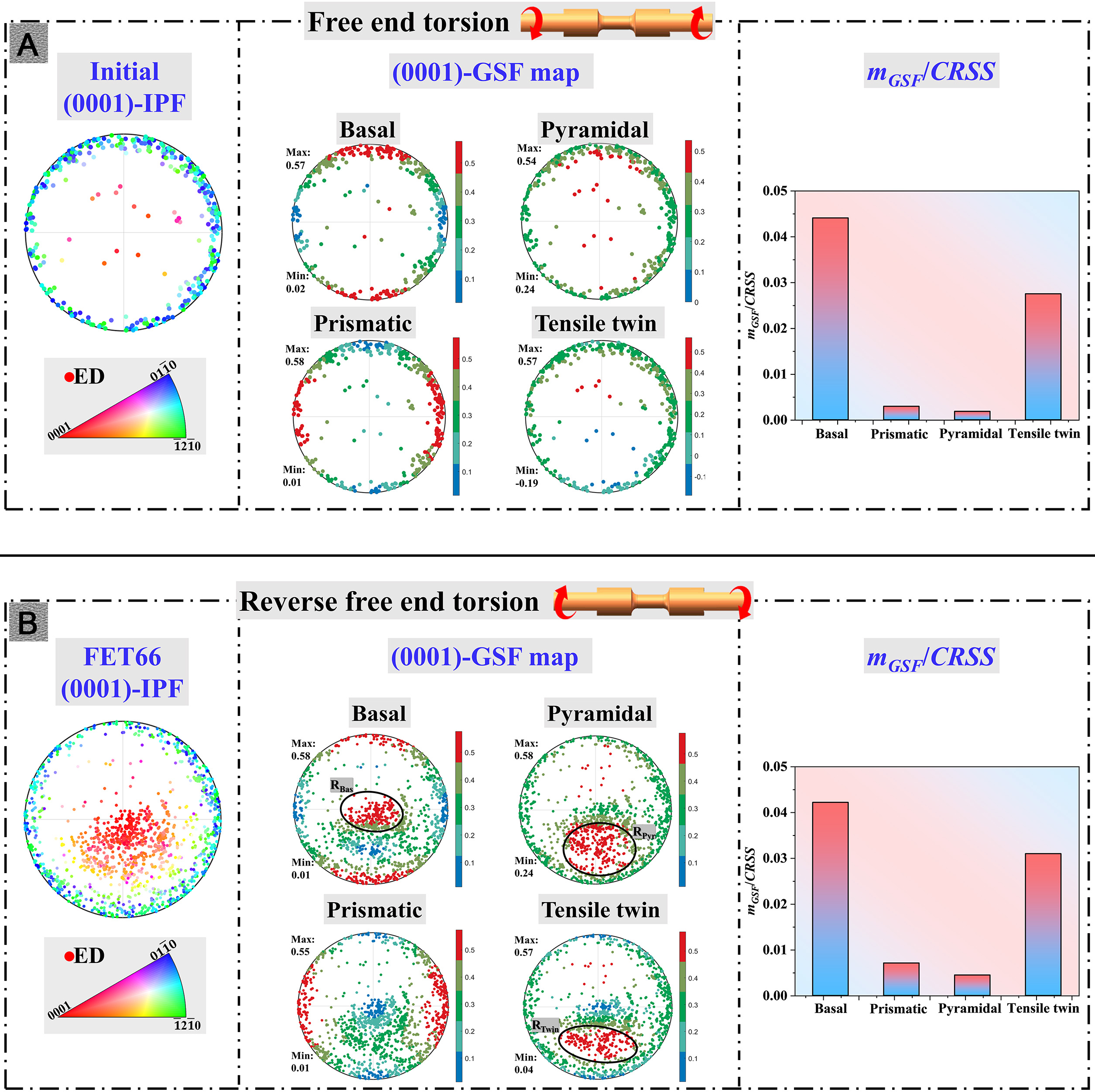
Figure 7. mGSF/CRSS evaluates the activity of the twin and slip systems during (A) FET and (B) RFET, the mGSF is calculated as the average of the maximum mGSF of all grains in (0001)-IPF. CRSS: Critical resolved shear stress; FET: free end torsion; ED: extrusion direction; RFET: reverse FET; mGSF: global Schmid factor.
The bimodal-textured FET66 was employed to investigate potential deformation modes during RFET, as presented in Figure 7B. For slip systems, torsional-load reversal did not change orientation-specific mGSF values. The tensile twin mGSF in the basal texture component of FET66 is reduced to 0.21 compared to the initial texture (~0.26) in Figure 7A. It is attributed to the inhibition of the detwinning behaviour of FET twins on the activation of new tensile twins in RFET. In contrast, intense twin activation propensity was detected within the RTwin domain of the FET-twin textures, resulting from detwinning activities under reverse shear stresses. Moreover, ED-clustered orientations within the FET-twin textures exhibited limited detwinning favourability, indicating that some FET twin variants did not activate the de-twin under reverse loading. Consequently, the residual twin structures in RFET specimen were inferred to comprise a mixture of FET and RFET twins. mGSF/CRSS analysis revealed enhanced activity of prismatic and pyramidal slip systems during RFET, principally arising from the favourable activations for non-basal slips within the twin texture: exemplified by markedly elevated mGSF for pyramidal slip in the RPyr domain. Additionally, although basal slip activity was constrained within the basal texture, elevated mGSF in the RBas domain of the twin texture ensured its continued dominance throughout RFET deformation.
The inverse gradient twin structure observed in the RFET66 specimen is primarily attributable to the disparity in the difficulty of twin activation during reverse torsion, resulting from the heterogeneous distribution of twin texture across the cross-section, which is induced by the positive pre-torsion. Specifically, the positive torsion introduces a radial gradient twin structure, resulting in the twin texture strength of the edge being higher than that of the center. The mGSF/CRSS was employed to evaluate the radial activity of twinning and slip systems in RFET66. As shown in Figure 8, as the proportion of FET twin texture is reduced, the activity of basal slip gradually decreases from the edge to the center, while the tensile twin exhibits the opposite trend. Consequently, the orientation of FET twin texture is not conducive to the initiation of RFET twins. Additionally, given the low CRSS characteristics of detwinning, it is hypothesised that grains containing FET twins undergo preferential activation of detwinning rather than new RFET twinning.
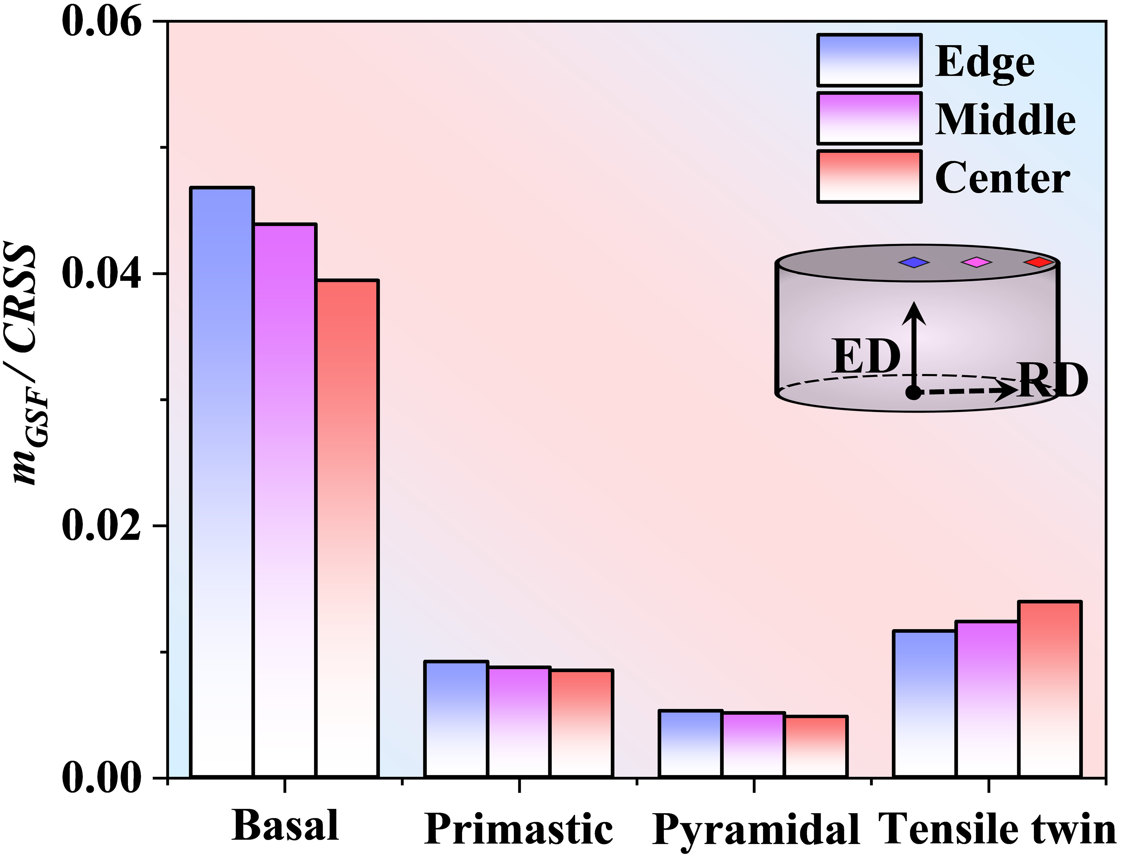
Figure 8. mGSF/CRSS evaluates the radial activity evolution of the twinning and slip systems during RFET. CRSS: Critical resolved shear stress; RD: rolling direction; ED: extrusion direction; RFET: reverse free end torsion; mGSF: global Schmid factor.
Figure 9 illustrated the mGSF distribution of twin/slip systems during FRC deformation in the RFET22 specimen. The mGSF/CRSS of non-basal slip systems was observed to be further increased, which was inferred to result from localised stress concentrations induced by interactions between FRC twins and residual RFET twins. FRC loading perpendicular to the c-axis maximised twinning propensity within the basal texture, whereas basal slip was preferentially activated in orientations deviating 45° from the ED. The increased basal texture fraction following RFET deformation caused tensile twinning to supersede basal slip as the dominant mechanism during FRC.
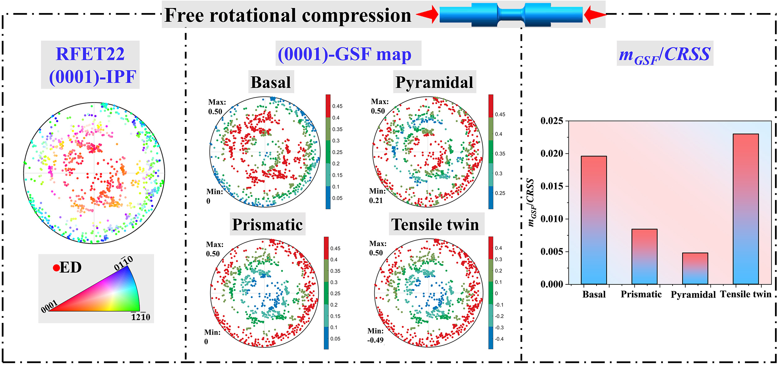
Figure 9. mGSF/CRSS evaluates the activity of the twin and slip systems during FRC, the mGSF is calculated as the average of the maximum mGSF of all grains in (0001)-IPF. CRSS: Critical resolved shear stress; FRC: free-rotational compression; IPF: inverse pole figure; ED: extrusion direction; mGSF: global Schmid factor.
Mechanical responses during reciprocating FET-RFET and FRC loadings
The stress-strain responses under multiple-pass combined FET-RFET-FRC loadings at various elevation angles were presented in Figure 10A-E. Prior researches established that twinning-dominated plastic deformation exhibited distinctive S-shaped stress-strain curves, whereas slip- dominated mechanisms produced characteristic concave-down shape[41]. Despite confirmed {10
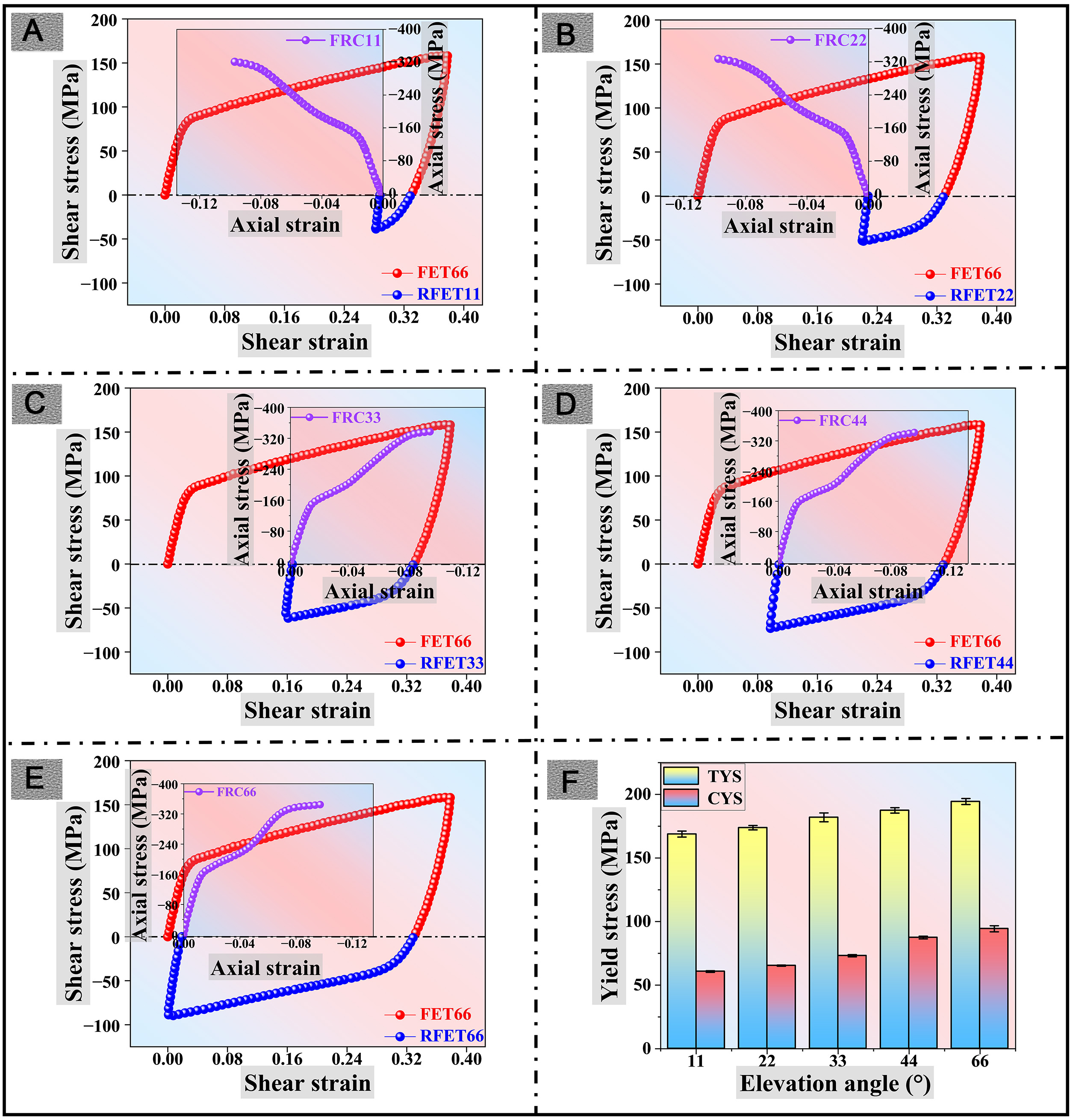
Figure 10. Mechanical responses under combined reciprocating free end torsion (FET-RFET) and subsequent FRC multi-pass loadings: (A) FET66-RFET11-FRC11; (B) FET66-RFET22-FRC22; (C) FET66-RFET33-FRC33; (D) FET66-RFET44-FRC44; (E) FET66-RFET66-FRC66. (F) Tensile and compressive yield stresses under various elevation angles. FET: Free end torsion; RFET: reverse FET; FRC: free-rotational compression; TYS: tensile yield strength; CYS: compressive yield strength. Error bars denote the mean absolute error (MAE), calculated from three independent measurements. All experiments were conducted in triplicate.
The pronounced S-shaped stress-strain curves indicated preferential {10
Mechanical performances of RFET11-66 specimens
| Specimen | σ-10% (MPa) | TYS (MPa) | CYS (MPa) | SD effect |
| RFET11 | -322.02 | 168.8225 | 60.7219 | 0.35968 |
| RFET22 | -328.42 | 173.8328 | 65.3382 | 0.37587 |
| RFET33 | -337.13 | 181.9638 | 73.1395 | 0.40195 |
| RFET44 | -342.15 | 187.4337 | 87.4483 | 0.46656 |
| RFET66 | -344.65 | 194.3917 | 94.3392 | 0.4853 |
Second-order mechanical behaviours
Swift effects during reciprocating FET-RFET
The atomic shuffling of the matrix during the twin shear process, induced by the specific lattice constant of Mg atoms (c/a = 1.624), resulted in the generation of misfit strain. The subsequent accumulation of misfit strain leads to the macroscopic axially shortened Swift effect. As shown in the red curve of Figure 11A, the axial strain of the FET reaches -3.96% at γFET = 0.38. Axial elongation was detected during initial RFET stages (Figure 11A, blue curve), demonstrating markedly nonlinear evolution compared to FET at large γRFET. The velocity evolution of Swift effects throughout FET-RFET was examined via d(%ε)/dγ [Figure 11B]. In the initial stage (γ < 0.1) of the FET, the axial-shortening speed underwent a gradual increase and reached a state of stability with the increasing γFET. In contrast, the RFET load activated axial elongation with a decreasing speed. When the absolute shear strain reaches 0.38, the direction of the Swift effect reversed again, and the Mg rod exhibited axial shortening deformation with an increasing speed.
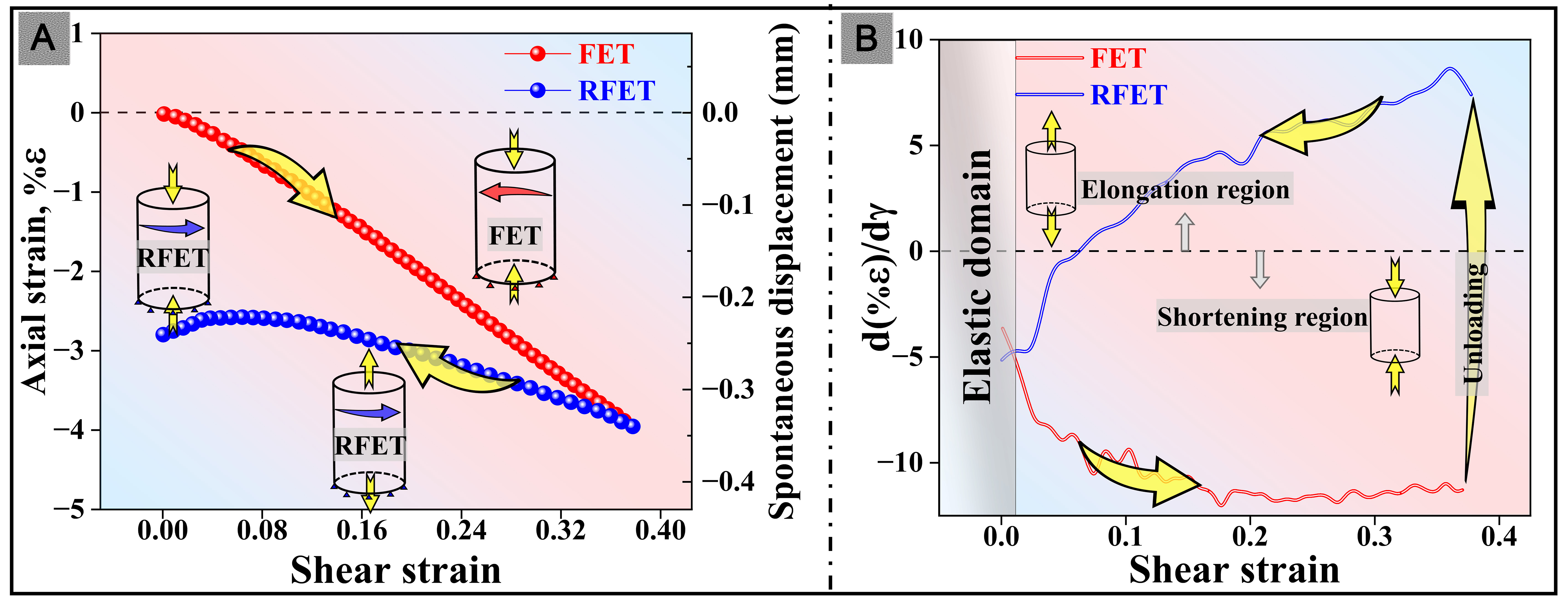
Figure 11. (A) Axial strain (%ε) as a function of shear strain to evaluate the evolution of the Swift effect during reciprocating free-end torsion (FET-RFET); (B) Velocity evolution of the Swift effect is evaluated by d(%ε)/dγ. FET: Free end torsion; RFET: reverse FET.
The initial texture of the matrix, twinning direction and TVF jointly determined the axial stain and direction of the Swift effect during FET. The contribution of twins to the Swift effect was quantitatively analysed by εmisfit/εaxial. The misfit strain dominated by {10
The TVFs at various shear strains throughout FET-RFET processes were statistically analysed, as represented in Figure 12. TVF progressively approached saturation with increasing γFET, while the detwinning led to a decrease in TVF at the initial stage of RFET. It was hypothesised that the detwinning behaviours of the initial FET twins inhibited the initiations of RFET twins to a certain extent. As the number of FET twins decreased, the RFET load activated a larger scale of new {10
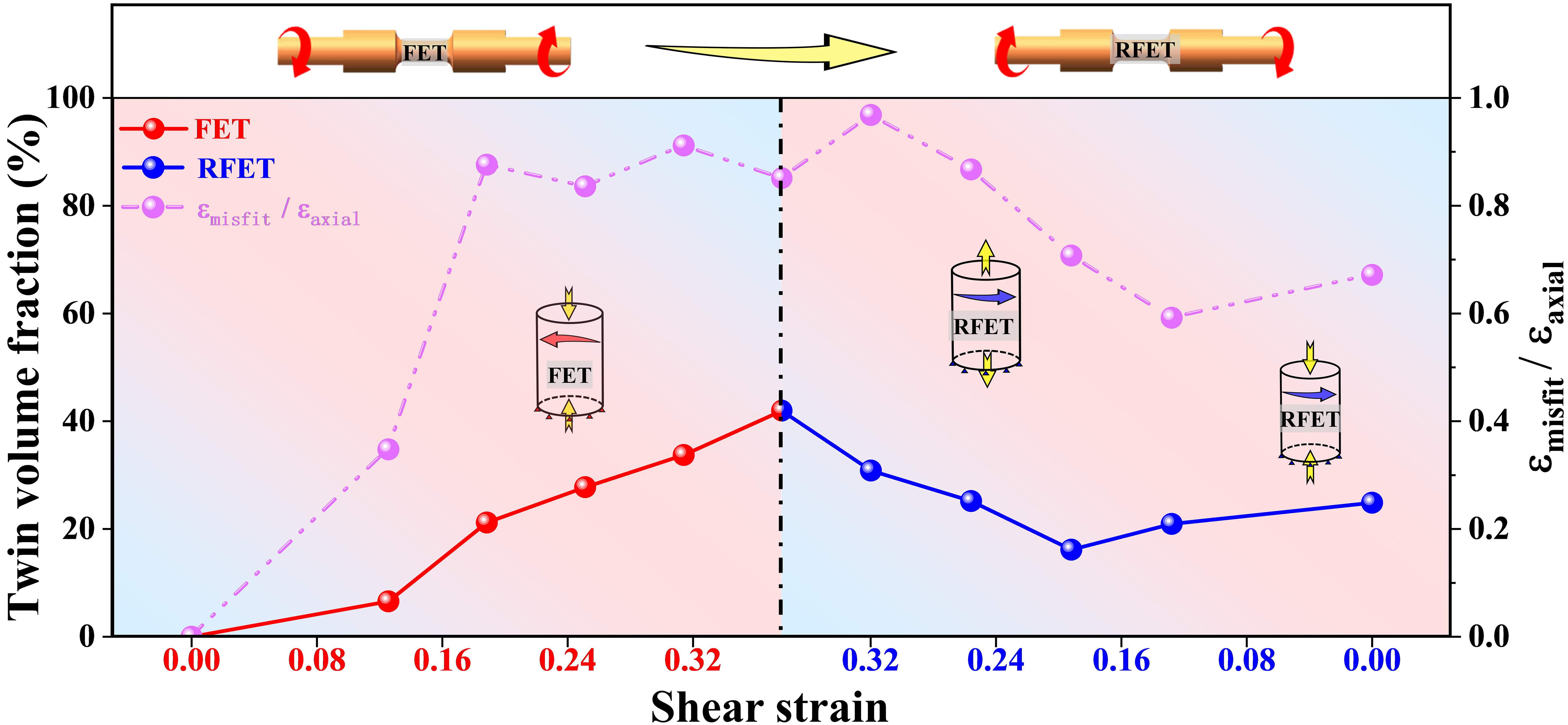
Figure 12. Evolution of TVF and the ratio of twin-dominated misfit strain to axial strain during the reciprocating free end torsion (FET-RFET). FET: Free end torsion; RFET: reverse FET; TVF: twin volume fraction.
Inverse Swift effect during FRC
The Inverse Swift effect was determined by evaluating the evolution of shear strain (%) during FRC. Figure 13A showed the evolution of the inverse Swift effect during FRC deformations after various γRFETS. Prior investigations established that the initial rotational direction of the inverse Swift effect was governed by the residual shear stress distribution within pre-torsional solid rods[43]. Specifically, unidirectional FET generated the residual shear stress fields opposing the original FET direction, inducing the spontaneous reverse rotation during the low-strain FRT to facilitate stress relaxation. Contrastingly, positive rotation was detected during initial FRT after reciprocating FET-RFET, which is a consequence of the reversal of the residual shear stress field caused by the RFET load[33]. The inverse Swift effect under FRC loading exhibited a distinctly two-stage evolutions. In the initial FRC, no circumferential rotation behaviour was observed in the solid rod. As demonstrated in Figure 13A, the circumferential “stationary” process during FRC was positively correlated with γRFET. As the compressive strain increases, negative shear strain (i.e. spontaneous reverse rotation) was detected. Rotational speed and directionality were characterised via d(%γ)/dε [Figure 13B]. In addition to the initial circumferential stationary condition [d(% γ))/d(ε) = 0] was captured, the reverse rotation process was subdivided into two stages according to the rotational speed: an initial rapid acceleration stage, where rotational speed diminished with the increase of γRFET at equivalent absolute FRC strains, followed by the reverse rotation with a constant speed.
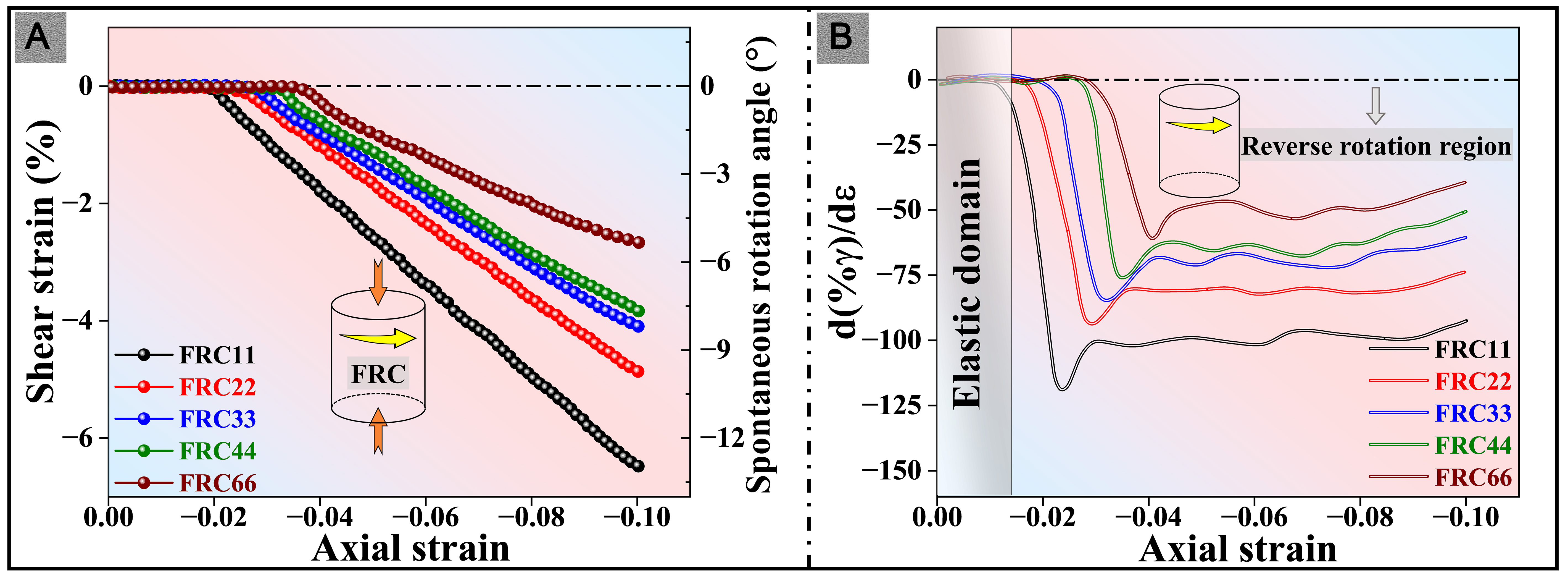
Figure 13. (A) Shear strain (%γ) as a function of axial strain to evaluate the evolution of the inverse Swift effect during FRC along ED; (B) Velocity evolution of the inverse Swift effect is evaluated by d(%γ)/dε. FRC: Free-rotational compression; ED: extrusion direction.
In contrast with the FRT deformation following reciprocating pre-torsion, no spontaneous rotation was detected in the initial FRC stage across varying reverse shear pre-strains. Although FET-RFET loadings generated a radial inverse-gradient twin structure, dislocation slip remained the dominant mechanism for FRT-strain accommodation in the matrix orientation with high proportion characteristics. Conversely, grains with matrix orientation exhibited maximal twinning propensity under FRC loading, with basal and prismatic slip activation being suppressed to a certain extent. Extensive FRC-twin activation facilitated intragranular residual strain energy releasement while ameliorating stress concentrations at matrix GBs[44]. The reorientation of FRC twins to the matrix provided misfit strains that accommodated axial shortening (parallel to ED), concurrently introduced shear strain components perpendicular to ED. Furthermore, asymmetric initial texture distribution [Figure 2A] exacerbated circumferential heterogeneity in twin activation across the matrix. Consequently, FRC-twin proliferation was inferred to promote cumulative circumferential shear strains, which led to the macroscopic reverse spontaneous rotation of solid rod. Nevertheless, the release of circumferential residual shear stress inhibited the reverse spontaneous rotation caused by FRC twins to a certain extent. The interactions between twin shear and residual stresses induced the circumferential motionlessness observed during initial FRC. The residual shear stress following complete elastic unloading was enhanced by increasing γRFET, which also caused more FRC twins to be activated to balance the residual shear stress. Consequently, the circumferential motionlessness in the initial FRC exhibited a positive correlation with the γRFET, as illustrated in Figure 13.
As the residual shear stress induced by the reciprocating FET-RFET was ehausted, the reverse spontaneous rotation driven by the tensile twin dominated the circumferential deformation. It was confirmed that the detwinning of residual twins after FET-RFET deformation promoted the reverse rotation during FRT[33]. Consequently, the detwinning of partial twin texture under FRC loading resulted in the increase of reverse rotational speed. However, due to the low proportion of twin texture and the high activity of detwinning, the accelerated reverse rotation process was brief. With the proportion of twin texture decreased, tensile twinning and basal slip jointly coordinated the circumferential and compressive strains.
CONCLUSIONS
In this study, the microstructure evolutions and mechanical responses of extruded AZ31 Mg alloy under multi-degree-of-freedom reciprocating pre-torsion-compression loading were analysed by specially designed FET-RFET loadings with various shear pre-strains and subsequent FRC tests. In particular, the radial evolution of twinning behaviours and twin structure were systematically elucidated, the physical mechanisms of Swift effect under large strain reciprocating FET-RFET and the inverse Swift effect during FRC were discussed. The main conclusions are as follows:
1. Compared with the linear gradient twin structure on the cross section introduced by FET deformation, a distinctive inverse-gradient twin structure was obtained by reciprocating FET-RFET, which was attributed to the inhibitions of FET twins on RFET-twin nucleation.
2. The γRFET was primarily coordinated by basal slip and detwinning. mGSF analysis demonstrated that the FET-twin variants oriented towards ED exhibited the lowest detwinning favourability under RFET load. The initial plastic deformation of the FRC was dominated by {10
3. The Swift effect exhibits multi-directionality during FET-RFET. The 65% axial-shortening during the low-strain FET (γ < 0.12) was attributed to dislocation slip. Tensile twinning accommodated more than 85% of the Swift effect under the large shear strain. The detwinning of the initial RFET dominated almost all of the axial elongation strain. The large-scale activation of RFET twins resulted in further reversal of the Swift effect.
4. The release of the residual shear stress inhibited the reverse shear strain component introduced by the FRC twins to a certain extent, which results in the circumferential motionlessness during the initial FRC. The proliferation of FRC twins promoted the accumulation of circumferential shear components, which resulted in the occurrence of macroscopic reverse spontaneous rotation.
DECLARATIONS
Acknowledgments
Jiao, M. and Shi, B. are grateful for fruitful discussions with Prof. Peidong Wu from McMaster University and Prof. Yunchang Xin from Nanjing Tech University. The authors are very grateful for the comments from the anonymous reviewers.
Authors’ contributions
Methodology, formal analysis, investigation, data curation, writing - original draft, writing - review & editing, visualization: Jiao, M.
Validation, investigation: Yang, X
Investigation: Liu, Z.
Methodology, visualization, validation: Li, R.
Conceptualization, methodology, funding acquisition, supervision, writing - review & editing: Shi, B.
Validation: Peng, Y.
Supervision: Chen, X.
Availability of data and materials
The data that support the findings of this study are available from the corresponding author upon reasonable request.
AI and AI-assisted tools statement
Not applicable.
Financial support and sponsorship
Financial supports from the projects by the National Science and Technology Major Project of China [2025ZD0619700], National Key R&D Program of China [2024YFB3408900], NSFC [52225101, 52571124], Natural Science Foundation of Chongqing [CSTB2025NSCQ-GPX0717], Fundamental Research Funds for the Central Universities [2023CDJYXTD-002] and project of State Key Laboratory of Materials Processing and Die & Mould Technology [P2023-004] are gratefully acknowledged.
Conflicts of interest
All authors declared that there are no conflicts of interest.
Ethical approval and consent to participate
Not applicable.
Consent for publication
Not applicable.
Copyright
© The Author(s) 2026.
REFERENCES
1. Chen, Y.; Liu, F.; Wu, Y.; et al. Outstanding fatigue performance of Mg-Gd-Zn-Zr alloy enriched with SFs rather than LPSO Structure. J. Magnes. Alloys 2025, 13, 90-100.
2. Mouhib, F.; Xie, Z.; Atila, A.; Guénolé, J.; Korte-kerzel, S.; Al-samman, T. Exploring solute behavior and texture selection in magnesium alloys at the atomistic level. Acta Mater. 2024, 266, 119677.
3. Qu, X.; Li, G.; Wang, F.; et al. In-situ electrochemical activation accelerates the magnesium-ion storage. Nat. Commun. 2025, 16, 1310.
4. Cui, Y.; Guo, L.; Gui, Y.; et al. Segregation behaviors in {10
5. Wang, A.; Chen, X.; Li, Q.; et al. Hot deformation behavior and microstructure evolution of Mg-Gd-Sm(-Zn)-Zr alloys. Int. J. Miner. Metall. Mater. 2025, 32, 1162-75.
6. Gautam, P. C.; Biswas, S. Anisotropic compressive deformation behavior of hot-rolled Mg-3Al-0.5Ce alloy. J. Magnes. Alloys 2024, 12, 4646-66.
7. Song, Y.; Li, X.; Xu, J.; et al. Effect of annealing treatment on the microstructure and mechanical properties of warm-rolled Mg-Zn-Gd-Ca-Mn alloys. Int. J. Miner. Metall. Mater. 2024, 31, 2208-20.
8. Wang, H.; Zhang, X.; Wu, W.; et al. On the torsional and coupled torsion-tension/compression behavior of magnesium alloy solid rod: a crystal plasticity evaluation. Int. J. Plast. 2022, 151, 103213.
9. Chaudry, U. M.; Tariq, H. M. R.; Zubair, M.; Ansari, N.; Jun, T. Implications of twinning on the microstructure development, crystallographic texture and mechanical performance of Mg alloys- a critical review. J. Magnes. Alloys 2023, 11, 4146-65.
10. Han, Y.; Chen, S.; Wan, Y.; Liu, C.; Chen, Z. Microstructure, texture evolution and mechanical anisotropy of Mg-Gd-Y-Zn-Zr alloy sheets produced by unidirectional and cross rolling. Mater. Sci. Eng. A 2024, 893, 146127.
11. Li, J.; Chen, H.; Wu, D.; Chen, R.; Song, J.; Yi, X. Strain rate-dependent tension-compression asymmetry in cast Mg-Gd-Y alloy: Insights into slip and twinning mechanisms. J. Mater. Sci. Technol. 2025, 219, 134-46.
12. Zhang, J.; Ye, Y.; Li, Z.; Chen, X.; Wang, W.; Huang, G. Unveiling the mechanical anisotropy and related deformation mechanisms of heterostructured Mg alloy laminate with unique texture feature. J. Alloys Compd. 2025, 1010, 177404.
13. Zhang, C.; Yang, G.; Xiao, L.; et al. Effects of the extrusion parameters on microstructure, texture and room temperature mechanical properties of extruded Mg-2.49Nd-1.82Gd-0.2Zn-0.2Zr alloy. Int. J. Miner. Metall. Mater. 2024, 32, 136-46.
14. Li, Z.; Zhang, J.; Xiao, T.; et al. Regulating microstructure and improving precipitation hardening response of fine-grained Mg-RE-Ag hot-extruded alloy by extreme short-time heat treatment. Mater. Sci. Eng. A 2024, 892, 146059.
15. Yang, Y.; Wang, J.; Ferdowsi, M. R. G.; et al. A coupled model for precipitation strengthening in Mg-Zn alloys. Acta Mater. 2024, 281, 120392.
16. Zhang, Z.; Hou, S.; Wang, H.; Zhang, D.; Zhang, J. Achieving microstress-induced strengthening and grain refinement of crossover Al-Mg-Zn-Cu alloy via deformation-induced precipitation of multiscale T-phase Mg32(Al Zn Cu)49. J. Alloys Compd. 2024, 988, 174296.
17. Rezaei, A.; Mahmudi, R.; Logé, R. Microstructural and hardness homogeneity in an Mg-Gd-Y-Ag alloy processed by simple shear extrusion. Mater. Sci. Eng. A 2023, 876, 145159.
18. Bayat Tork, N.; Saghafian, H.; Razavi, S.; Al-fadhalah, K.; Ebrahimi, R.; Mahmudi, R. Microstructure and texture characterization of Mg-Al and Mg-Gd binary alloys processed by simple shear extrusion. J. Mater. Res. Technol. 2019, 8, 1288-99.
19. Wu, F.; Jiang, F.; Ye, P.; Su, Y.; Long, M. A bimodal grain structured Al-Mg-Sc-Zr alloy with excellent strength and ductility by the combination of hot rolling and thermal-ECAP. Mater. Today Commun. 2025, 43, 111632.
20. Zhou, X.; Xia, H.; Zhang, J.; et al. Effect of ECAP temperature and deformation route on mechanical properties of pre-extruded Mg-5Gd-3Y-1Zn-0.5Zr alloys. J. Mater. Sci. Technol. 2025, 212, 237-50.
21. Li, C.; Kim, R.; Qiao, X.; et al. Achieving exceptional room-temperature ductility in ultrafine-grained Mg-0.8Mn alloy via high pressure torsion. J. Alloys Compd. 2025, 1020, 179411.
22. Ren, X.; An, X.; Ni, S.; Huang, Y.; Song, M. Formation of nanocrystalline grain structure in an Mg-Gd-Y-Zr alloy processed by high-pressure torsion. Mater. Charact. 2022, 191, 112088.
23. Tian, L.; Wang, L.; Chen, X.; et al. Optimal design and fabrication of thin‑walled microtubules via a novel screw twist extrusion technology on Mg-Zn-Nd-Y alloy. J. Alloys Compd. 2025, 1010, 178301.
24. Wang, K.; Wang, X.; Luo, C.; et al. A generic framework for tailoring microstructures and mechanical properties in extruded magnesium alloys via rotational strain porthole die extrusion: a case study on Mg-RE hollow profiles. J. Mater. Process. Technol. 2025, 337, 118732.
25. He, L.; Zheng, J.; He, Q.; et al. Achieving superior strength and ductility synergy of WE54 alloy via combined dislocation introduction and twinning. J. Mater. Sci. Technol. 2025, 227, 174-91.
26. Lv, N.; Zhao, L.; Yan, H.; Liu, B.; Chen, R.; Shan, Z. Unusual twin induced recrystallization and corresponding texture optimization in a cold rolled Mg-Gd-Zr alloy during annealing. J. Magnes. Alloys 2025, 13, 1099-115.
27. Yang, B.; Wang, J.; Li, Y.; Barnett, M.; Llorca, J. Deformation mechanisms of dual-textured Mg-6.5Zn alloy with limited tension-compression yield asymmetry. Acta Mater. 2023, 248, 118766.
28. Song, B.; Wang, M.; Shi, R.; et al. Promoting hybrid twins structure to reduce yield asymmetry of rolled AZ31 plates by combining side-rolling and torsion. J. Magnes. Alloys 2023, 11, 2096-105.
29. Guo, X.; Yang, S.; Bai, G.; et al. Study on anisotropic mechanical behavior of AZ31 magnesium alloys under free-end torsion. J. Mater. Res. Technol. 2024, 30, 5724-32.
30. Guo, X.; Wu, W.; Wu, P.; Qiao, H.; An, K.; Liaw, P. On the Swift effect and twinning in a rolled magnesium alloy under free-end torsion. Scr. Mater. 2013, 69, 319-22.
31. Zhang, X.; Zhou, K.; Wang, H.; et al. On the cyclic torsion behavior of extruded AZ61A magnesium alloy tube. Int. J. Fatigue 2023, 174, 107704.
32. Carneiro, L.; Yu, Q.; Jiang, Y. An experimental study of the mechanical behavior of rolled AZ31B magnesium alloy under combined axial-torsion loading. Int. J. Plast. 2022, 155, 103319.
33. Jiao, M.; Yang, X.; Zhao, H.; et al. Abnormal recoverable plastic strain evolution of extruded AZ31 alloy under multiple-degree-of-freedom tension after reciprocating torsion. J. Mater. Sci. Technol. 2025, 237, 171-87.
34. Yang, Q.; Lv, S.; Chen, P.; Xie, Z.; Zhou, S.; Qiu, X. Formation and solute segregation for an asymmetric tilt boundary on {10
35. Guo, X.; Cheng, Y.; Xin, Y.; et al. Crystal plasticity modeling of low-cycle fatigue behavior of an Mg-3Al-1Zn alloy based on a model, including twinning and detwinning mechanisms. J. Mech. Phys. Solids 2022, 168, 105030.
36. Ji, C.; Li, K.; Liao, R.; et al. Tensile creep mechanisms of laser powder bed fused WE43 alloy with heterogeneous microstructure: Evolution in dislocations and precipitates. J. Mater. Sci. Technol. 2025, 238, 209-29.
37. Carneiro, L.; Culbertson, D.; Yu, Q.; Jiang, Y. Twinning in rolled AZ31B magnesium alloy under free-end torsion. Mater. Sci. Eng. A 2021, 801, 140405.
38. Zhao, L.; Chen, W.; Zhou, B.; et al. Quantitative study on the tension-compression yield asymmetry of a Mg-3Al-1Zn alloy with bimodal texture components. J. Magnes. Alloys 2022, 10, 1680-93.
39. Xia, D.; Chen, X.; Huang, G.; et al. Calculation of Schmid factor in Mg alloys: influence of stress state. Scr. Mater. 2019, 171, 31-5.
40. Wang, H.; Wu, P.; Tomé, C.; Wang, J. Study of lattice strains in magnesium alloy AZ31 based on a large strain elastic-viscoplastic self-consistent polycrystal model. Int. J. Solids Struct. 2012, 49, 2155-67.
41. Yang, H.; Xie, W.; Song, J.; et al. Current progress of research on heat-resistant Mg alloys: a review. Int. J. Miner. Metall. Mater. 2024, 31, 1406-25.
42. Shi, R.; Song, B.; Xia, D.; et al. Influence of initial {10-12} twins on twinning behavior of extruded AZ31 alloys during free-end torsion. Mater. Charact. 2023, 201, 112932.
43. Jonas, J.; Shrivastava, S.; Tóth, L. The inverse swift effect: experiments and theory. Acta Mater. 1998, 46, 51-60.
Cite This Article
How to Cite
Download Citation
Export Citation File:
Type of Import
Tips on Downloading Citation
Citation Manager File Format
Type of Import
Direct Import: When the Direct Import option is selected (the default state), a dialogue box will give you the option to Save or Open the downloaded citation data. Choosing Open will either launch your citation manager or give you a choice of applications with which to use the metadata. The Save option saves the file locally for later use.
Indirect Import: When the Indirect Import option is selected, the metadata is displayed and may be copied and pasted as needed.
About This Article
Special Topic
Copyright

Data & Comments
Data
0


Comments
Comments must be written in English. Spam, offensive content, impersonation, and private information will not be permitted. If any comment is reported and identified as inappropriate content by OAE staff, the comment will be removed without notice. If you have any queries or need any help, please contact us at [email protected].