

fig6
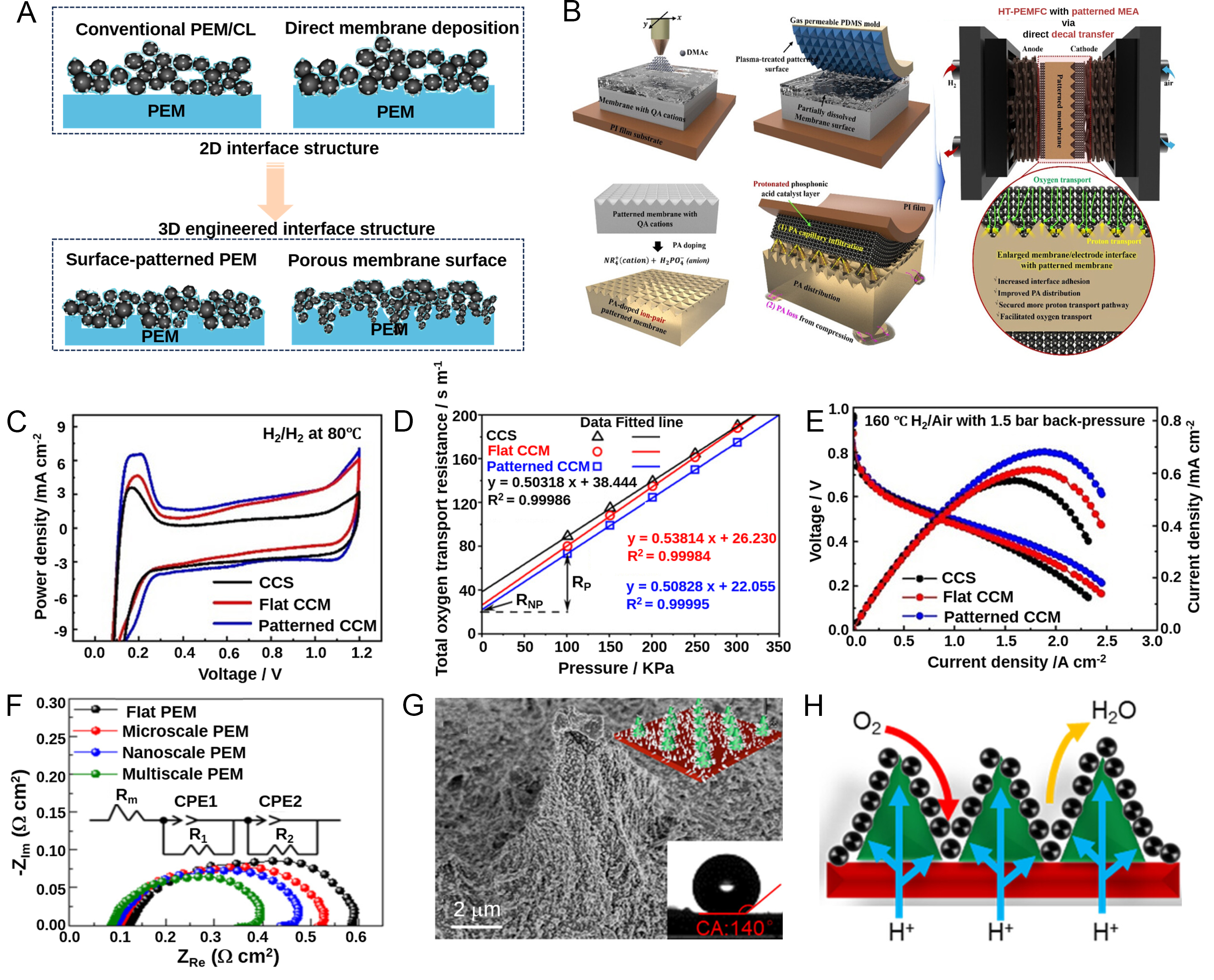
Figure 6. (A) Diagram showing the transformation from 2D flat contact interfaces to customized 3D interfacial structures; (B) Schematic diagram of the process and application of the inverted pyramid structure patterned film; (C) CV curves used for calculating the electrochemically active surface area; (D) Total oxygen-transport resistance for the flat CCM, the patterned CCM, and the CCS; (E) Polarization curves at 160 °C obtained by supplying dry H2/air with a back pressure of 1.5 bar. (B-E) Reprinted in part with permission from[158]. Copyright 2024, Wiley; (F) Nyquist plots derived from EIS tests of structured PEM-based MEAs under 0.6 V operation; the inset exhibits the corresponding equivalent circuit; (G) The SEM image of multiscale structure on PEM with insets presenting contact angle data; (H) Structural sketch of multiscale PEM coated with catalyst. (F-H) Reprinted in part with permission from[160]. Copyright 2023, American Chemical Society. PEM: Proton exchange membrane; QA: quaternary ammonium; DMAc: dimethylacetamide; PI: polyimide; PDMS: polydimethylsiloxane; HT-PEMFC: high-temperature proton exchange membrane fuel cell; MEA: membrane electrode assembly; PA: phosphoric acid; CCS: catalyst-coated substrate; CCM: catalyst-coated membrane; CA: contact angle; CV: cyclic voltammetry; EIS: electrochemical impedance spectroscopy; SEM: scanning electron microscopy.